Machine for the production of coiled gaskets
US20180085817A1
2018-03-29
15/711,081
2017-09-21
✅ Patent granted
US 10,207,311 B2
2019-02-19
-
-
Erica E Cadugan
2037-09-21
Abstract:
Machine (10) for the production of coiled gaskets from continuous strips, i.e. a master backing strip (1a) and sealing filler strip (1b), to be spirally wound onto rings, templates or inner rings (11), comprising at least: means (2) for feeding the strips (1a,1b) to be wound, a unit (100) for straightening and forming the backing strip (1a), a unit (200) for making incisions in and cutting the backing strip (1a), arranged downstream of the forming unit (100), a unit (300) for joining together the master strip (1a) and filler strip (1b) so as to form a combined strip (1) and cutting the filler strip (1b), a rotating spindle unit (400) for winding the combined strip (1), arranged downstream of the strip joining unit (300); a unit (500) for driving the ring or inner-ring (11) arranged downstream of the spindle (400), and a unit (600) for welding the master strip (1a), said units being designed to be able to produce automatically and in sequence a finished gasket, in accordance with a program managed by means (1000) for programming, controlling and actuating the operations.
Assignee:
- GSKET S.R.L. 1 🇮🇹 Crema (CR), Italy
Applicant:
Interested in similar patents?
Get notified when new applications in this technology area are published.
Classification:
B21D53/18 » CPC main
Making other particular articles rings, e.g. barrel hoops of hollow or C-shaped cross-section, e.g. for curtains, for eyelets
B65H81/06 » CPC further
Methods, apparatus, or devices for covering or wrapping cores by winding webs, tapes, or filamentary material, not otherwise provided for Covering or wrapping elongated cores
F16J15/12 IPC
Sealings between relatively-stationary surfaces with solid packing compressed between sealing surfaces with non-metallic packing with metal reinforcement or covering
B23P21/00 IPC
Machines for assembling a multiplicity of different parts to compose units, with or without preceding or subsequent working of such parts, e.g. with programme control
B23K26/0093 » CPC further
Working by laser beam, e.g. welding, cutting or boring combined with mechanical machining or metal-working covered by other subclasses than
F16J15/125 » CPC further
Sealings between relatively-stationary surfaces with solid packing compressed between sealing surfaces with non-metallic packing with metal reinforcement or covering with metal reinforcement generally perpendicular to the surfaces
B23K26/00 IPC
Working by laser beam, e.g. welding, cutting or boring
Y10T29/5145 » CPC further
Metal working; Plural diverse manufacturing apparatus including means for metal shaping or assembling; Separate tool stations for selective or successive operation on work including assembling or disassembling station and means to machine product to sever product to length
Y10T29/5197 » CPC further
Metal working; Plural diverse manufacturing apparatus including means for metal shaping or assembling Multiple stations working strip material
B21D53/16 IPC
Making other particular articles rings, e.g. barrel hoops
B23K26/21 IPC
Working by laser beam, e.g. welding, cutting or boring; Bonding by welding
B23P23/04 » CPC further
Machines or arrangements of machines for performing specified combinations of different metal-working operations not covered by a single other subclass for both machining and other metal-working operations
B65H81/02 IPC
Methods, apparatus, or devices for covering or wrapping cores by winding webs, tapes, or filamentary material, not otherwise provided for Covering or wrapping annular or like cores forming a closed or substantially closed figure
B23P15/00 » CPC further
Making specific metal objects by operations not covered by a single other subclass or a group in this subclass
B21D11/06 » CPC further
Bending not restricted to forms of material mentioned in only one of groups , , ; Bending not provided for in groups - ; Twisting Bending into helical or spiral form; Forming a succession of return bends, e.g. serpentine form
Description
The present invention relates to a machine for the production of coiled gaskets.
In the art numerous types of sealing gaskets produced in the form of rings and designed to perform static frontal sealing, for example of pipe connections, are known. It is also known that for the industrial production of these types of gaskets it is necessary to wind up in a spiral two strips which are superimposed on each other and have physical and mechanical characteristics which are very different from each other, in particular a first strip with a high mechanical strength, for example made of steel, which forms the backing for the second strip made of a material having high insulating and sealing characteristics, but a smaller mechanical strength.
Also known are machines which perform the construction of said gaskets either semi-manually, this requiring constant monitoring and auxiliary action on the part of an operator fully overseeing the machine, or semi-automatically, as illustrated in EP 0,707,906, this document describing an automatic machine for the production of gaskets obtained by spirally winding strips with different physical and mechanical characteristics onto a support ring, which machine comprises means for feeding said support rings to a spindle, means for feeding the strips to be wound to the support ring, a unit for applying radial pressure on said rings and a unit for welding one of said strips for starting winding and for closing the gasket once winding has been completed.
The known machine has in particular a tool-holder spindle which cannot be displaced along the plane perpendicular to the tool so as to adapt to the increase in diameter of the gasket during winding of the strip; on the contrary, the entire feeding unit must be manually displaced in order to adapt it to the different dimensions of the gaskets. Similar machines according to the preamble of claim 1 are described in CN 203 955 791 and KR 101 273 079.
Although performing their function, these known machines have, however, a number of drawbacks arising from the fact that they are unable to produce automatically, and without long machine downtime needed for retooling thereof, gaskets with diametral dimensions varying between a few tens of mm and four metres.
The technical problem which is posed therefore is that of providing a machine which provides a solution to the aforementioned problems of the prior art.
In connection with this problem it is also required that the machine should be able to use backing strips which are both pre-formed and flat and to produce gaskets wound onto disks, from which they are automatically separated and removed by the operator, or onto rings from which they are separated manually or onto inner rings of the said gasket to which the front end of the backing strip is welded and the gasket then wound.
These results are obtained according to the present invention by a machine for the production of coiled gaskets according to the characteristic features of claim 1.
Further details may be obtained from the following description of a non-limiting example of embodiment of the subject of the present invention, provided with reference to the accompanying drawings, in which:
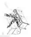
FIG. 1: shows a perspective view of an example of embodiment of the coiling machine according to the present invention;
FIG. 2: shows a top plan view of the machine according to FIG. 1 with the various operating units highlighted by broken-line circles;
FIG. 3: shows a perspective view of the unit for straightening and forming the backing strip;
FIG. 3a: shows a schematic vertically sectioned view of the forming disks;
FIG. 4: shows a perspective view of the unit for making incisions in and cutting the backing strip;
FIG. 4a: shows a vertically sectioned schematic view of the unit for making incisions in and cutting the backing strip;
FIG. 4b: shows a schematic view of the backing strip with incisions and cut;
FIG. 5: shows a top plan view of the unit for joining together the filler strip and backing strip with die for cutting the filler strip;
FIG. 6: shows a perspective view of the spindle unit with associated movement means;
FIG. 6a: shows a partially exploded perspective view of the spindle;
FIG. 6b: shows a view similar to that of FIG. 6a with winding disk mounted on the spindle;
FIG. 6c: shows a perspective view of the means for rotationally operating the spindle;
FIG. 7: shows a perspective view of the unit for driving the combined strip; and
FIG. 8: shows a schematic vertically sectioned view of the laser welding unit.
As shown a set of three reference axes will be assumed solely for easier description and without a limiting meaning, said axes having the following directions: a longitudinal direction X-X corresponding to the direction of extension and feeding of the strip inside the machine; a transverse direction Y-Y orthogonal to the longitudinal direction; a vertical direction Z-Z orthogonal to the other two directions, and a front part or upstream part corresponding to the side where the strip enters into the machine and a rear part or downstream part opposite to the front part. For the purposes of the present description the following are also defined:
-
- a backing strip 1a (FIG. 1) made of material with a high mechanical strength, such as steel, referred to below also for the sake of brevity as “master”;
- a sealing strip 1b (FIG. 1) made of material with high insulating and sealing characteristics, but with a smaller mechanical strength, also referred to below by the term “filler”;
- a strip 1 (FIG. 1) formed by joining together of the backing strip 1a and the sealing strip 1b;
- means external to the machine—not shown nor described in detail—for separately feeding the two strips, i.e. backing strip 1a and sealing strip 1b—to the coiling machine;
- means external to the machine, for programming, controlling and actuating the various working phases and moving parts of the machine, indicated only schematically by means of 1000 and not described in detail.
Based on the above definitions, the coiling machine according to the present invention described below comprises essentially (FIG. 1,2): a base 1 on which the following are mounted:
-
- a unit 100 for straightening and forming the backing strip 1a;
- a unit 200 for making incisions in and cutting the backing strip 1a;
- a unit 300 for joining together the strips, master 1a and filler 1b, with associated die for cutting the filler strip 1b;
- a spindle unit 400 for winding the combined strip 1;
- a unit 500 for driving the combined strip 1;
- a laser welding unit 600.
In greater detail and according to preferred embodiments:
The unit 100 for straightening and forming the backing strip comprises (FIG. 3):
-
- A plurality of vertical-axis pulleys 101 arranged parallel to the longitudinal direction X-X and suitably staggered relative to each other in the transverse direction Y-Y so as to be arranged alternately on opposite sides of the backing strip 1a for guiding and straightening it during its feeding movement inside the machine; the pulleys are mounted on respective support blocks 102 which are movable upon operation of means 103, for example of the screw type, for adjusting the relative position depending on the characteristics of the strip 1a.
- A pair 120 of forming disks comprising a first idle roller 121 and a second roller 122 motor-driven by means of an NC motor, said rollers being arranged on opposite sides of the strip 1a in the transverse direction Y-Y; the two disks have a respective relief 122a or recess 121a with complementary cross-section and dimensions, able to be clamped together on opposite sides of the strip so as to give it the desired form, for example a V-shaped or W-shaped form; the two disks are fixed to associated supports, one of which 123 is movable, said supports being designed to allow the adjustment of the relative interaxial distance depending on the characteristics of the steel strip 1a and provided with Belleville spring 123a for calibration.
An operating handle 125 which can be manually operated by the user is positioned on the top of the motor-driven disk 122.
Fixing of the disks 121,22 to the respective support is performed by means able to be mounted/removed so as to allow rapid changing thereof upon variation in the forming action required for the strip 1a.
According to the invention it is envisaged that the unit 100 for straightening and forming the master strip 1a also performs the following functions performed by means of a PLC-controlled brushless motor designed to generate a torque acting in both directions, i.e. clockwise or anti-clockwise direction of rotation:
-
- driving so as to feed the master strip after cutting and convey its front end to the winding spindle;
- adjusting the tension of the master when it is driven and wound by the spindle so as to ensure the compactness of the gasket, exerting a torque contrary to the movement of the spindle;
- measuring the length of the master 1a during winding and interruption of feeding when the pre-predefined design dimensions for production of the gaskets are achieved.
- The unit 200 for making incisions in and cutting the backing strip 1a, which is arranged downstream of the forming unit 100, comprises (FIG. 4) a first fixed half-die 210, formed by a guide and a matrix, and a second half-die 211, movable parallel to the transverse direction Y-Y, said half-dies being designed to make the notch 2a in the edge, the incision 2b and the cut 2c in the master 1a, as shown in FIG. 4b.
Inside the half-dies it is possible to identify the complementary male and female elements 210a and 211a which form the notch 2a in the edge of the strip, the complementary elements 210b and 211b which make the incision 2b in the strip and the elements 210c and 211c which perform the cut 2c in the strip. These operations are controlled and selected by means of respective pneumatic cylinders 211d,211e,211f performing a vertical movement along the direction Z-Z by means of sliding valve actuators arranged on the movable half-die.
-
- The unit 300 (FIG. 5) for joining together master 1a and filler 1b, arranged downstream of the unit 200 for performing incisions in and cutting the backing strip 1a, comprises a bearing 310 with axis parallel to the vertical axis Z-Z movable in the transverse direction Y-Y by conventional means so as to produce a thrusting force in the same transverse direction Y-Y suitable for ensuring joining together of the two strips, i.e. filler 1b and master 1a, which from that moment on proceed towards the following stations for working the filler 1b conveyed by the master 1a to which it adheres by means of friction;
the device 320 for cutting the filler strip 1b is positioned downstream of the bearing 310 and momentarily separates the filler from the master so as to perform the cut and then join the two together again; the device has a die 321 with a blade 322 mounted on a slide 323 which can be displaced along the direction Y-Y so as to allow cutting of only the filler strip 1b without damaging the backing strip 1a. - The spindle unit 400 (FIG. 6) for winding the strip 1 is arranged downstream of the strip joining unit 300 and comprises a cylindrical vertical-axis base 410 which is attached to a device 435 for imparting movement in the transverse direction Y-Y and which has fixed thereon the free end of the rod 436A of a pressure cylinder 436 which is also transverse thereto and the sleeve of which is positioned on a slide 435a which can be displaceably actuated by means of an NC controlled drive system and is designed to displace the axis of rotation of the spindle and therefore the centre of rotation upon variation in the size of the gasket during winding thereof.
- The unit 300 (FIG. 5) for joining together master 1a and filler 1b, arranged downstream of the unit 200 for performing incisions in and cutting the backing strip 1a, comprises a bearing 310 with axis parallel to the vertical axis Z-Z movable in the transverse direction Y-Y by conventional means so as to produce a thrusting force in the same transverse direction Y-Y suitable for ensuring joining together of the two strips, i.e. filler 1b and master 1a, which from that moment on proceed towards the following stations for working the filler 1b conveyed by the master 1a to which it adheres by means of friction;
The base 410 has, positioned thereon (FIG. 6a), a device 420 with self-centering radial jaws 421 which can be actuated by an underlying cylinder 421a and are designed to retain corresponding protrusions 431b of a shank 431 having, fixed thereon, a winding disk 431 which has a radial incision 431a for inserting one end of the strip 1 to be wound. The spindle is rotationally actuated by a gearmotor 421b.
The spindle unit also comprises a vertical-axis counter-thrust roller 435b (FIG. 6) situated opposite, in the direction Y-Y, to the winding disk 431 and movable by controlled operation means, from a rest position, separated from said disk, to a working position, close to the winding disk 431, so as to ensure relative tangential contact. During formation of the spirally wound band which constitutes the gasket being formed, the pressure cylinder 436 keeps the pressure exerted by means of suitable electro-pneumatic devices constant, thus causing the gradual retraction of the stem 436a, the position of which is monitored by a linear transducer 437.
This unit therefore performs the dual function of providing the winding torque necessary for forming the coiled gaskets up to a diameter of 500 mm using the disks of varying diameter.
As an alternative to and in the case of a gasket wound onto a template or inner ring the spindle unit is designed to provide an idly rotating pressure base for forming the gaskets with a diameter greater than 500 mm and up to 4 m by means of the rings which in this case are rotated by the drive unit 500.
-
- A drive unit 500 (FIG. 7) to be used for forming gaskets wound onto a template or an inner ring with diameter ranging from 500 mm to 4 m is arranged downstream of the spindle 440, fixed onto the device 435 for moving the said spindle and comprises a support 510 which has, fixed thereto, two transverse-axis rollers 520a,520b which are aligned with and above each other in the vertical direction Z-Z and moved rotatably by a gearmotor 530 via suitably sized gearwheels so as to engage with friction on the template or on the inner ring 11 and cause rotation thereof in the anti-clockwise direction. The bottom roller 520a is fixed, while the top roller 520b is movable and actuated by means of a pneumatic cylinder (not shown) which positions it on the inner edge of the ring or the inner ring, exerting a pressure sufficient to cause driving, by means of friction, of the winding ring or the inner ring. The unit has a fulcrum 540 on the support plate 435 of the spindle 400 so that, during use, the rotation of the drive unit 500 keeps the axis of the rollers for driving the templates or rings always radial relative to the gasket to be made so as to adapt to all the diameters ranging from 500 mm to 4 m.
- The welding unit 600 (FIG. 8) comprises, in a first example of embodiment, a laser device 610 which is conventional per se and the emission head 610a of which is arranged radially with respect to the gasket being forced so as to weld, with a variable number of welds as required, the master 1a onto itself after completion of the first turn and to the tail end of the master for closing the gasket. Laser welding is particularly preferred for gaskets which are intended for the nuclear energy sector where no contamination of the welding materials such as copper and like is permitted. This laser device is mounted on a support 611 which allows displacement of the unit from the parked position to the working position and rotation of the end part of the laser so as to keep a welding position always perfectly radial with respect to the gasket being formed, adapting automatically, by means of a suitable algorithm, to the variation in diameter, this being obtained owing to the particular position of the centre of rotation associated with the particular geometry of the device.
Alternatively it is envisaged using welding grippers which are per se conventional and therefore not described in detail and are suitable for all the other uses and have a cost less than that of the laser device.
With the configuration described above it is possible to produce coiled gaskets using three methods which depend on the different diameters required for the finished gasket:
-
- winding onto a disk fixed to the spindle, the gasket being detached from the disk once winding has been completed;
- winding onto an inner ring which, once winding has been completed, remains inside the gasket;
- winding onto a template, in turn consisting of a ring rotated by the drive unit arranged downstream of the spindle 400 on which the template usually rests.
In detail, the operating principle of the machine is as follows:
A) Winding onto a Disk
-
- the means for performing feeding of the two strips, i.e. backing strip or master 1a and sealing strip or filler 1b, are prepared;
- the winding disk 431 is selected depending on the size of the gasket to be produced and is attached to the spindle 400;
- the end of the backing strip 1a is inserted between the straightening rollers 101 and, by operation of the manually operated handle 125 of the forming roller 122, it is introduced into the fixed incision and cutting half-die 210 in order to prepare the front gasket end for insertion inside the notch 431a of the winding disk 431;
- the filler strip 1b is fed, conveying it as far as the entrance of the unit 300 for joining together the master 1a and filler 1b;
- the end of the backing strip is folded manually at right angles and inserted into the notch 431a of the winding disk 431;
- at this point the machine is ready to be started and the gasket automatically produced;
- after spirally winding the first two or three turns of the master 1a;
- welding thereof is performed;
- the filler 1b is fed and joined together with the master 1a forming the strip 1 which is driven by the drive unit, being spirally wound a predetermined number of turns defined for the gasket;
- a further two or more turns of the master 1a alone is performed in order to close the gasket fixed by further welding points;
- winding is continued until the programmed final diameter of the gasket is reached;
B) Winding onto an Inner Ring or Template - the means for performing feeding of the two strips, i.e. backing strip or master 1a and sealing or filler 1b, are prepared;
- the inner ring or winding template is selected depending on the gasket size to be produced;
- the inner ring or the template is positioned so that the respective circumferential edge rests on a roller of the spindle and on further rollers (not shown) so as to ensure the stability thereof both in the vertical direction and in the longitudinal and transverse directions;
- the driving unit 500 is positioned so that the associated rollers 520a,520b come into contact with a circumferential rim of the inner ring or template and cause rotation thereof;
- the strip joining, feeding and winding sequence described above is repeated;
- once winding has been completed the gasket with its inner ring incorporated is unloaded or the gasket is removed from the template which is ready for a new winding operation.
In all the winding situations the device 435 for moving the spindle unit 400 in the transverse direction Y-Y, during winding, translates so as to displace the axis of rotation of the spindle and therefore the centre of rotation upon variation in the size of the gasket to be produced.
In the case of winding onto an inner ring or template the driving unit 500, which is connected to the plate 435, modifies its position together with the spindle so as to keep constant the contact with the template or the inner ring by means of the rollers 520a,520b, and therefore the driving action, upon variation in the diameter of the gasket during winding.
It is therefore clear how with the machine according to the invention it is possible to obtain coiled gaskets both with a small diameter of between a few tens of mm and 500 mm, wound onto a disk fixed to the spindle, and with diameters greater than 500 mm and up to 4 m, formed on a winding ring (template) or inner ring.
After the first operation of feeding the master and filler strips to the machine, formation of the gaskets is performed by means of a completely automatic cycle which does not require or allow intervention of the operator during operation of the machine, eliminating in this way any risk of injury, this characterizing instead the manually operated machines.
In addition, the high degree of automation offers a greater reliability, repeatability and production speed with a consequent reduction in the downtime due to continuous retooling necessary for the machines of the known type when there is a variation in the diameters of the gaskets.
The machine according to the invention ensures moreover a better quality of formation of the welds obtained also owing to the guide means which ensure that the master 1a, the filler 1b and the combined strip 1 are always guided, thus preventing them from deviating in the transverse direction and ensuring a better planarity of the finished gasket, improving in this way the final characteristics thereof.
Although described in connection with a number of embodiments and a number of preferred examples of implementation of the invention, it is understood that the apparatus may be used also in sectors other than the gasket production sector and that the scope of protection of the present patent is determined solely by the claims below.
Claims
1. Machine (10) for the production of coiled gaskets from continuous strips, i.e. a master backing strip (1a) and a sealing filler strip (1b), to be spirally wound onto rings, templates or inner rings (11), comprising at least: means (2) for feeding the strips (1a, 1b) to be wound, a unit (100) for straightening and forming the backing strip (1a), a unit (200) for making incisions in and cutting the backing strip (1a), arranged downstream of the forming unit (100), a unit (300) for joining together the master strip (1a) and filler strip (1b) so as to form a combined strip (1) and cutting the filler strip (1b), a spindle unit (400) arranged downstream of the strip joining unit (300) and able to be rotationally operated by means of a gearmotor (421b) for winding the combined strip (1) until a predefined maximum diameter of the gasket is reached;
characterized in that it comprises
a device (435) for moving the spindle unit (400) in the transverse direction (Y-Y) and a unit (500) for rotationally driving the template or the inner-ring (11), which is arranged downstream of the spindle (400) and is mounted on the said device (435) for performing a movement in the transverse direction (Y-Y), so as to form gaskets with a diameter greater than the predefined maximum diameter, and a unit (600) for welding the master strip (1a), said units being designed to produce automatically and in sequence a finished gasket, in accordance with a program managed by means (1000) for programming, controlling and actuating the operations.
2. Machine according to claim 1, characterized in that said unit (100) for straightening and forming the backing strip (1a) comprises a plurality of vertical-axis pulleys (101) arranged parallel to the longitudinal direction (X-X) and staggered relative to each other in the transverse direction (Y-Y) so as to be arranged alternately on opposite sides of the backing strip (1a) and designed to guide and straighten it during its feeding movement inside the machine; a pair (120) of forming disks comprising a first idle roller (121) and a second roller (122) motor-driven by means of an NC motor and provided with a manual operating handle (125), said rollers being arranged on opposite sides of the strip (1a) in the transverse direction Y-Y; the two disks have a respective relief (122a) or recess (121a) with complementary cross-section and dimensions, able to be clamped together on either side of the strip so as to give it the desired form, the unit being designed to perform the driving movement for feeding the master strip after cutting so as to position its end in front of the winding spindle; exert a torque in the opposite direction to the movement of the spindle so as to adjust the tension of the master strip during winding; and measure the length of the master strip (1a) during winding.
3. Machine according to claim 2, characterized in that the pulleys (101) are mounted on respective support blocks (102) movable upon operation of means (103) and the two disks are fixed to associated supports, one (123) of which is movable.
4. Machine according to claim 1, characterized in that said unit (200) for making incisions in and cutting the backing strip (1a) comprises a first fixed half-die (210) and a second half-die (211) movable parallel to the transverse direction (Y-Y), said half-dies being respectively provided with complementary male and female elements (210a,211a) designed to form the notch (2a) on the edge, elements (210b,211b) which make the incision (2b) in the strip and elements (210c,211c) which perform cutting (2c) of the master strip (1a).
5. Machine according to claim 1, characterized in that said unit (300) for joining together master strip (1a) and filler strip (1b) and for cutting the backing strip (1a), which is arranged downstream of the incision unit (200), comprises a bearing (310) with its axis parallel to the vertical axis (Z-Z), movable in the transverse direction (Y-Y) and able to generate a thrusting force in the same transverse direction (Y-Y) so as to perform joining together of the two strips, i.e. filler strip (1b) and master strip (1a), forming the combined strip (1), and a die (321) with a blade (322) mounted on a slide (323) able to be displaced along the direction (Y-Y) so as to allow cutting of the filler strip (1b) alone.
6. Machine according to claim 1, characterized in that said rotating spindle unit (400) for winding the combined strip (1) comprises a cylindrical vertical-axis base (410) which is fastened to said device (435) for imparting movement in the transverse direction (Y-Y), having, fixed thereon, the free end of the rod (436a) of a cylinder (436) which is also transverse and the sleeve of which is positioned on a slide (435a) which can be displaceably actuated by means of an N.C. controlled drive system and is designed to displace the axis of rotation of the spindle and therefore the centre of rotation upon variation in the size of the gasket during winding thereof.
7. Machine according to claim 2, characterized in that the base (410) has, positioned thereon, a device (420) with self-centering radial jaws (421) which can be actuated by an underlying cylinder (421a) and are designed to retain corresponding protrusions (431b) of a support shank (431c) of a winding disk (431) which has a radial incision (431a) for inserting one end of the strip (1) to be wound.
8. Machine according to claim 2, characterized in that the spindle unit comprises a vertical-axis counter-thrust roller (435b) situated opposite, in the direction (Y-Y), to the winding disk (431) and movable, from a rest position, removed from said disk, to a working position, close to the winding disk (431), so as to ensure relative tangential contact.
9. Machine according to claim 1, characterized in that said unit (500) for driving the strip (1) is fixed on the spindle movement device (435) and comprises a support block (510) to which two horizontal-axis rollers (520), i.e. a stationary bottom roller (520a) and a movable upper roller (520b), are fixed, said rollers being aligned one on top of the other one in the vertical direction (Z-Z) and being rotationally moved by a gearmotor (530) so as to engage with friction on the ring or the inner ring and cause rotation thereof in an anti-clockwise direction.
10. Machine according to claim 1, characterized in that said driving unit (500) has a fulcrum (540) for rotation relative to the support plate (435) of the spindle (400), designed to allow rotation of said unit with respect to the plate and to maintain the relative radial orientation of the axis of the rollers driving the templates or inner ring (11) and the gasket when there is a variation in the dimensions of the latter.
11. Machine according to claim 1, characterized in that said welding unit (600) comprises a laser device (610), the emission head (610a) of which is arranged radially with respect to the gasket being formed.
12. Machine according to claim 11, characterized in that said laser device (610) is mounted on a support (611) designed to displace the unit from a parked position into a working position and cause rotation of the end part of the laser so as to maintain a welding position which is always radial with respect to the gasket being formed.
13. Machine according to claim 12, characterized in that said rotation of the laser is controlled by the programming, control and actuating means (1000) so as to adapt the position to the variation in diameter of the gasket being formed.
Images & Drawings included:


Sources:
- United States Patent and Trademark Office - verify current appl. status at the USPTO↗
Recent applications in this class:
- » 20090056223 2009-03-05
QUENCH RING RIM AND METHODS FOR FABRICATING - » 20080053179 2008-03-06
CLAMPING SLEEVE AND APPARATUS FOR FORMING THE SAME