Assembly of bicycle frame, fork, and handlebar stem
US20180093735A1
2018-04-05
15/283,298
2016-10-01
✅ Patent granted
US 10,513,305 B2
2019-12-24
-
-
Joseph M Rocca | Marlon A Arce
Palomar Patent | Calif Tervo
2036-10-01
Abstract:
The present invention is an assembly of bicycle frame, fork, and handlebar stem that improves the safety and performance of bicycle riding by placing a mechanical bearing above the handlebar stem which reduces the torsional stress on the fork steering column.
Assignee:
- Veselin Mandaric 1 🇺🇸 San Marcos, CA, United States
Applicant:
Interested in similar patents?
Get notified when new applications in this technology area are published.
Classification:
B62K21/02 » CPC further
Steering devices Front wheel forks or equivalent, e.g. single tine
B62K3/02 » CPC further
Bicycles Frames
B62K21/18 » CPC further
Steering devices Connections between forks and handlebars or handlebar stems
B62K19/32 » CPC main
Cycle frames; Frame parts shaped to receive other cycle parts or accessories Steering heads
Description
BACKGROUND OF THE INVENTION
The present invention is directed towards a bicycle that provides a high-quality riding experience. The assembly of bicycle frame, fork, and handlebar stem is an area that can still be improved in order to provide the user a better and safer ride.
BRIEF SUMMARY OF THE INVENTION
The present invention is an assembly of bicycle frame, fork, and handlebar stem that improves the safety and performance of bicycle riding by placing a mechanical bearing above the handlebar stem which reduces the torsional stress on the fork steering column.
BRIEF DESCRIPTION OF THE DRAWING
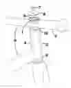
The drawing is a depiction of the assembly of bicycle frame, fork, and handlebar stem from a three-dimensional perspective, with broken lines representing internal elements.
DETAILED DESCRIPTION OF THE INVENTION
In traditional bicycle manufacturing, the handlebar stem is positioned above the top of the head tube. Furthermore, the fork steering column is inserted through the head tube and through one mechanical bearing at the bottom of the head tube and one mechanical bearing at the top of the head tube. Then the handlebar stem is slid over the protruding part of the fork steering column, and secured.
Having the handlebar stem above the upper mechanical bearing creates a high amount of torsional stress on the fork steering column, between the handlebar stem and the upper mechanical bearing. This sometimes leads to fork steering column failure and even complete separation of the handlebar from the fork steering column, resulting in a loss of control over the bicycle and an unavoidable crash.
In the present invention, these issues are addressed by strengthening the region where the head tube, handlebar stem, and fork steering column meet.
Referring to the drawing, the handlebar stem 2 is inserted through the front of the head tube 3 of the bicycle frame 6, and a mechanical bearing 1 is placed directly above the handlebar stem 2. The fork steering column 4 is inserted through the bottom of the head tube 3. The fork steering column 4 also passes through a mechanical bearing 9 at the bottom of the head tube 3 and a mechanical bearing 10 directly below the handlebar stem 2, the usual positions for mechanical bearings in a conventional bicycle headset design. The handlebar stem 2 is secured and compressed by a central bolt 7 inserted through a cap 8. Because of this arrangement, the fork steering column 4 is under much less torsional stress. The handlebar stem 2 is aligned with the front wheel of the bicycle by way of the non-circular cross-sectional shape 5 of the fork steering column 4 and matching vertical hole inside the handlebar stem 2 within the head tube 3.
Claims
What is claimed is:1. An assembly of bicycle frame, fork, and handlebar stem, where there is a mechanical bearing positioned above, in, or about the upper portion of the handlebar stem, in the same axis as the head tube and the fork steering column.
2. An assembly of bicycle frame, fork, and handlebar stem, which comprises:
(a) a fork with a steering column of non-circular cross sectional shape
(b) a handlebar stem with hole that matches the cross sectional shape of the fork steering column, so that the fork steering column fits snugly through this hole and the shape prevents the handlebar stem from spinning around the fork steering column
Images & Drawings included:

Sources:
- United States Patent and Trademark Office - verify current appl. status at the USPTO↗
Recent applications in this class:
- » 20250136234 2025-05-01
BICYCLE COMPRESSION RING ASSEMBLY AND METHOD FOR INSTALLING SAID ASSEMBLY - » 20250091686 2025-03-20
DRIVE MODULE FOR BICYCLE, CARGO MODULE FOR BICYCLE, AND CARGO BICYCLE - » 20250019028 2025-01-16
HEAD TUBE ASSEMBLY - » 20240002009 2024-01-04
Bicycle Rotation Limiting Structure - » 20220402571 2022-12-22
Head Tube Assembly - » 20220402570 2022-12-22
HEADSET WITH DAMPING BEARING ASSEMBLY - » 20220234674 2022-07-28
Frame and mobility scooter - » 20210214036 2021-07-15
Bicycle handlebar assembly with v-shaped stem - » 20210129935 2021-05-06
Cable routing system of bicycle and stem thereof - » 20210078665 2021-03-18
Suspension assembly and bicycle having a suspension assembly