Energy transfer system (ETS)
US20180135873A1
2018-05-17
15/530,198
2016-12-13
✅ Patent granted
US 10,077,913 B2
2018-09-18
-
-
Justin Jonaitis
Michael D. Eisenberg
2036-12-13
Abstract:
Transfer of heat energy from within a building to the outside air by means of fans, heat pipes and circulating water in a closed loop system.
Applicant:
Interested in similar patents?
Get notified when new applications in this technology area are published.
Classification:
F24F11/00 IPC
Control or safety arrangements
F24F5/0003 » CPC main
Air-conditioning systems or apparatus not covered by or , e.g. using solar heat or combined with household units such as an oven or water heater Exclusively-fluid systems
F24F1/0007 » CPC further
Room units for air-conditioning, e.g. separate or self-contained units or units receiving primary air from a central station Indoor units, e.g. fan coil units
F24F11/30 » CPC further
Control or safety arrangements for purposes related to the operation of the system, e.g. for safety or monitoring
F24F11/83 » CPC further
Control or safety arrangements; Control systems characterised by their outputs; Constructional details thereof for controlling the temperature of the supplied air by controlling the supply of heat-exchange fluids to heat-exchangers
F24F11/85 » CPC further
Control or safety arrangements; Control systems characterised by their outputs; Constructional details thereof for controlling the temperature of the supplied air by controlling the supply of heat-exchange fluids to heat-exchangers using variable-flow pumps
F24F2110/10 » CPC further
Control inputs relating to air properties Temperature
F28D15/00 IPC
Heat-exchange apparatus with the intermediate heat-transfer medium in closed tubes passing into or through the conduit walls ; Heat-exchange apparatus employing intermediate heat-transfer medium or bodies
F28D15/00 IPC
Heat-exchange apparatus employing intermediate heat-transfer media or bodies
F24F5/00 IPC
Air-conditioning systems or apparatus not covered by or , e.g. using solar heat or combined with household units such as an oven or water heater
F24F1/00 IPC
Room units for air-conditioning, e.g. separate or self-contained units or units receiving primary air from a central station
Description
TECHNICAL FIELD AND INDUSTRIAL APPLICABILITY OF THE INVENTION
This invention relates to the removal of heat from a room in a building by means of mechanical fans. This present invention uses mechanical fans heat tubes and circulating water in a closed loop system to remove heat from the room and dump to atmosphere; instead of mechanical fans, refrigerant and a compressor in a variable refrigerant volume (VRV) system, or mechanical fans and chilled water.
BACKGROUND TO THE INVENTION
During the summer, rooms in buildings get very hot and a means of cooling these rooms is required to make them more comfortable to be in. Currently fans with a cooling coil using refrigerant (VRV) are used or fans with a cooling coil using chilled water are used. In both cases the heat is removed from the room and dumped into the atmosphere using more fans.
DESCRIPTION OF THE INVENTION
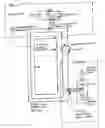
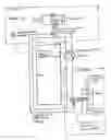
A rectangular box with a fan inside draws hot air from a room and passes it over a set of heat pipes which have one end in the hot air stream and one end in a sealed circulating pipe of cold water. The heat pipes remove heat from the hot air stream and transfer it to the cold water which is then heated up. The cold water which is now hot is pumped to an outside box where another set of heat pipes with one end in the sealed circulating pipe of now hot water remove heat from the hot water and transfer it to air, with a fan drawing the air across the hot heat pipes and blowing the hot air out to atmosphere. The hot water now has all of the heat removed and becomes cold water which is circulated back to the inside box where the cycle is repeated. From the inside box to the outside box the sealed circulating pipe is hot, from the outside box to the inside box the same sealed circulating pipe is cold. A room temperature sensor linked to the pump controls, enables the pump to switch off (no heat removed) once the room is at a set temperature and switch on (heat removed) when the room is above set temperature. The variable speed pump speeds up or slows down the flow of water circulating in the pipe depending on how much heat needs to be removed.
DESCRIPTION OF DRAWING 1-1
Drawing 1-1 shows the typical arrangement as described in section (03) above
Claims
1. What is claimed is the principal of using heat pipes, fans and a sealed circulating pipe of water to transfer heat energy from within a building to the outside/external air.
Images & Drawings included:
Sources:
- United States Patent and Trademark Office - verify current appl. status at the USPTO↗
Recent applications in this class:
- » 20240263811 2024-08-08
WATER TANK MODULE FOR AIR-CONDITIONING WATER SYSTEM AND AIR-CONDITIONING WATER SYSTEM - » 20240044529 2024-02-08
COOLING DISTRIBUTION UNIT AND ASSEMBLING/DISASSEMBLING METHOD THEREOF - » 20230228430 2023-07-20
Valve system and methods - » 20230184446 2023-06-15
System and method for comprehensive utilization of renewable energy and waste heat of data center - » 20230033068 2023-02-02
Single primary loop, dual secondary loop hydronic HVAC system and methods of operation - » 20220146126 2022-05-12
Heat pump assembly and controlling of the same - » 20220049864 2022-02-17
Single primary loop, dual secondary loop hydronic HVAC system and methods of operation - » 20210231319 2021-07-29
Combined heating and cooling system - » 20190242597 2019-08-08
Air conditioner system, air conditioner control device, air conditioner method, and program for control using water circulation and based on indoor latent and sensible heat loads - » 20180266711 2018-09-20
Piping stick systems and methods