RFID transponder
US20180151942A1
2018-05-31
15/818,166
2017-11-20
✅ Patent granted
US 11,005,152 B2
2021-05-11
-
-
Ab Salam Alkassim, Jr.
Jeffrey T. Placker, Esq | Holland & Knight LLP
2037-11-20
Abstract:
An RFID transponder, comprising an antenna, comprising a radiating element an IC, and a ground plane arranged under the radiating element, the ground plane being solid without openings. The radiating element comprises a near field communication section extending over the edge of the ground plane for enabling near field communication of the antenna by the ground plane from backside of the RFID transponder.
Assignee:
- Confidex Oy 12 🇫🇮 Tampere, Finland
Applicant:
Interested in similar patents?
Get notified when new applications in this technology area are published.
Classification:
H01Q1/2225 » CPC main
Details of, or arrangements associated with, antennas; Supports; Mounting means by structural association with other equipment or articles associated with components used in interrogation type services, i.e. in systems for information exchange between an interrogator/reader and a tag/transponder, e.g. in Radio Frequency Identification [RFID] systems used in active tags, i.e. provided with its own power source or in passive tags, i.e. deriving power from RF signal
G06K19/0723 » CPC further
Record carriers for use with machines and with at least a part designed to carry digital markings characterised by the kind of the digital marking, e.g. shape, nature, code; Record carriers with conductive marks, printed circuits or semiconductor circuit elements, e.g. credit or identity cards also with resonating or responding marks without active components with integrated circuit chips the record carrier comprising an arrangement for non-contact communication, e.g. wireless communication circuits on transponder cards, non-contact smart cards or RFIDs
H01Q7/00 » CPC further
Loop antennas with a substantially uniform current distribution around the loop and having a directional radiation pattern in a plane perpendicular to the plane of the loop
H01Q9/0421 » CPC further
Electrically-short antennas having dimensions not more than twice the operating wavelength and consisting of conductive active radiating elements; Resonant antennas; Substantially flat resonant element parallel to ground plane, e.g. patch antenna with a shorting wall or a shorting pin at one end of the element
H01Q1/22 IPC
Details of, or arrangements associated with, antennas; Supports; Mounting means by structural association with other equipment or articles
G06K19/07 IPC
Record carriers for use with machines and with at least a part designed to carry digital markings characterised by the kind of the digital marking, e.g. shape, nature, code; Record carriers with conductive marks, printed circuits or semiconductor circuit elements, e.g. credit or identity cards also with resonating or responding marks without active components with integrated circuit chips
H01Q1/48 » CPC further
Details of, or arrangements associated with, antennas Earthing means; Earth screens; Counterpoises
H01Q9/04 IPC
Electrically-short antennas having dimensions not more than twice the operating wavelength and consisting of conductive active radiating elements Resonant antennas
G06K19/077 IPC
Record carriers for use with machines and with at least a part designed to carry digital markings characterised by the kind of the digital marking, e.g. shape, nature, code; Record carriers with conductive marks, printed circuits or semiconductor circuit elements, e.g. credit or identity cards also with resonating or responding marks without active components with integrated circuit chips Constructional details, e.g. mounting of circuits in the carrier
G06K19/07722 » CPC further
Record carriers for use with machines and with at least a part designed to carry digital markings characterised by the kind of the digital marking, e.g. shape, nature, code; Record carriers with conductive marks, printed circuits or semiconductor circuit elements, e.g. credit or identity cards also with resonating or responding marks without active components with integrated circuit chips; Constructional details, e.g. mounting of circuits in the carrier; Physical layout of the record carrier the record carrier being multilayered, e.g. laminated sheets
G06K19/07773 » CPC further
Record carriers for use with machines and with at least a part designed to carry digital markings characterised by the kind of the digital marking, e.g. shape, nature, code; Record carriers with conductive marks, printed circuits or semiconductor circuit elements, e.g. credit or identity cards also with resonating or responding marks without active components with integrated circuit chips; Constructional details, e.g. mounting of circuits in the carrier the record carrier being capable of non-contact communication, e.g. constructional details of the antenna of a non-contact smart card Antenna details
H01Q1/2208 » CPC further
Details of, or arrangements associated with, antennas; Supports; Mounting means by structural association with other equipment or articles associated with components used in interrogation type services, i.e. in systems for information exchange between an interrogator/reader and a tag/transponder, e.g. in Radio Frequency Identification [RFID] systems
G06K1/20 » CPC further
Methods or arrangements for marking the record carrier in digital fashion Simultaneous marking of record carrier and printing-out of data, e.g. printing-punch
Description
RELATED APPLICATIONS
The subject application claims the benefit of European Patent Application No. 16200609.2, filed on Nov. 25, 2016. The content of which is herein incorporated by reference in its entirety.
BACKGROUND
The invention relates to an RFID transponder.
It is known to code RFID transponders by using RFID printer-encoders. An RFID printer-encoder typically prints visual information like barcode or human readable on top of the RFID transponder. Same or, alternatively, different information is electronically programmed inside the IC memory of the RFID transponder by the reader antenna of the printer.
However, some RFID transponders have structures which may isolate the antenna of the transponder from the radiation of the reader antenna of the printer. Said structure of the RFID transponder is usually the ground plane of the antenna of said transponder. For instance, if the printer has its reader antenna below the ground plane, it is usually not possible to couple the reader antenna to the antenna of the RFID transponder. Therefore the RFID transponder cannot be encoded in said printer.
BRIEF DESCRIPTION
Viewed from a first aspect, there can be provided an RFID transponder, comprising an antenna, comprising a radiating element, an IC, a ground plane arranged under the radiating element, the ground plane being solid without openings, the radiating element comprising a near field communication section extending over the edge of the ground plane for enabling near field communication of the antenna by the ground plane from backside of the RFID transponder.
Thereby an RFID transponder which may be encoded in most RFID printers may be achieved. The near field communication section enables near field communication by and beyond the ground plane. Down to this, there is no need, for instance, for a separate secondary antenna, which would be adapted for near field communication with e.g. a RFID printer-encoder or a RFID encoder.
The RFID transponder is characterised by what is stated in the characterising part of the independent claim. Some other embodiments are characterised by what is stated in the other claims. Inventive embodiments are also disclosed in the specification and drawings of this patent application. The inventive content of the patent application may also be defined in other ways than defined in the following claims. The inventive content may also be formed of several separate inventions, especially if the invention is examined in the light of expressed or implicit sub-tasks or in view of obtained benefits or benefit groups. Some of the definitions contained in the following claims may then be unnecessary in view of the separate inventive ideas. Features of the different embodiments of the invention may, within the scope of the basic inventive idea, be applied to other embodiments.
In one embodiment, a spacer layer made of a dielectric material is arranged between the antenna element and the ground plane.
In one embodiment, the antenna comprises two radiating elements arranged at a distance from each other, and the IC being situated between said two radiating elements.
In one embodiment, the radiating element is quadrangle.
In one embodiment, the near field communication section is provided by prolongation of two parallel sides of the quadrangle, the near field communication section thus being situated at one edge of the radiating element.
In one embodiment, the radiating element is a meandering element.
In one embodiment, the radiating element is a PIFA element.
In one embodiment, the radiating element is a loop element.
In one embodiment, the near field communication section is provided on at least two edges of the radiating element by extending said edges over the edge of the ground plane.
In one embodiment, the antenna comprises at least two radiating elements, and only one of said radiating elements comprises the near field communication section.
In one embodiment, the near field communication section is provided by a projection extending from the radiating element and having an elongated aspect ratio.
In one embodiment, the projection comprises at least one bend.
BRIEF DESCRIPTION OF FIGURES
Some embodiments illustrating the present disclosure are described in more detail in the attached drawings, in which
FIG. 1 is a schematic top view of an RFID transponder,
FIG. 2 is a schematic top view of another RFID transponder,
FIG. 3 is a schematic top view of a third RFID transponder, and
FIG. 4 is a schematic top view of a fourth RFID transponder.
In the figures, some embodiments are shown simplified for the sake of clarity. Similar parts are marked with the same reference numbers in the figures.
DETAILED DESCRIPTION
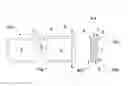
FIG. 1 is a schematic top view of an RFID transponder. The RFID transponder 100 may comprise a printable surface or face element 1, an antenna element 2, and an IC 3. The RFID transponder 100 further comprises a ground plane 4 that is made of metal or some other electrically conductive material or composition. The ground plane 4 is solid without openings and arranged under the antenna element 2.
Layers of the RFID transponder 100 are typically attached together with suitable adhesive layers and sealed by e.g. a silicone liner.
The RFID transponder 100 may further comprise a spacer layer 7 that is arranged to make distance between the antenna element 2 and the ground plane 4. The spacer layer 7 is made of a dielectric material, such as polyethylene PE, polypropylene PP polyethylene terephthalate PET, in a solid or a foamed form.
The printable surface 1 is arranged on the top side of the transponder 100. The surface 1 may be a thin material layer manufactured from e.g. paper or plastic based material, or a layer of paint(s) and/or lacquer(s).
The antenna element 2 and the IC 3 (together with further electronic components, if any) may be arranged to a structural module such as an inlay 5 comprising a dielectric substrate.
The edges or peripheral shape of the ground plane 4 is shown by dash line in Figures. The radiating element 2 comprises a near field communication section 6 that extends over the edge of the ground plane 4 for enabling near field communication of the antenna by the ground plane 4 from backside of the RFID transponder 100.
In the embodiment shown in FIG. 1, the antenna comprises two radiating elements 2 the shape of which is quadrangle and which are arranged at a distance from each other. The IC 3 is situated between the radiating elements 2. The near field communication section 6 is provided by prolongation of two parallel sides of one of the quadrangles, so the near field communication section 6 is situated at one edge of the radiating element 2.
For example, if the reader antenna of an RFID printer-encoder, such as Zebra RZ600, is on the bottom side BOT of the RFID transponder 100, the near field communication section 6 makes it possible to couple said reader antenna with the antenna element 2 of the transponder although the reader antenna is situated opposite side of the ground plane 4 compared to the antenna element 2 of the transponder, thus enabling encoding the RFID transponder 100.
The radiating element 2 as such may be of any type of radiating element suitable for the RFID transponder 100. Some further examples of the radiating element are a meandering element, a PIFA element and a loop element.
Also the shape of the radiating element 2 as well as number of the radiating elements 2 may vary. For instance, the number of the radiating elements 2 may be one, two, three, four or even more.
Furthermore, the coupling of the IC 3 and the radiating element 2 may vary: a galvanic, an inductive or capacitive coupling may be used.
FIG. 2 is a schematic top view of another RFID transponder. According to an aspect, the near field communication section 6 is provided on at least two edges of the radiating element 2 by extending said edges over the edge of the ground plane 4. In the embodiment shown in FIG. 2, all the edges of the radiating elements 2 extends over the ground plane 4—except the edge being towards the IC 3. An advantage is that the RFID transponder 100 can be encoded in various types of encoders having diverse antenna configurations.
It is to be noted that the IC 3 may also be arranged on/in the near field communication section 6.
FIG. 3 is a schematic top view of a third RFID transponder. In this embodiment, only one of plurality of radiating elements 2 comprises the near field communication section 6. This embodiment is quite similar to that shown in FIG. 1, except the near field communication section 6 being arranged at the end edge of the radiating element 2. An advantage is that the production of the RFID transponder may be implemented in simple and effective way.
FIG. 4 is a schematic top view of a fourth RFID transponder. According to an aspect, the near field communication section 6 is provided by a projection extending from the radiating element 2 and having an elongated aspect ratio. In the embodiment shown in FIG. 4, the projection comprises one bend. The projection may also be straight, meandering, curved etc. An advantage is that the near field communication section 6 may be designed so that its influence on the main antenna or the radiating element(s) is negligible.
The invention is not limited solely to the embodiments described above, but instead many variations are possible within the scope of the inventive concept defined by the claims below. Within the scope of the inventive concept the attributes of different embodiments and applications can be used in conjunction with or replace the attributes of another embodiment or application.
The drawings and the related description are only intended to illustrate the idea of the invention. The invention may vary in detail within the scope of the inventive idea defined in the following claims.
REFERENCE SYMBOLS
-
- 1 printable coating
- 2 an antenna element
- 3 IC
- 4 ground plane
- 5 inlay
- 6 near field communication section
- 7 spacer layer
- 100 RFID transponder
- BOT bottom side
- TOP top side
Claims
1. An RFID transponder, comprising
an antenna, comprising a radiating element,
an IC,
a ground plane arranged under the radiating element,
the ground plane being solid without openings,
the radiating element comprising a near field communication section extending over the edge of the ground plane for enabling near field communication of the antenna by the ground plane from backside of the RFID transponder.
2. The RFID transponder as claimed in claim 1, wherein a spacer layer made of a dielectric material is arranged between the antenna element and the ground plane.
3. The RFID transponder as claimed in claim 1, wherein the antenna comprises two radiating elements arranged at a distance from each other, and
the IC being situated between said two radiating elements.
4. The RFID transponder as claimed in claim 1, wherein the radiating element is quadrangle.
5. The RFID transponder as claimed in claim 4, wherein the near field communication section is provided by prolongation of two parallel sides of the quadrangle, the near field communication section thus being situated at one edge of the radiating element.
6. The RFID transponder as claimed in claim 1, wherein the radiating element is a meandering element.
7. The RFID transponder as claimed in claim 1, wherein the radiating element is a PIFA element.
8. The RFID transponder as claimed in claim 1, wherein the radiating element is a loop element.
9. The RFID transponder as claimed in claim 1, wherein the near field communication section is provided on at least two edges of the radiating element by extending said edges over the edge of the ground plane.
10. The RFID transponder as claimed in claim 5, wherein the antenna comprises at least two radiating elements, and
only one of said radiating elements comprises the near field communication section.
11. The RFID transponder as claimed in claim 6, wherein the antenna comprises at least two radiating elements, and
only one of said radiating elements comprises the near field communication section.
12. The RFID transponder as claimed in claim 1, wherein the near field communication section is provided by a projection extending from the radiating element and having an elongated aspect ratio.
13. The RFID transponder as claimed in claim 12, wherein the projection comprises at least one bend.
Images & Drawings included:


Sources:
- United States Patent and Trademark Office - verify current appl. status at the USPTO↗
Similar patent applications:
- » 20180129924
RFID transponder, RFID transponder arrangement and method for communication between an RFID transponder and a reading device - » 20090212953
RFID-transponder and device having an RFID-transponder as well as a method of making an antenna for an RFID-transponder - » 20120061475
Method for Providing Inductively Coupled Radio Frequency Identification (RFID) Transponder, and RFID Transponder - » 20100007567
ANTENNA FOR AN RFID TRANSPONDER AND RFID TRANSPONDER - » 20070057771
RFID transponder and RFID transponder chip - » 20170316299
RFID transponder and RFID transponder web - » 20110266351
Method for producing an RFID transponder product, and RFID transponder product produced using the method - » 20180039802
RFID Apparatus for Communicating with RFID Transponders and Method of Associating RFID Transponders - » 20210133526
RFID transponder and method of operating an RFID transponder - » 20210342661
RFID transponder and method of operating an RFID transponder
Recent applications in this class:
- » 20250167425 2025-05-22
SURGICAL SPONGES WITH FLEXIBLE RFID TAGS - » 20250141087 2025-05-01
ANTENNA INLAY FOR A DOCUMENT AND DOCUMENT WITH SUCH AN ANTENNA INLAY - » 20250038395 2025-01-30
RFID Antenna - » 20240235005 2024-07-11
SURGICAL SPONGES WITH FLEXIBLE RFID TAGS - » 20240136700 2024-04-25
Surgical sponges with flexible RFID tags - » 20240097310 2024-03-21
WIRELESS SENSOR WITH EXTENDED POWER FOR USE WITH SPACECRAFT - » 20240039140 2024-02-01
Modular Antenna for an RFID Reading Device - » 20240014542 2024-01-11
WIRELESS PASSIVE ELECTRONIC COMPONENT AND ASSOCIATED READING SYSTEM - » 20230395966 2023-12-07
RFID TAG AND MANUFACTURING METHOD THEREOF - » 20230335881 2023-10-19
MOUNTING MEMBER WITH RFID TAG, MANUFACTURING METHOD FOR MOUNTING MEMBER WITH RFID TAG, HEAD UNIT OF MOUNTING MEMBER WITH RFID TAG, AND RFID TAG MOUNT UNIT
Recent applications for this Assignee:
- » 20210049437 2021-02-18
RFID label and use - » 20180150737 2018-05-31
RFID transponder web - » 20180025673 2018-01-25
Safety lock - » 20170316299 2017-11-02
RFID transponder and RFID transponder web - » 20170297850 2017-10-19
Method for arranging a material web on a core - » 20110248833 2011-10-13
RFID SYSTEM - » 20110148582 2011-06-23
RFID TRANSPONDER AND METHOD - » 20110017832 2011-01-27
RFID tag - » 20100213264 2010-08-26
METHOD FOR RFID TAGGING - » 20100065647 2010-03-18
Radio frequency identification tag