Engineering high-performance palladium core magnesium oxide porous shell nanocatalysts via heterogeneous gas-phase synthesis
US20180193820A1
2018-07-12
15/736,721
2016-06-28
✅ Patent granted
US 10,828,622 B2
2020-11-10
WO; PCT/JP2016/003093; 20160628
WO; WO2017/002357; 20170105
Haytham Soliman
Westerman, Hattori, Daniels & Adrian, LLP
2036-06-28
Abstract:
A novel catalyst includes a plurality of nanoparticles, each nanoparticle including a core made of a catalytic metal and a porous shell surrounding the core, made of metal oxide, the porous shell preserving a catalytic function of the core and reducing reduction of the core and coalescence of the nanoparticles.
Inventors:
- Cathal Cassidy 10 🇯🇵 Okinawa, Japan
- Mukhles Ibrahim SOWWAN 7 🇯🇵 Okinawa, Japan
- Vidya Dhar SINGH 4 🇯🇵 Okinawa, Japan
Assignee:
- OKINAWA INSTITUTE OF SCIENCE AND TECHNOLOGY SCHOOL CORPORATION 56 🇯🇵 Okinawa, Japan
Applicant:
Interested in similar patents?
Get notified when new applications in this technology area are published.
Classification:
B01J35/0006 » CPC further
Catalysts, in general, characterised by their form or physical properties Catalysts containing parts with different compositions
B01J35/0013 » CPC further
Catalysts, in general, characterised by their form or physical properties Colloids
B01J35/0086 » CPC further
Catalysts, in general, characterised by their form or physical properties; Catalysts characterised by their physical properties; Distribution of the active metal ingredient egg-yolk like
B01J37/0072 » CPC further
Processes, in general, for preparing catalysts; Processes, in general, for activation of catalysts Preparation of particles, e.g. dispersion of droplets in an oil bath
B01J23/44 » CPC main
Catalysts comprising metals or metal oxides or hydroxides, not provided for in group of noble metals of the platinum group metals Palladium
B01J33/00 » CPC further
Protection of catalysts, e.g. by coating
B01J35/002 » CPC further
Catalysts, in general, characterised by their form or physical properties Catalysts characterised by their physical properties
B01J37/347 » CPC further
Processes, in general, for preparing catalysts; Processes, in general, for activation of catalysts; Irradiation by, or application of, electric, magnetic or wave energy, e.g. ultrasonic waves ; Ionic sputtering; Flame or plasma spraying; Particle radiation making use of electric or magnetic fields, wave energy or particle radiation Ionic or cathodic spraying; Electric discharge
H01M4/92 » CPC further
Electrodes; Inert electrodes with catalytic activity, e.g. for fuel cells; Selection of catalytic material Metals of platinum group
B01J37/00 IPC
Processes, in general, for preparing catalysts; Processes, in general, for activation of catalysts
B01J37/0221 » CPC further
Processes, in general, for preparing catalysts; Processes, in general, for activation of catalysts; Impregnation, coating or precipitation; Coating of particles
B01J23/02 » CPC further
Catalysts comprising metals or metal oxides or hydroxides, not provided for in group of the alkali- or alkaline earth metals or beryllium
B01J35/0033 » CPC further
Catalysts, in general, characterised by their form or physical properties; Catalysts characterised by their physical properties Electric or magnetic properties
Y02E60/50 » CPC further
Enabling technologies; Technologies with a potential or indirect contribution to GHG emissions mitigation; Hydrogen technology Fuel cells
Y02E60/50 » CPC further
Enabling technologies; Technologies with a potential or indirect contribution to GHG emissions mitigation; Hydrogen technology Fuel cells
B01J37/34 IPC
Processes, in general, for preparing catalysts; Processes, in general, for activation of catalysts Irradiation by, or application of, electric, magnetic or wave energy, e.g. ultrasonic waves ; Ionic sputtering; Flame or plasma spraying; Particle radiation
B01J35/00 IPC
Catalysts, in general, characterised by their form or physical properties
B01J23/58 » CPC further
Catalysts comprising metals or metal oxides or hydroxides, not provided for in group of noble metals combined with metals, oxides or hydroxides provided for in groups - ; Platinum group metals with alkali- or alkaline earth metals
B01J37/02 IPC
Processes, in general, for preparing catalysts; Processes, in general, for activation of catalysts Impregnation, coating or precipitation
B01J37/14 » CPC further
Processes, in general, for preparing catalysts; Processes, in general, for activation of catalysts; Oxidising with gases containing free oxygen
H01M8/1011 » CPC further
Fuel cells; Manufacture thereof; Fuel cells with solid electrolytes with one of the reactants being liquid, solid or liquid-charged Direct alcohol fuel cells [DAFC], e.g. direct methanol fuel cells [DMFC]
Description
The present invention relates to the design and synthesis of high performance catalytic nanoparticles with robust geometry via magnetron-sputter inert-gas condensation. This application hereby incorporates by reference U.S. Provisional Application No. 62/186,347, filed Jun. 29, 2015, in its entirety.
TECHNICAL FIELD
Background Art
Palladium (Pd) is a well-established catalyst material (NPL Nos. 1 and 2), but suffers from extremely high cost, and lifetime degradation owing to sintering and associated irreversible reduction in surface area (NPL Nos. 1 and 2). To address these issues, a metal oxide shell has been proposed as a powerful tool for minimizing deactivation of the catalyst by metal sintering (NPL Nos. 5 and 6). In order to achieve such improved performance via metal oxide encapsulation, however, a key requirement is to find out suitable microstructures by appropriate choices of material set and synthesis method so that the high catalytic function of the core catalyst can be maintained in a controlled and efficient manner. But such microstructures and associated synthesis methods have not been established yet.
For synthesis of core-shell nanoparticles, chemical methods have been widely reported (NPL Nos. 5 and 7-12). Although much less common, heterogeneous gas-phase synthesis has also been reported (NPL Nos. 13, 14, and 15). For example, Xu et al (NPL No. 15) worked on the gas-phase synthesis of Co—Au and Fe—Ag core-shell nanoparticles from composite sputtering targets, with the formation mechanism being dominated by phase segregation of these immiscible materials. Independent sputtering from separate targets has also been reported for Co/Si (NPL No. 16) and Ag/Au/Pd (NPL No. 17). Similarly, the binary Si—Ag core-satellite and Janus nanostructures were also prepared according to our recently published procedure (NPL No. 18). Using similar synthesis technique, Blackmore and co-workers recently reported on size-selected multiple-core Pt—TiO2 nanoclusters, sputtered from single alloyed targets and also studied their catalytic activity (NPL No. 19). Based on the emerging application of gas-phase synthesis to prepare binary or core-shell nanoparticles, it is evident that such a technique allows a high degree of control over critical parameters such as particle size, composition, density and electrode coverage, and it avoids the inherent products introduced by chemical synthesis from precursors and surfactants.
For catalysis applications, magnesium oxide (MgO) has frequently been studied as a support for Pd nanocatalysts (NPL No. 20). For heterogeneous gas-phase nucleation of Mg and Pd, previous results on similar systems (Mg—Ti) (NPL Nos. 13 and 21) indicate that a Pd core surrounded by an MgO shell could be formed. Furthermore, when synthesized alone from the gas-phase, MgO nanoparticles exhibit a highly porous structure (NPL No. 21), a necessary requirement in any potential catalyst encapsulant. The present inventors have noted that these results suggest that, via heterogeneous gas-phase synthesis, structures suitable for catalysts made of a metal catalyst (Pd) inside a porous metal oxide shell (MgO) might be achieved in a controllable, simple process.
CITATION LIST
Non Patent Literature
- NPL 1: X. Chen, G. Wu, J. Chen, Xi Chen, Z. Xie and X. Wang, J. Am. Chem. Soc., 2011, 133, 3693-3695.
- NPL 2: M. Perez-Lorenzo, J. Phys. Chem. Lett. 2012, 3, 167-174.
- NPL 3: Q. Xu, K. C. Kharas, B. J. Croley and A. K. Datye, ChemCatChem 2011, 3, 1004-1014.
- NPL 4: E. Antolini, Energy Environ. Sci., 2009, 2, 915-931.
- NPL 5: G. Li and Z. Tang, Nanoscale, 2014, 6, 3995-4011.
- NPL 6: J. A. Moulijn, A. E. van Diepen and F. Kapteijn, Appl Catal. A: Gen., 2001, 212, 3-16.
- NPL 7: D. Ferrer, A. Tones-Castro, X. Gao, S. Sepulveda-Guzman, U. Ortiz-Mendez and M. Jose-Yacaman, Nano Lett., 2007, 7, 1701-1705.
- NPL 8: Q. Zhang, I. Lee, J. B. Joo, F. Zaera and Y. Yin, Acc. Chem. Res. 2013, 46, 1816-1824.
- NPL 9: Z. Zhang, W. Sheng and Y. Yan, Adv. Mater. 2014, 26, 3950-3955.
- NPL 10: S. H. Joo, J. Y. Park, C. —K. Tsung, Y. Yamada, P. Yang and G. A. Somorjai, Nature Mater. 2009, 8, 126-131.
- NPL 11: Z. Yin, W. Zhou, Y. Gao, D. Ma, C. J. Kiely and X. Bao, Chem. Eur. J., 2012, 18, 4887-4893.
- NPL 12: H. C. Zeng, Acc. Chem. Res, 2013, 46, 226-235.
- NPL 13: G. Krishnan, G. Palasantzas and B. J. Kooi, Appl. Phys. Lett., 2010, 97, 261912.
- NPL 14: R. E. Palmer, S. Pratontep and H.-G. Boyen, Nature Mater., 2003, 2, 443-448.
- NPL 15: Y.-H. Xu and J.-P. Wang, Adv. Mater., 2008, 20, 994-999.
- NPL 16: K. Sumiyama, T. Hihara, D. L. Peng and R. Katoh, Sci. Tech. Adv. Mater., 2005, 6, 18-26.
- NPL 17: L. Martinez, M. Diaz, E. Roman, M. Ruano, D. Llamosa P. and Y. Huttel, Langmuir, 2012, 28, 11241-11249.
- NPL 18: V. Singh, C. Cassidy, P. Grammatikopoulos, F. Djurabekova, K. Nordlund and M. Sowwan, J. Phys. Chem. C, 2014, 118, 13869-13875.
- NPL 19: C. E. Blackmore, N. V. Rees and R. E. Palmer, Phys. Chem. Chem. Phys., 2015, 17, 28005-28009.
- NPL 20: F. Ringleb, M. Sterner and H.-J. Freund, Appl. Catal., A, 2014, 474, 186-193.
- NPL 21: B. J. Kooi, G. Palasantzas and J. Th. M. De Hosson, Appl. Phys. Lett, 2006, 89, 161914.
- NPL 22: C. Cassidy, V. Singh, P. Grammatikopoulos, F. Djurabekova, K. Nordlund and M. Sowwan, Sci. Rep., 2013, 3, 5779.
- NPL 23: P. Grammatikopoulos, C. Cassidy, V. Singh and M. Sowwan, Sci. Rep., 2014, 4, 5779.
- NPL 24: A. L. Allred, J. Inorg. Nucl. Chem., 1961, 17, 215-221.
- NPL 25: K. Paredis, L. K. Ono, F. Behafarid, Z. Zhang, J. C. Yang, A. I. Frenkel and B. R. Cuenya, J. Am. Chem. Soc., 2011, 133, 13455-13464.
- NPL 26: NIST X-ray photoelectron spectroscopic data, NIST, USA, Web page: http://srdata.nist.gov/xps/.
- NPL 27: H. Okamoto, J. Phase Equil. Diff. 2010, 31, 407.
- NPL 28: W. M. Haynes, CRC Handbook of Chemistry and Physics—95th Edition, Taylor and Francis, (Boca Raton), 2014.
- NPL 29: L. Vitos, A. V. Ruban, H. L. Shiver and J. Kollar, Surf. Sci., 1998, 411, 186-202.
- NPL 30: H. Zheng, S. Wu, H. Sheng, C. Liu, Y. Liu, F. Cao, Z. Zhou, X. Zhao, D. Zhao and J. Wang, Appl. Phys. Lett., 2014, 104, 141906.
- NPL 31: X. Li and A. Faghri, J. Power Sources, 2013, 226, 223-240.
- NPL 32: Y. Gorlin, C. -J. Chung, J. D. Benck, D. Nordlund, L. Seitz, T. Weng, D. Sokaras, B. M. Clemens and T. F. Jaramillo, J. Am. Chem. Soc., 2014, 136, 4920-4926.
- NPL 33: Z. Yin, Y. Zhang, K. Chen, L. Li, W. Li, P. Tang, H. Zaho, H. Zhao, Q. Zhu, X. Bao and D. Ma, Sci. Rep., 2014, 4, 4288.
- NPL 34: O. Pokluda, C. T. Bellehumeur and J. Machopoulos, AIChE Journal, 1997, 43, 3253-3256.
- NPL 35: J. Wellendorff, K. T. Lundgaard, A. Mogelhoj, V. Petzold, D. D. Landis, J. K. Norskov, T. Bligaard and K. W. Jacobsen, Phys. Rev. B, 2012, 85, 235149.
- NPL 36: A. A. Peterson, F. Abild-Pedersen, F. Studt, J. Rossmeisl and J. K. Norskov, Energy Environ. Sci., 2010, 3, 1311-1315.
- NPL 37: F. Abild-Pedersen, M. P. Andersson, Surf. Sci. 2007, 601, 1747-1753.
- NPL 38: F. Studt, M. Behrens and F. Abild-Pedersen, Catal. Lett. 2014, 144, 1973-1977.
- NPL 39: G. A. Tritsaris, J. Rossmeisl, J. Phys. Chem. C 2012, 116, 11980-11986.
- NPL 40: D. Strmcnik, M. Uchimura, C. Wang, R. Subbaraman, N. Danilovic, D. van der Vliet, A. P. Paulikas, V. R. Stamenkovic and N. M. Markovic, Nature Chem., 2013, 5, 300-306.
- NPL 41: P. Stadelmann, “Java Electron Microscopy Simulation (JEMS) software.” Switzerland: CIME-EPFL, Ecole Polytechnique Federale de Lausanne, 2006.
- NPL 42: B. J. Kooi, G. Palasantzas and J. Th. M. De Hosson, Appl. Phys. Lett., 2006, 89, 161914.
- NPL 43: P. Grammatikopoulos, C. Cassidy, V. Singh and M. Sowwan, Sci. Rep., 2014, 4, 5779.
- NPL 44: O. Pokluda, C. T. Bellehumeur and J. Machopoulos, AIChE Journal, 1997, 43, 3253.
SUMMARY OF INVENTION
Technical Problem
Despite numerous research and development efforts, as described above, to date, high performance catalytic nanoparticles with robust geometry, in particular, Pd core MgO-porous shell nanocatalysts, have not been successfully manufactured in a controlled and reliable manner.
Accordingly, the present invention is directed to designs and synthesis of high performance catalytic nanoparticles, in particular, to designs and synthesis of Pd core-MgO porous shell nanocatalysts with robust geometry via magnetron-sputter inert-gas condensation.
An object of the present invention is to provide designs and synthesis of high performance catalytic nanoparticles.
Another object of the present invention is to provide designs and synthesis of Pd core-MgO porous shell nanocatalysts with robust geometry via magnetron-sputter inert-gas condensation.
Solution to Problem
To achieve these and other advantages and in accordance with the purpose of the present invention, as embodied and broadly described, in one aspect, the present invention provides a catalyst, comprising a plurality of nanoparticles, each nanoparticle comprising a core made of a catalytic metal; and a porous shell surrounding the core, made of metal oxide, the porous shell preserving a catalytic function of the core and reducing reduction of the core and coalescence of the nanoparticles.
In the catalyst, the catalytic metal may be Pd, and the porous shell may be made of MgO.
In another aspect, the present invention provides a catalyst, comprising nanoparticles, each nanoparticle consisting of: a core made of Pd and a porous shell made of MgO, surrounding the core, a porosity of the porous shell being such that a catalytic function of Pd is preserved, and reduction of the core and coalescence of the nanoparticles are reduced.
In another aspect, the present invention provides a method for manufacturing Pd core-MgO shell nanoparticles, the method comprising: forming a super-saturated vapor of Mg and a super-saturated vapor of Pd by sputtering using an Mg target and a Pd target in a vacuumed aggregation chamber; transporting the super-saturated vapors of Pd and Mg to a vacuumed deposition chamber so that Pd nucleates and clusters first, followed by Mg nucleation and growth on the clustered Pd, surrounding the Pd cluster; and thereafter, exposing resulting the Pd cluster surrounded by the grown Mg to oxygen to oxidize said surrounding Mg, thereby forming nanoparticles on a substrate in the deposition chamber, each of the nanoparticles consisting of one or more of a core made of Pd and a porous shell made of MgO surrounding said one or more of the core.
The method may further include changing a sputtering power ratio for Pd and Mg so as to create the nanoparticles of different sizes with different numbers of the core therein.
Advantageous Effects of Invention
According to one or more aspects of the present invention, effective and sintering-resistant novel catalytic materials are provided for a wide range of chemical and engineering applications. Moreover, controllable and reliable manufacturing method therefor is provided.
Additional or separate features and advantages of the invention will be set forth in the descriptions that follow and in part will be apparent from the description, or may be learned by practice of the invention. The objectives and other advantages of the invention will be realized and attained by the structure particularly pointed out in the written description and claims thereof as well as the appended drawings.
It is to be understood that both the foregoing general description and the following detailed description are exemplary and explanatory, and are intended to provide further explanation of the invention as claimed.
BRIEF DESCRIPTION OF DRAWINGS
FIG. 1 shows a schematic of a magnetron sputter inert gas condensation setup used for the synthesis of Pd core-MgO shell nanocatalysts.
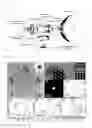
FIG. 2 shows evaluated structures of manufactured Pd core-MgO shell nanoparticles according to an embodiment of the present invention. (a) is a low magnification TEM overview of the Pd core-MgO shell nanoparticles exhibiting core-shell morphology. (b) is an HRTEM image of core (Pd) region and (c) is an HRTEM image of the shell (MgO) region. The Insets in (b) and (c) are respectively simulated images of the corresponding HRTEM images. (d) is an HAADF-STEM image of core-shell the Pd core-MgO shell nanoparticles. (e) is a distribution of Mg and Pd components in the Pd core-MgO shell nanoparticles obtained by the line-scan analysis using STEM-EDS (along the line in (d)). (f) to (h) are high resolution core-level XPS spectra for Pd 3d, Mg 2p, and O1s, respectively, from the Pd core-MgO shell nanoparticles.
GIXRD pattern of the Pd core-MgO shell nanoparticles on a silicon substrate at a fixed grazing angle of 0.2 degrees.
FIG. 4 shows TEM images of (a) Pd and (b) MgO nanoparticles, deposited separately but otherwise with identical deposition parameters for the Pd core-MgO shell nanoparticles. The image clearly shows the porosity of the oxidized Mg structures, as reported previously in NPL No. 42.
FIG. 5 is an XPS survey spectrum of the Pd core-MgO shell nanoparticles.
FIG. 6 illustrates direct engineering of the nanoparticle structure by varying the relative number densities of each vapor species in the aggregation zone. FIG. 6, (a) to (d) show low magnification STEM images and (e) to (f) show size distributions for the Pd core-MgO shell nanoparticles for various Pd/Mg sputtering power ratios; 0.66 for (a) and (e), 0.33 for (b) and (f), 0.14 for (c) and (g), and 0.11 for (d) and (h), respectively.
FIG. 7 shows AFM images of the Pd core-MgO shell nanoparticles for different Pd/Mg sputtering power ratios; (a) 0.66, (b) 0.33, (c) 0.14, and (d) 0.11.
FIG. 8 shows cyclic voltammetry (CV) measurements. In FIG. 8, (a) shows a schematic design of Pd and Pd core-MgO shell catalytic nanostructures on GC electrode. (b) shows cyclic voltammograms of room-temperature methanol oxidation on the Pd/GC and Pd core-MgO shell/GC catalysts in 1 M KOH/0.5 M methanol at 38 mV/s. (c) shows mass activities of the Pd core-MgO shell nanocatalysts for different methanol concentrations at 0.4 V (vs. Ag/AgCl). (d) shows onset peak potentials of Pd, MgO support Pd, and the Pd core-MgO shell nanocatalysts for methanol oxidation.
FIG. 9 shows current-time curves measured by chronoamperometry for Pd/GC and Pd core-MgO shell/GC nanocatalysts at −0.35 V (vs. AgCl) in N2-saturated 1 M KOH containing 0.5 M methanol.
FIG. 10 shows TEM images of (a) coalesced Pd nanoparticles and (b) the Pd core-MgO shell nanoparticles, which were used for the cyclic voltammetry measurements.
FIG. 11 shows surface area loss as a result of nanoparticle coalescence on the substrate. Particles were identified according to the original nanoparticle size (based upon the in-flight mass filter data), identified by the smallest circles. Multiples, indicating full coalescence, were also identified (middle and large sized circles). It is assumed the full coalescence only occurred in-flight, owing to the high temperatures required (NPL No. 43). Loss of surface area was then determined using the modified Frenkel method for coalesced particles (NPL No. 44), based upon the degree of interpenetration of the particles.
DESCRIPTION OF EMBODIMENTS
The present inventors have conducted a series of new experiments on heterogeneous gas-phase condensation of Pd and Mg to form Pd core-MgO porous shell nanoparticles and examined their catalytic performance towards methanol electro-oxidation.
Sputtering of Pd and Mg from two independent neighboring targets enabled heterogeneous condensation and growth of nanoparticles with controlled Pd core-MgO porous shell structure. It was found that the thickness of the shell and the number of cores within each nanoparticle can be tailored by adjusting the respective sputtering powers. The nanoparticles were directly deposited on glassy carbon (GC) electrodes (as a substrate on which the nanoparticles are to be formed), and their catalytic activity towards methanol oxidation was examined by cyclic voltammetry. The measurements indicated that the catalytic activity of nanoparticles according to the present invention is superior to conventional bare Pd nanoparticles. It was found that the improved catalytic performance is attributed primarily to inhibition of Pd cores sintering during the catalytic processes by the metal-oxide shell.
All samples were produced using a multi-target gas-aggregated sputtering chamber shown in FIG. 1 (NPL Nos. 18 and 22). FIG. 1 shows a schematic of a magnetron sputter inert gas condensation setup used for the synthesis of Pd core-MgO shell nanocatalysts.
<Synthesis Materials and Method>
Magnesium magnetron-sputtering target (Mg, purity >99.95%) and Palladium magnetron sputtering target (Pd, purity >99.95%) with dimensions of 25 mm diameter×3 mm thick were purchased from Kurt J. Lesker (PA, USA) for used in sample productions. High purity methanol, acetone, isopropanol, were purchased from Sigma-Aldrich Japan. As substrates for AFM and XPS measurements, undoped Si dice with (100) orientation and 5 mm×5 mm in size were purchased from MTI Corporation (CA, USA). Cu frames with electron transparent carbon coated grids (400 mesh) and silicon nitride membranes were purchased from Ted Pella Inc. (CA, USA), as substrates for TEM/STEM-HAADF analysis.
The Pd, MgO, and Pd core-MgO shell nanoparticles were synthesized using a magnetron-sputtering with inert-gas aggregation system (Mantis Deposition Ltd, UK), as illustrated in FIG. 1. The deposition system includes a nanocluster sputtering source, a quadrupole mass filter (QMF) and a deposition chamber. Mg and Pd sputtering targets were located side-by-side on an integrated magnetron sputtering head, as shown in the inset in FIG. 1. The desired physical and chemical properties of multicomponent hybrid nanoparticles can be tailored by controlling the size of the nanoparticles, as well as the volume fraction of each component. In the configuration according to the present invention, this was achieved by tuning the magnetron power applied on each target independently while co-sputtering. Preliminary studies were conducted to identify suitable deposition parameters for both materials, via in situ QMF feedback and deposited cluster characterization. Ar and He flow rates were 90 and 10 sccm (respectively), resulting in an aggregation zone pressure reading of 3.5×10⁻¹ mbar. The aggregation zone length was set to 100 mm. The base pressure was 1.0×10⁻⁸ mbar in the main deposition chamber. For the present disclosure, we have used three magnetrons with one palladium and two magnesium targets. A series of samples was produced, keeping the same flow of argon and helium to the magnetrons. The only parameter that was adjusted was the DC power applied to each magnetron. In the sample deposition series, the nanoparticle composition ranged from pure Mg to pure Pd, passing through four intermediate chemical compositions. Tuning of the core-shell nanoparticle size was achieved by varying the sputtering power supplied to the Pd target (7.5 W to 30 W) and Mg target (45 W to 65 W). For comparison, Mg and Pd are deposited under the same conditions, separately onto the same substrates, sequentially rather than simultaneously. The nanoparticles were deposited on either (holey) carbon coated Cu/Au grids or on 8 nm thick silicon nitride membranes. In order to obtain suitable substrate coverage, the deposition time ranged from a few minutes (for preliminary TEM structure characterizations on mono-disperse nanoparticles) up to 15 minutes (for electrochemistry studies).
<Evaluation and Characterization>
A Bruker Multimode 8 atomic force microscope (AFM) was used to analyze the topography of the samples. The AFM System, equipped with the NanoScope(R) V controller, was utilized in tapping mode using a triangular silicon-nitride AFM tip (radius <10 nm, force constant of 0.35 N/m, 65 kHz of resonant frequency).
HR-TEM studies were carried out using an FEI Titan microscope, operated at both 80 kV and 300 kV, equipped with a spherical aberration corrector for the image. In image-corrected TEM mode, the spherical and chromatic aberrations were <5 μm and 1.4 mm, respectively, with an optimum resolution of better than 0.09 nm. TEM image simulations were performed using the JEMS software package (NPL No. 41).
HR-STEM studies were performed on a FEI Titan3 G2 microscope with a Cs-corrector for the probe. STEM-HAADF and BF images were recorded at 300 kV with a convergence angle of 19.9 mrad and a camera length of 91 mm. EDX measurements were done with a Super-X detector system from Bruker with a step size of 0.06 nm and a pixel time of 0.08 s (number of cycles: 10) for the line scan.
XPS measurements were performed in a Kratos AXIS Ultra DLD Photoelectron spectrometer, with a Mg Kα anode (1253.6 eV), and a base pressure of 2×10⁻⁹ mbar. The Mg 2p, Pd 3d and O is core level narrow spectra were recorded using pass energy of 20 eV for high resolution.
Grazing incidence x-ray diffraction (GIXRD) measurements were performed in a Bruker D8 Discover XRD (thin film system), using Cu Kα radiation (40 kV/40 mA) at a fixed grazing incidence angle of 0.2 degrees.
<Electrochemical Measurements>
<Preparation of Nanoparticle Catalysts on Glassy Carbon Electrode Substrates>
Nanoparticles were directly deposited onto the electrode surface inside the Mantis UHV nanoparticle sputtering system described above. Nanoparticle dimensions and surface coverage were evaluated using TEM images, and associated mass was calculated assuming bulk density values. The estimated loading of catalyst to be 0.085 micrograms and 0.034 micrograms for Pd and Pd core-MgO shell samples, respectively.
<Electrochemical Characterization>
The electrocatalysis measurements were performed at room temperature with an electrochemical workstation 440B (CH Instruments Co., US). A conventional three-electrode system was used, which consists of a nanoparticles-modified glassy carbon (GC) electrode as the working electrode, a Pt wire as the counter-electrode, and an Ag/AgCl (3 M KCl) electrode as the reference electrode. All working solutions (1 M KOH) were purged with nitrogen for 30 min before measurements.
<Results>
The structure of a synthesized sample according to an embodiment of the present invention, i.e., Pd core-MgO shell nanocatalysts, is shown in FIG. 2. FIG. 2 shows evaluated structures of manufactured Pd core-MgO shell nanoparticles according to an embodiment of the present invention. (a) is a low magnification TEM overview of the Pd core-MgO shell nanoparticles exhibiting core-shell morphology. (b) is an HRTEM image of core (Pd) region and (c) is an HRTEM image of the shell (MgO) region. The Insets in (b) and (c) are respectively simulated images of the corresponding HRTEM images. (d) is an HAADF-STEM image of core-shell the Pd core-MgO shell nanoparticles. (e) is a distribution of Mg and Pd components in the Pd core-MgO shell nanoparticles obtained by the line-scan analysis using STEM-EDS (along the line in (d)). (f) to (h) are high resolution core-level XPS spectra for Pd 3d, Mg 2p, and O1s, respectively, from the Pd core-MgO shell nanoparticles.
The core-shell structure and uniformity are found by transmission electron microscopy (TEM), as shown in (a) in FIG. 2, with total diameters of approximately 10 nm. The cores are single crystalline Pd and the shells are polycrystalline MgO, with lattice spacings matching the literature values (NPL Nos. 21 and 23), as shown in (b) and (c), respectively, of FIG. 2. The insets of these figures present their corresponding TEM image simulations. (d) and (e) in FIG. 2 show a HAADF-STEM (z-contrast) micrograph, and extracted EDX line profile, respectively, confirming the core-shell structure.
FIG. 3 shows GIXRD pattern of the Pd core-MgO shell nanoparticles according to an embodiment of the present invention on a silicon substrate at a fixed grazing angle of 0.2 degrees. The X-ray diffraction (FIG. 3) clearly shows distinct peaks for Pd and MgO (and not any alloy phases). FIG. 4 shows TEM images of (a) Pd and (b) MgO nanoparticles, deposited separately but otherwise with identical deposition parameters. The image clearly shows the porosity of the oxidized Mg structures, as reported previously in NPL No. 42.
While TEM provides high spatial resolution on a tiny proportion of the specimen, X-ray photoelectron spectroscopy (XPS), on the other hand, allows us to gain statistical information from a wide area of the sample. FIG. 5 is an XPS survey spectrum of the the Pd core-MgO shell nanoparticles. This wide scan spectrum of FIG. 5 reveals strong characteristic signals of Pd, Mg, and O (as well as C from the substrate). Turning back to FIG. 2, (f) in FIG. 2 shows the XPS spectrum for the Pd 3d core level of the Pd core-MgO shell nanoparticles. The Pd 3d5/2 peak shifts towards higher binding energy (BE), with AE of about 0.8 eV, compared to that of Pd nanoparticles (335.5 eV). This shift in BE is due to the small amount of electron transfer from MgO to Pd, consistent with the difference in the electronegativities of Pd and Mg (Pd=2.20 and Mg=1.31) (NPL No. 24). The Pd 3d512 peak associated with PdO (336.7 eV) has not been observed in any of the acquired spectra (NPL No. 25). Mg 2p core level spectra ((g) in FIG. 2) with broad Mg 2p peaks revealed the presence of a certain amount of Mg—O bonds in the sample. The BE of the Mg 2p core level that corresponds to MgO nanoparticles (51.0 eV) is located at higher BE than for bulk metallic Mg (49.7 eV) (NPL No. 26). In addition, the O 1s spectrum is characterized by three bands ((g) in FIG. 2): two at 532.3 and 531.6 eV, which are due to the absorption of oxygen molecules on the carbon surface, and one at 530.8 eV, which corresponds to the MgO.
Given the difference in condensation and solidification temperatures (NPL Nos. 27 and 28), Pd nucleates much more quickly than Mg in a heterogeneous vapor cloud. In this situation, the pre-formed Pd clusters act as nucleation seeds for the Mg vapor, allowing rapid growth of a Mg shell on the Pd cluster, as published previously for Mg/Ti (NPL No. 13). Furthermore, the surface energy of Mg (0.8 J/m2) is significantly lower than that of Pd (2.0 J/m2) (NPL No. 29), making it energetically favorable for Mg atoms to migrate or stay on the surface of the pre-formed Pd cluster, forming a shell. Finally, upon exposure to oxygen, the shell oxidizes to form MgO (NPL Nos. 21 and 30).
Major advantages of gas-phase synthesis according to the present invention include the ease with which the deposition conditions and the controllability of resultant structures (NPL No. 18). An example showing the extent to which the nanoparticle size and structure can be engineered is demonstrated in the STEM micrographs in FIG. 6, (a) to (d). FIG. 6 illustrates direct engineering of the nanoparticle structure by varying the relative number densities of each vapor species in the aggregation zone. In FIG. 6, (a) to (d) show low magnification STEM images and (e) to (f) show size distributions for the Pd core-MgO shell nanoparticles for various Pd/Mg sputtering power ratios; 0.66 for (a) and (e), 0.33 for (b) and (f), 0.14 for (c) and (g), and 0.11 for (d) and (h), respectively. This was achieved simply by varying the quantity of active sputtering targets and the applied sputtering power, to the individual Mg and Pd magnetron heads (see FIG. 1). The results show four cases, with varying size distributions, as shown in (e) to (h) of FIG. 6. Thus, it was found that the size and internal morphology can be directly manipulated and controlled by varying the sputtering powers.
For sputtering power ratios of 0.66, 0.33, 0.14 and 0.11, the average diameters were determined to be 7.5+−1.2 nm, 9.3+−1.3 nm, 10.0+−1.5 nm, and 17.3+−2.5 nm, respectively. FIG. 7 shows AFM images of the Pd core-MgO shell nanoparticles for different Pd/Mg sputtering power ratios; (a) 0.66, (b) 0.33, (c) 0.14, and (d) 0.11, which highlight the control of the gas-phase process.
After synthesis, the catalytic properties of these the Pd core-MgO shell structures were evaluated for electrochemical oxidation of methanol. This reaction is central to the operation of direct methanol fuel cells. However, presently, utilization of this reaction is limited by its low efficiency (NPL No. 31).
For cyclic voltammetry (CV) measurements, the Pd core-MgO shell nanoparticles according to embodiments of the present invention were deposited directly onto glassy carbon (GC) electrodes (NPL No. 32), as illustrated in (a) of FIG. 8. For this investigation, the structures synthesized with sputtering ratio of 0.33 and size distribution of 9.3+−1.3 nm, as shown in (b) and (f) in FIG. 6, were analyzed. Mass current density CV curves are shown in (b) of FIG. 8. Despite the low mass, good CV signals were obtained (NPL No. 32). The general form of the curves is consistent with previous studies (NPL No. 33). Also, as shown in (c) in FIG. 8, a linear variation was observed with the methanol concentration at −0.4 V. These results indicate a reliable measurement environment. It was therefore found that these previously untested structures according to the present invention are catalytically active, demonstrating that the inert MgO shell does not passivate the internal catalytic Pd core. This in itself is a significant finding, confirming that the MgO matrix surrounding the active catalyst did not prevent reactants from arriving and products from leaving the surface to any great extent. Furthermore, it is also immediately clear that the anodic peak current density, indicative of electrocatalytic activity, is significantly increased for the core-shell structures according to the present invention, in comparison to the bare Pd nanoparticles (420 microamperes/micrograms vs 120 microamperes/micrograms, respectively). The anodic onset potential for methanol oxidation reaction (MOR) also shifted in the negative direction for core-shell particles. This is shown in (d) of FIG. 8, in which the anodic onset potentials for Pd, MgO-supported Pd, and Pd core-MgO shell structures are presented.
To evaluate the electrocatalytic stability of the as-prepared Pd core-MgO shell catalysts, long term chronoamperometric measurements were performed. FIG. 9 shows current-time curves measured by chronoamperometry for Pd/GC and Pd core-MgO shell/GC nanocatalysts at −0.35 V (vs. AgCl) in N2-saturated 1 M KOH containing 0.5 M methanol. As shown in FIG. 9, once the steady-state has been reached, the Pd core-MgO shell catalysts maintain a current density that is about twice as high as that of the conventional Pd/GC catalyst. Note that while rapid dissolution of MgO in acidic solutions has been reported previously, it is quite stable in alkaline solutions (NPL No. 20), as utilized here.
FIG. 10 shows TEM images of (a) coalesced Pd nanoparticles and (b) the Pd core-MgO shell nanoparticles, which were used for the cyclic voltammetry measurements.
By considering the insets in (b) of FIG. 8 and FIG. 10, it is evident that the noble metal coalescence behavior has been significantly reduced by the presence of the MgO shell. For the case of Pd alone, the originally discrete nature of the nanoparticles (as evidenced from the in-flight mass filter) has been lost to form larger agglomerations, with associated reduced surface area. We have roughly estimated the degree of coalescence and associated loss of surface area. This has been performed on a sample basis, using TEM micrographs. The in-situ quadrupole mass filter gives the original (pre-sintering) nanoparticle size distribution, immediately after nucleation, during flight from aggregation zone to substrate.
FIG. 11 shows the surface area loss as a result of nanoparticle coalescence on the substrate. Particles were identified according to the original nanoparticle size (based upon the in-flight mass filter data), identified by the smallest circles. Multiples, indicating full coalescence, were also identified (middle and large sized circles). It is assumed the full coalescence only occurred in-flight, owing to the high temperatures required (NPL No. 43). Loss of surface area was then determined using the modified Frenkel method for coalesced particles (NPL No. 44), based upon the degree of interpenetration of the particles. By identifying the substrate nanoparticles using the in-flight diameter and surface curvature, measurement of the degree of interpenetration, and by applying the modified Frenkel method (NPL No. 34), the loss in surface area is found to be significant, in the range of about 35% to 40%. However, the coalescence behavior of the Pd core-MgO shell structure according to the present invention is quite different. While the MgO shells in many cases come into contact, they effectively act as spacers between the Pd cores. Thus, the internal Pd cores retain their original shape and do not come into contact with each other. That the catalytic activity is not inhibited by the presence of the MgO shell is directly evidenced by the strong CV signals obtained.
The present disclosure described a newly developed controlled gas-phase synthesis method for highly active noble metal-core/porous metal oxide-shell nanocatalysts. Sputtering of Pd and Mg from two independent neighboring targets enabled heterogeneous gas-phase nanoparticle condensation with well-defined core-shell morphology. The shell did not passivate the noble metal core, and indeed the catalytic performance was improved as compared with simple Pd nanoparticles. The inhibition of Pd coalescence by the metal oxide shell was identified as one of the key contributors to the improved reactivity for methanol decomposition. These Pd core-MgO shell catalysts according to the present invention, evaluated for methanol decomposition in this study, can also be utilized for various other reactions. This simple, tunable core-shell structure and the superior performance of the nanocatalysts presented herein provides an excellent foundation to develop and optimize other noble metal-metal oxide core-shell heterogeneous nanocatalysts with tailored sizes, chemical composition, and morphologies for various catalytic reactions.
It will be apparent to those skilled in the art that various modification and variations can be made in the present invention without departing from the spirit or scope of the invention. Thus, it is intended that the present invention cover modifications and variations that come within the scope of the appended claims and their equivalents. In particular, it is explicitly contemplated that any part or whole of any two or more of the embodiments and their modifications described above can be combined and regarded within the scope of the present invention.
Claims
1. A catalyst, comprising a plurality of nanoparticles, each nanoparticle comprising:
a core made of a catalytic metal; and
a porous shell surrounding the core, made of metal oxide, the porous shell preserving a catalytic function of the core and reducing reduction of the core and coalescence of the nanoparticles.
2. The catalyst according to claim 1, wherein the catalytic metal is Pd, and the porous shell is made of MgO.
3. A catalyst, comprising nanoparticles, each nanoparticle consisting of:
a core made of Pd; and
a porous shell made of MgO, surrounding the core, a porosity of the porous shell being such that a catalytic function of Pd is preserved, and reduction of the core and coalescence of the nanoparticles are reduced.
4. A method for manufacturing Pd core-MgO shell nanoparticles, the method comprising:
forming a super-saturated vapor of Mg and a super-saturated vapor of Pd by sputtering using an Mg target and a Pd target in a vacuumed aggregation chamber;
transporting the super-saturated vapors of Pd and Mg to a vacuumed deposition chamber so that Pd nucleates and clusters first, followed by Mg nucleation and growth on the clustered Pd, surrounding the Pd cluster; and
thereafter, exposing resulting the Pd cluster surrounded by the grown Mg to oxygen to oxidize said surrounding Mg, thereby forming nanoparticles on a substrate in the deposition chamber, each of the nanoparticles consisting of one or more of a core made of Pd and a porous shell made of MgO surrounding said one or more of the core.
5. The method according to claim 4, further comprising changing a sputtering power ratio for Pd and Mg so as to create the nanoparticles of different sizes with different numbers of the core therein.
Images & Drawings included:


Sources:
- United States Patent and Trademark Office - verify current appl. status at the USPTO↗
Recent applications in this class:
- » 20250281911 2025-09-11
HYDROGENATION CATALYST - » 20250186976 2025-06-12
Exhaust Gas Purifying Catalyst - » 20250135440 2025-05-01
HYDRODEOXYGENATION CATALYSTS - » 20250128240 2025-04-24
SHELL CATALYST FOR PRODUCING ALKENYL CARBOXYLIC ACID ESTERS HAVING AN IMPROVED PD DISTRIBUTION - » 20240408580 2024-12-12
HYDROGEN PERMEABLE, INTERMETALLIC DIFFUSION BARRIERS USED IN BODY-CENTERED CUBIC METAL MEMBRANES - » 20240399343 2024-12-05
EXHAUST GAS PURIFICATION CATALYST, AND EXHAUST GAS PURIFICATION CATALYST APPARATUS FOR VEHICLES, USING SAME - » 20240278216 2024-08-22
Green method for preparing jute stem-supported catalyst - » 20240278215 2024-08-22
Method for making an unmodified jute supported catalyst - » 20240269652 2024-08-15
Method for making natural material-supported palladium catalyst - » 20240238764 2024-07-18
HYDROCARBON REDUCTION CATALYST AND VEHICLE EXHAUST GAS PURIFICATION DEVICE COMPRISING THE SAME
Recent applications for this Assignee:
- » 20230327388 2023-10-12
Ultra-low noise cryogenic microwave amplification - » 20230251224 2023-08-10
METHOD AND SYSTEM FOR IDENTIFYING STRUCTURE OF COMPOUND - » 20230183112 2023-06-15
CONCURRENT RAW AND AERATED WASTEWATER TREATMENT METHOD USING BIOELECTROCHEMICAL SYSTEM - » 20220399560 2022-12-15
BIOELECTROCHEMICAL SYSTEM FOR TREATMENT OF ORGANIC LIQUID WASTES - » 20220372584 2022-11-24
RNA APTAMER THAT SPECIFICALLY BINDS HISTAMINE - » 20220306671 2022-09-29
Oligosaccharide C-glycoside derivatives - » 20220246861 2022-08-04
Persistent luminescence emitter - » 20220212982 2022-07-07
Method of fabricating a through glass via on a suspended nanocrystalline diamond - » 20220170926 2022-06-02
Nanoplasmonic instrumentation, materials, methods and system integration - » 20220119702 2022-04-21
Composition, organic photostimulated luminescent device, luminescent method and method for designing composition for photostimulated luminescence