Portable shade provider
US20180209166A1
2018-07-26
15/932,012
2018-01-24
✅ Patent granted
US 10,426,235 B2
2019-10-01
-
-
Noah Chandler Hawk
2038-01-24
Abstract:
One embodiment of a portable shade maker comprises a collapsible cart and a telescoping and tiltable umbrella for the protection and comfort of individuals conducting activities that is lightweight and easy to relocate according to the chosen activity.The load platform can have a flange base that can accept and secure an umbrella. In addition, it can be used to carry supplies, tools, and activity equipment on its load platform to the destination location.
Applicant:
Interested in similar patents?
Get notified when new applications in this technology area are published.
Classification:
E04H15/06 » CPC main
Tents or canopies, in general; Tents combined or specially associated with other devices Tents at least partially supported by vehicles
E04H15/28 » CPC further
Tents or canopies, in general Umbrella type tents
B62B5/06 » CPC further
Accessories or details specially adapted for hand carts Hand moving equipment, e.g. handle bars
B62B5/0013 » CPC further
Accessories or details specially adapted for hand carts Protection covers, e.g. against rain
B62B5/00 IPC
Accessories or details specially adapted for hand carts
A45B17/00 » CPC further
Tiltable umbrellas
A45C13/38 IPC
Details; Accessories Luggage carriers
A45C13/385 » CPC further
Details; Accessories; Luggage carriers with rolling means
A45B11/00 » CPC further
Umbrellas characterised by their shape or attachment
A45B11/00 » CPC further
Umbrellas
B62B1/12 » CPC further
Hand carts having only one axis carrying one or more transport wheels; Equipment therefor in which the load is intended to be transferred totally to the wheels involving parts being adjustable, collapsible, attachable, detachable, or convertible
A45B2200/1009 » CPC further
Details not otherwise provided for in; Umbrellas; Sunshades combined with other objects
A45B23/00 » CPC main
Other umbrellas
A45F3/44 » CPC further
Travelling or camp articles ; Sacks or packs carried on the body Article supports adapted to be stuck into the ground
A45B2023/0012 » CPC further
Other umbrellas Ground supported umbrellas or sunshades on a single post, e.g. resting in or on a surface there below
Description
CROSS-REFERENCE TO RELATED APPLICATIONS
This application claims the benefit of PPA Ser. No. 62/499,451, filed Jan. 25, 2017 by the present inventor, which is incorporated by reference.
BACKGROUND
Prior Art
The following is a tabulation of some prior art that presently appears relevant.
| Kind | Publication | ||
| Pat. No. | Code | Date | Patentee(s) |
| U.S. patents |
| U.S. Pat. No. 9,440,668 | B | Sep. 13, 2016 | Zhaosheng Chen, Yishun Chen |
| U.S. Pat. No. 5,464,237 | A | Nov. 7, 1995 | Elena H. Saporiti |
| U.S. Pat. No. 5,575,301 | A | Nov. 19, 1996 | Mark A. Bolton |
| U.S. Pat. No. 5,876,047 | A | Mar. 2, 1999 | Macy S. Dennis |
| U.S. Pat. No. 5,857,684 | A | Jan. 12, 1999 | Gordon Liao, A |
| U.S. Pat. No. 6,726,227 | B2 | Apr. 27, 2004 | Robin Morgan |
| U.S. Pat. No. 5,857,695 | A | Apr. 17, 1997 | Stacey Lee Crowell |
| U.S. Pat. No. 7,703,469 | B2 | Apr. 27, 2010 | Warren L. Danziger |
| U.S. Pat. No. 659114 | A | Jul. 6, 1900 | Alexis Voorhies |
| Foreign patents |
| GB 2137937 | A | Aug. 14, 1982 | Michael Noel Warnes, Malcolm H. King |
Existing solutions used to protect individuals from the sun and rain have been either fixed or mobile. The fixed solutions limits the shade benefit to a single location. Other limitations are included for the more relevant patents.
Prior art reveals mobile shelters on a limited scale. Solutions such as U.S. Pat. No. 9,440,668—Umbrella Table Folding Cart, utilizes a 4 wheeled wagon that receives an umbrella through a hole in the center of the table. The width of the table reduces the shaded space for an individual to perform various athletic or working activities underneath the protection of the umbrella. Additionally, a second disadvantage is the weight and size of the table which lessens it ease of portability.
Another prior art U.S. Pat. No. 5,464,237 Folding Cart describes a foldable cart for transporting camping, beach equipment to a location otherwise not easily accessible by vehicle. The stated intention here is for transporting equipment. It is not meant for conducting various activities such as swinging a golf club or shooting at an archery or gun range. Again the width of the table would lessen the ability to get protection from the umbrella.
The prior art U.S. Pat. No. 5,575,301 Mobile Shelter describes a movable canopy found mostly at Country Club and College Golf Team destinations. The disadvantages here are a much higher cost for such a device and the inability to easily transport such a device by an individual.
The prior art U.S. Pat. No. 5,876,047 A a utility cart that includes two or more tables that are hinged to the cart which can accommodate two umbrellas. The said utility cart does not collapse the wheels and the umbrellas are intended to provide shade for the cart and its components. Again, the device leave little room for an individual conducting an activity.
Another prior art is a collapsible golf cart U.S. Pat. No. 5,857,684 A which is only used to protect the user while pulling the cart. The user must then step away from this protection in order to have sufficient room to swing.
Humans have been protecting themselves from both the heat and the harmful rays of the sun for a very long time. The parasol and umbrella have served the useful purpose of protecting the human by holding the umbrella while standing or walking. They can also be useful for people sitting underneath one on their deck or at a restaurant.
For people that indulge in activities that require the use of both hands such as golf, gardening, archery, photography, painting and other outdoor activities, there are not many choices.
SUMMARY
The purpose of the shade provider embodiment presented here is to make up for the shortcomings of current existing inventions that provide the protection of shade. In accordance with one embodiment, a portable shade provider comprises a telescoping and tiltable umbrella attached to a push cart that has fold-in wheels and collapsible handle. The load platform utilizes either a weight on said platform or anchoring devices deployed around the flat bracing of the load platform to lessen effects created by the wind.
Advantages
Accordingly, there are several advantages to the portable shade provider presented with this patent application. This said portable shade provider is less expensive than the canopies used at some golf ranges. The said shade provider is easy to set up. It utilizes a larger beach size umbrella/parasol that is of sufficient size to protect most of one's exposed body. The umbrella can tilt to adjust for sun movement, and be adjusted higher to allow more room to conduct certain activities. It also can be collapsed easily to fit in one's vehicle trunk. Another advantage is that said umbrella will reduce exposure to UV rays that are known to cause cancers that both kill and cause the skin to age and wrinkle.
Finally, another important advantage of using this shade provider is the cooler environment that it provides. Many individuals will be more productive and less prone to error when their activity is conducted in a more comfortable environment. Owners of businesses such as a golf driving range will enhance their facilities by providing this benefit to those who practice their golf swings. There are many other activities that will be made more comfortable and safer with this provider of shade. To name a few; gardening, tennis between sets, outdoor photography, and painters. There are also many outdoor activities around the house that can be made more comfortable and safer. These and many other activities could benefit from less exposure to UV rays and made more comfortable by the 10-15 degree cooling effect of shade.
DRAWINGS
Figures
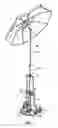
FIG. 1 Shows various aspects of the Portable Shade Provider with a tiltable umbrella attached to a foldable pushcart in accordance with one embodiment.
FIG. 2 Shows the foldable pushcart in its deployed position.
FIG. 3 Shows the foldable pushcart in the closed position.
FIG. 4 Shows the foldable pushcart in it's partially deployed/closed position
FIG. 5 Shows the double tube connector.
FIG. 6 Shows the flange base.
FIG. 7 Shows various anchoring embodiments—weights were not included in drawing since they could take on any shape, size and material that would fit on the load platform.
| Drawings Reference Numerals |
| 1. | Umbrella | 2a. | Umbrella telescoping pole |
| 2b. | Auxiliary telescoping pole | 3. | Double tube connector |
| 4. | Adjustment lock | 5. | Flange base |
| 6. | Retractable handlebar | 7. | Telescoping rod |
| 8. | Snap lock | 9. | Crossbar |
| 10. | Sliding handlebar sockets | 11. | Socket seat |
| 12. | Pivotable connector | 13. | Load Platform |
| 14. | Load platform hinge | 15. | Wheel frame |
| 16. | Gear assembly | 17. | Wheel |
| 18. | Handle cushion | 19. | Outer tube of telescoping rod |
| 20. | Inner tube of telescoping rod | 21. | Main Frame |
| 22. | Adjustment nut and bolt | 23. | Locking pin |
| 24. | Set Screw | 25. | Load platform bracing |
| 26. | Anchoring stakes | 27. | Anchoring weights |
| 28. | Push lock | ||
DETAILED DESCRIPTION
FIG. 1, FIG. 2, FIG. 3
First Embodiment
One embodiment of the portable shade provider is shown in FIG. 1 wherein an umbrella 1 with a tiltable and telescoping pole 2A attaches to an auxiliary telescoping pole 2b that is secured to the flange base 5 which is a attached to the load platform 13. To secure said umbrella, a double tube connector 3 available from RK Rose+Kriegner, Minden, Germany is attached to the top handle 6 of the pushcart FIG. 1. The auxiliary pole 2b is then passed through said double tube connector 3 to said flange base 5 of the pushcart FIG. 2. Various means of staking 26 are then employed around the load platform spokes 28 to secure the Portable Shade Protector to the ground or pavement.
OPERATION
FIGS. 1, 2, 3, 4, 5, 6
The manner of operating the portable shade provider is to first push down on the load platform 13 which will engage the gear assembly 16 simultaneously pushing out the wheels 17. Next, disengage the spring aided snap lock 8 and pull up on the top handlebar 6 until it snaps into place on the top crossbar 9. At this time, anchor the load platform 13 to the earth by means of stakes and/or weights 26 by deploying said stakes around the load platform bracing 25. Weights 26 can be deployed by laying them on the load platform 13.
Next, pass the auxiliary umbrella pole 2b through the double tube connector 3 to fit into the flange base 5. Now secure 2b to the flange base by tightening the set screw 24 and/or threading the locking pin 23 through the holes in the wall of said flange base 5 and the lined up holes at the base of said auxiliary telescoping pole 2b. Finally, take umbrella 1 and its telescoping pole 2a and place it over the slightly smaller diameter of said umbrella telescoping pole 2b and engage the adjustment lock 4 of adjustment pole 2b. Adjust the tilt and height of the umbrella 1 to accommodate both the user and the activity.
Claims
I claim:1. A shade producing apparatus comprising: a pushcart member having a collapsible handle and wheels that fold in simultaneously; an umbrella member having a telescoping and tiltable pole. This umbrella pole can be attached to a telescoping auxiliary pole. The 2 poles then can be secured to a flange base that is mounted and secured to the load platform of said pushcart.
2. The shade producing embodiment of claim 1 further comprises a double tube clamp that is adjustable and secured to the top of said pushcart handlebar.
3. The shade producing embodiment of claim 1 further comprises a number of multipronged anchoring staples that secure the loading platform to the ground.
4. The shade producing embodiment of claim 1 further comprises a fitted weight that can be fitted on the top of the load platform
5. The said telescoping auxiliary pole of claim 1 is secured to the flange base using a locking pin threaded through the holes in both said pole and said flange base.
6. The said telescoping auxiliary pole of claim 1 is secured using a set screw that is part of said flange base.
7. The said flange base of claim 1 has inside threads to accept a threaded pipe, wherein said threaded pipe can be put through a hole cut in the load platform and secured by a nut on the bottom of said load platform.
8. The said flange base of claim 1 is secured to the load platform using nuts and bolts.
9. The telescoping auxiliary pole can be put through a pole hole cut in the load platform and then be secured by using a locking pin put through holes made At the bottom of said auxiliary pole.
Images & Drawings included:


Sources:
- United States Patent and Trademark Office - verify current appl. status at the USPTO↗
Similar patent applications:
Recent applications in this class:
- » 20250283346 2025-09-11
ROOFTOP TENT ANNEX SYSTEM - » 20250283345 2025-09-11
CANOPY FOR ATTACHMENT TO HELICOPTER ROTOR BLADES - » 20250270840 2025-08-28
Collapsible Tent Assembly - » 20250250814 2025-08-07
SHELTER SYSTEM HAVING DEPLOYABLE PLATFORM - » 20250237079 2025-07-24
REAR MOUNT TENT - » 20250163719 2025-05-22
ATTACHMENT DEVICE FOR INSTALLING ON A VEHICLE ROOF - » 20250154789 2025-05-15
TRUCK BED CANOPY DEVICE - » 20250137281 2025-05-01
TRUCK BED TENT - » 20250137280 2025-05-01
CARBON FIBER ROOFTOP TENT - » 20250122745 2025-04-17
OUTDOOR BLANKET AND VEHICLE PRIVACY CURTAIN