Wall-based Rolling Ball Sculpture
US20180236350A1
2018-08-23
15/899,315
2018-02-19
Abstract:
A rolling ball sculpture is comprised of modular track parts, connected together to form a contiguous pathway for balls. Magnetic wall mount parts are assembled to a wall in an array with even spacing in order to hold magnetic support pieces that may be moved into various locations. Track pieces may be held by support pieces that mount onto the moveable supports that are magnetically mounted to permanent magnetic pieces. Track parts include straight parts, turns, and mechanisms such as chimes, switches for diverting balls along differing paths, funnels, and conveyor parts that lift balls to the top of the sculpture. Parts may be constructed of 2-dimensional parts that may be cut or stamped from flat materials, such as laser-cut plywood.
Inventors:
- Andrew Lewis Johnston 5 🇺🇸 Redwood City, CA, United States
- Keith Barker Johnston 1 🇺🇸 Eugene, OR, United States
Interested in similar patents?
Get notified when new applications in this technology area are published.
Classification:
A63F7/3622 » CPC main
Indoor games using small moving playing bodies, e.g. balls, discs or blocks; Accessories; Details; Constructional details not covered by groups - , i.e. constructional details of rolling boards, rims or play tables , e.g. frame, game boards, guide tracks Specially shaped rolling boards for the balls, e.g. ball tracks
A63F2250/50 » CPC further
Miscellaneous game characteristics Construction set or kit
A63H18/021 » CPC further
Highways or trackways for toys ; Propulsion by special interaction between vehicle and track; Construction or arrangement of the trackway Flexible tracks; Fluid-pressure-actuated tracks
A63H18/023 » CPC further
Highways or trackways for toys ; Propulsion by special interaction between vehicle and track; Construction or arrangement of the trackway Track control means, e.g. switches
A63F7/36 IPC
Indoor games using small moving playing bodies, e.g. balls, discs or blocks; Accessories; Details Constructional details not covered by groups - , i.e. constructional details of rolling boards, rims or play tables , e.g. frame, game boards, guide tracks
A63H5/00 » CPC further
Musical or noise- producing devices for additional toy effects other than acoustical
A63H18/02 IPC
Highways or trackways for toys ; Propulsion by special interaction between vehicle and track Construction or arrangement of the trackway
A63H33/26 » CPC further
Other toys Magnetic or electric toys
Description
REFERENCE TO RELATED APPLICATIONS
This application claims an invention which was disclosed in Provisional Application No. 62/460,840, filed Feb. 19, 2017, entitled “Wall-based 2-D cut wood Rolling Ball Toy Kit”. The benefit under 35 USC § 119(e) of the United States provisional application is hereby claimed, and the aforementioned application is hereby incorporated herein by reference.
BACKGROUND OF THE INVENTION
Marble toys have existed for a long time. Generally, a marble starts at the top of a track and rolls downward along a path, sometimes winding and sometimes traveling through various mechanisms along the way down. In some cases the path is modular and/or adjustable in some way so that a user can enjoy making changes to a design.
Some examples of such toys are:
- “Rolling Ball and Track Toy” Stair, U.S. Pat. No. 2,532,521, issued Dec. 5, 1959
- “Marble Runway” Cook, U.S. Pat. No. 2,729,914, Jan. 10, 1956
- “Knockdown Marble Railway Toy” Grosser, U.S. Pat. No. 3,145,501, Aug. 25, 1964
- “Jump Chute Marble Race Toy” Klitsner, U.S. Pat. No. 4,874,342, Oct. 17, 1989
- “Marble race toy with elevator and supporting infrastructure” U.S. Ser. No. 08/657,856, Sep. 1, 1998
- “Tube toy and method”, Gilman, U.S. Ser. No. 08/326,278, Sep. 19, 1995
- “Suspended runway”, Quercetti, EP1427498B1, Dec. 17, 2008
- “Track Segments Providing A Convoluted Path”, Horowitz, U.S. Pat. No. 8,568,188B2, Oct. 29, 2013
- “Wall mounted toy track set”, O'Connor, U.S. Pat. No. 8,608,527B2, 2015 Pending
All of these examples incorporate a track with an upper starting point, and a pathway down to an endpoint below. Some require manual operation to drop balls into the top of the track, while others incorporate a means of conveying marbles back up to the top starting position.
As evidenced by these examples of prior art, the concept of a rolling ball sculpture has long been appreciated. While there have been many attempts to enable users to re-configure track designs, many of these attempts result in a limited ability to re-configure track. Oftentimes the device is assembled on a table or floor at least temporarily dedicated for the purpose. These concepts also generally lack forethought as to ease of assembly, as well as ease of manufacturing.
BRIEF SUMMARY OF THE INVENTION
Objects of the present rolling ball sculpture are:
to semi-permanently mount magnetic components to a wall in an array with even spacing;
to construct a track comprised of modular track components;
to align modular track components to one another with interlocking features;
to rigidly connect modular track pieces to one another with u-shaped clips;
to mount the track to a wall using support members attached to wall via magnetic mounts;
to enable re-configuration of modular track pieces to one another and to wall mounts;
to convey balls to the top of the sculpture using a motorized conveyor
The rolling ball sculpture is comprised of modular track parts which connect to one another using u-shaped clips. Said modular track parts align to one another with interlocking features to ensure that a rolling ball does not get stuck in transition between track parts. An array of magnetic wall mount parts are assembled to a wall in an array with even spacing. Support pieces with magnets may be moved into various locations where they latch to the magnetic wall mount parts magnetically. Track pieces may be connected to support pieces that mount onto moveable supports that are magnetically mounted to permanent magnetic pieces. Track parts include straight parts, turns, and mechanisms such as chimes, switches for diverting balls along differing paths, funnels, and conveyor parts that lift balls to the top of the sculpture. The parts may be constructed of 2-dimensional parts that may be cut or stamped from flat materials, such as laser-cut plywood. In this manner a large sculpture kit could be flat packaged into a relatively small box. A motorized conveyor belt moves balls back to the top of the sculpture to enable continuous motion of balls along the track.
BRIEF DESCRIPTION OF THE SEVERAL VIEWS OF THE DRAWING
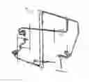
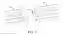
FIG. 1 is a side view of one configuration of the wall-mounted rolling ball sculpture
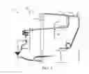
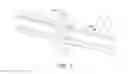
FIG. 2 is a side view of an array of magnetic wall mount parts
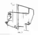
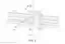
FIG. 3 shows an isometric view of the wall-mounted rolling ball sculpture
FIG. 4 shows a magnetic support before it latches to magnetic wall mounts
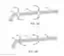
FIG. 5A shows modular track parts and assembly clips prior to assembly
FIG. 5B shows modular track parts and assembly clips after assembly
FIG. 6 shows interlocking alignment features between modular parts
FIG. 7 shows assembly clip holding modular track parts together
FIG. 8 shows track support part holding modular track part
FIG. 9 shows spiral track segment comprised of 80-degree turn parts
FIG. 10 shows motorized conveyor for lifting balls to top of sculpture
FIG. 11A shows modular track pieces prior to assembly
FIG. 11B shows assembled modular track part
DETAILED DESCRIPTION OF THE INVENTION
The rolling ball sculpture 100 shown in FIG. 1 is comprised of modular track components 110 mounted on track support members 106 which are mounted to magnetic support parts 102, which magnetically latch to magnetic wall mount parts 101.
An array of evenly spaced magnetic wall mount parts 101 is shown in FIG. 2. Each part is comprised of a disc containing a high-strength magnet 104 located in the center of the disc. Wall mount discs 101 are mounted to the wall with adhesive, preferably a non-destructive removable double-sided adhesive tape. A wall containing this array of discs is prepared to receive magnetic support structures which provide a foundation for mounting track support parts.
FIG. 3 FIG. 3 shows an isometric view of the rolling ball sculpture 100.
FIG. 4 shows a magnetic support structure 102, with high-strength magnet 104, in a position just before latching magnetically with the wall mounted magnetic discs 101, which also contain high-strength magnets 104.
FIG. 5A
FIG. 5A shows modular track parts 110 prior to assembly with assembly clips 105
FIG. 5B
FIG. 5B shows assembled modular track components 110 held together with assembly clips 105. Assembly clips slide around end pieces of modular track parts, coupling them together to form a continuous track.
FIG. 6 shows interlocking alignment features 103 that act to position modular parts 110 relative to one another in such a manner as to ensure smooth transition of a ball rolling from one part to another.
FIG. 7 Modular track parts 110 are held together via assembly clips 105.
Modular track part 110 is supported by track support part 106 which is hooked onto magnetic support part 102.
FIG. 9 illustrates the versatility of the modular track design. In assembling a group of 80-degree modular track parts 110, introducing a slight rotation with assembly of each successive part can achieve a spiral segment of track 120.
FIG. 10 shows a motorized conveyor belt 108 that returns balls 109 from the bottom of the sculpture back to the top.
FIG. 11A
FIG. 11A shows pieces 111, 112 that can be assembled to form a modular track part 110. These pieces can be made entirely from 2-D materials. Said materials may be flat packaged prior to parts being punched out, in order to achieve efficient packaging design.
FIG. 11B
FIG. 11B shows an assembled modular track part 110.
Claims
We claim:1. A kinetic sculpture of the rolling ball type comprising:
a plurality of individual parts including:
a modular wall-mounted support structure composed of an evenly-spaced array of magnetic mounts, semi-permanently adhered to the wall;
support struts with magnets at either end which latch magnetically to said magnetic mount parts;
various track support parts which mount to said support struts via mechanical interlocking features and which support said track parts;
a plurality of modular interlocking track parts which mount to said support struts and which align to one another to form a contiguous track to accommodate rolling balls;
2. The kinetic sculpture in claim 1, wherein said modular interlocking track parts are held together with u-shaped press-fit clips that hold parts together.
3. The kinetic sculpture in claim 1, wherein all parts are comprised primarily of flat pieces that can be manufactured from laser-cut sheet materials such as wood, plastic, metal, etc.
4. The kinetic sculpture in claim 1, wherein the modular parts are aligned to one another with interlocking features to ensure smooth transitions of the ball between parts.
Images & Drawings included:


Sources:
- United States Patent and Trademark Office - verify current appl. status at the USPTO↗
Recent applications in this class:
- » 20240374987 2024-11-14
Start and End Components and Methods of Making Same - » 20240009551 2024-01-11
MARBLE RACING GAME - » 20230051692 2023-02-16
MAGNETIC CONNECTORS AND COUPLED TRACK SEGMENTS FOR ROLLING BALLS DOWN A VERTICAL SURFACE - » 20220203216 2022-06-30
Start and end components and methods of making same - » 20220047936 2022-02-17
MARBLE RACING TRACK - » 20220032170 2022-02-03
Magnetic connectors and coupled track segments for rolling balls down a vertical surface - » 20200254329 2020-08-13
Modular ball track system - » 20190038963 2019-02-07
Modular marble toy kit - » 20130320619 2013-12-05
BALL TRACK SET - » 20130252506 2013-09-26
Marble Race Game