Regenerative fuel cell
US20180351193A1
2018-12-06
16/056,116
2018-08-06
✅ Patent granted
US 10,749,201 B2
2020-08-18
-
-
Emmanuel E Duke
Invention to Patent Services | Alex Hobson
2038-08-06
Abstract:
A regenerative fuel cell produces hydrogen that is stored in a reservoir on the storage side of a membrane electrode assembly when operating in a hydrogen pumping mode and this stored hydrogen is reacted and moved back through the membrane electrode assembly to form water when operating in a fuel cell mode. A metal hydride forming alloy may be configured in the hydrogen storage reservoir and may be coupled to the membrane electrode assembly. An integral metal hydride electrode having a metal hydride forming alloy may be configured on the storage side of the membrane electrode assembly and may have a catalyst or an ion conductive media incorporated therewith.
Inventors:
- Bamdad Bahar 94 🇺🇸 Georgetown, DE, United States
- Jacob Zerby 12 🇺🇸 Harbeson, DE, United States
- Scott Fackler 1 🇺🇸 Harrington, DE, United States
Assignee:
- Xergy Inc. 12 🇺🇸 Harrington, DE, United States
Applicant:
Interested in similar patents?
Get notified when new applications in this technology area are published.
Classification:
C01B3/0031 » CPC further
Hydrogen; Gaseous mixtures containing hydrogen; Separation of hydrogen from mixtures containing it ; Purification of hydrogen; Reversible uptake of hydrogen by an appropriate medium, i.e. based on physical or chemical sorption phenomena or on reversible chemical reactions, e.g. for hydrogen storage purposes ; Reversible gettering of hydrogen; Reversible uptake of hydrogen by electrodes characterised by the uptaking medium; Treatment thereof Intermetallic compounds; Metal alloys; Treatment thereof
H01M8/04067 » CPC further
Fuel cells; Manufacture thereof; Auxiliary arrangements, e.g. for control of pressure or for circulation of fluids related to heat exchange Heat exchange or temperature measuring elements, thermal insulation, e.g. heat pipes, heat pumps, fins
H01M8/04201 » CPC further
Fuel cells; Manufacture thereof; Auxiliary arrangements, e.g. for control of pressure or for circulation of fluids; Arrangements for control of reactant parameters, e.g. pressure or concentration Reactant storage and supply, e.g. means for feeding, pipes
H01M2008/1095 » CPC further
Fuel cells; Manufacture thereof; Fuel cells with solid electrolytes Fuel cells with polymeric electrolytes
C01B3/00 IPC
Hydrogen; Gaseous mixtures containing hydrogen; Separation of hydrogen from mixtures containing it ; Purification of hydrogen
C01B3/00 IPC
Hydrogen; Hydrides; Water; Synthesis gas from hydrocarbons
C01B3/065 » CPC further
Hydrogen; Gaseous mixtures containing hydrogen; Separation of hydrogen from mixtures containing it ; Purification of hydrogen; Production of hydrogen or of gaseous mixtures containing a substantial proportion of hydrogen by reaction of inorganic compounds containing electro-positively bound hydrogen, e.g. water, acids, bases, ammonia, with inorganic reducing agents from a hydride
C01B3/06 IPC
Hydrogen; Gaseous mixtures containing hydrogen; Separation of hydrogen from mixtures containing it ; Purification of hydrogen; Production of hydrogen or of gaseous mixtures containing a substantial proportion of hydrogen by reaction of inorganic compounds containing electro-positively bound hydrogen, e.g. water, acids, bases, ammonia, with inorganic reducing agents
H01M8/1004 » CPC further
Fuel cells; Manufacture thereof; Fuel cells with solid electrolytes characterised by membrane-electrode assemblies [MEA]
H01M8/18 IPC
Fuel cells; Manufacture thereof Regenerative fuel cells, e.g. redox flow batteries or secondary fuel cells
H01M8/04089 » CPC further
Fuel cells; Manufacture thereof; Auxiliary arrangements, e.g. for control of pressure or for circulation of fluids; Arrangements for control of reactant parameters, e.g. pressure or concentration of gaseous reactants
H01M8/04216 » CPC further
Fuel cells; Manufacture thereof; Auxiliary arrangements, e.g. for control of pressure or for circulation of fluids; Arrangements for control of reactant parameters, e.g. pressure or concentration; Reactant storage and supply, e.g. means for feeding, pipes characterised by the choice for a specific material, e.g. carbon, hydride, absorbent
H01M8/04007 » CPC further
Fuel cells; Manufacture thereof; Auxiliary arrangements, e.g. for control of pressure or for circulation of fluids related to heat exchange
H01M8/186 » CPC main
Fuel cells; Manufacture thereof; Regenerative fuel cells, e.g. redox flow batteries or secondary fuel cells; Regeneration by electrochemical means by electrolytic decomposition of the electrolytic solution or the formed water product
H01M8/04082 IPC
Fuel cells; Manufacture thereof; Auxiliary arrangements, e.g. for control of pressure or for circulation of fluids Arrangements for control of reactant parameters, e.g. pressure or concentration
H01M8/1018 IPC
Fuel cells; Manufacture thereof; Fuel cells with solid electrolytes characterised by the electrolyte material Polymeric electrolyte materials
Description
CROSS REFERENCE TO RELATED APPLICATIONS
This application is a continuation in part of U.S. patent application Ser. No. 15/403,299, filed on Jan. 11, 2017, entitled, Advanced Metal Hydride Heat Transfer Systems Utilizing An Electrochemical Compressor and currently pending, and this application claims the benefit of U.S. provisional patent application No. 62/541,605, filed on Aug. 4, 2017 and entitled, Regenerative Fuel Cell; the entirety of both applications is hereby incorporated by reference herein.
STATEMENT OF GOVERNMENT LICENSE RIGHTS
This invention was made with government support under Department of Energy grant DE-SC0015923. The government has certain rights in the invention.
BACKGROUND OF THE INVENTION
Background
The present invention relates to a regenerative fuel cell, wherein a single cell acts as both an electrolyzer and as a fuel cell, and hydrogen is generated from a fluid stream and particularly from a gas stream, such as air.
Conventionally, regenerative fuel cells are run with liquid water on the anode during electrolysis hydrogen generation mode. Water is fed to the anode side of the cell, a voltage is applied to the cell, and the water is split causing protons to travel through the ion exchange media and oxygen to be released from the anode. The protons recombine with electrons to form hydrogen on the cathode side, and the hydrogens are stored either as high pressure gas or as a metal hydride. A load is then hooked up to the system, and the hydrogen that was stored in the cathode side, now the anode side of the fuel cell, during electrolysis form protons, which travel through the ion exchange media, and electrons. Oxygen is fed on the cathode side of the fuel cell and recombines with the protons and electrons to form water and energy. The cell is run reversibly to both produce and consume hydrogen, which leads to catalyst instability. There are also issues of flooding the hydrogen generation side.
Generating hydrogen from moisture in the air remedies both issues. Liquid water is not in contact with the reversible catalyst, which reduces the degradation and improves the lifetime of the system. Flooding of the cathode is not an issue, as water is limited when utilizing moisture in the air.
SUMMARY OF THE INVENTION
An exemplary regenerative fuel cell may have extended life and be less prone to flooding by reacting with a gas as opposed with a fluid source. Humidity from ambient air or an air stream may be reacted on the source side of the membrane electrode assembly to produce and pump hydrogen to the storage side of the membrane electrode assembly. Utilizing a gas stream reduces flooding and improves the life of the catalyst of the electrodes in the membrane electrode assembly. Hydrogen pumped by the regenerative fuel cell may be stored in hydrogen storage reservoir, such as a tank including a high pressure tank. The membrane electrode assembly may pump the hydrogen to the reservoir and a compressor or pump and one or more valves may be used to increase the pressure within the reservoir. The source side of the membrane electrode assembly may receive ambient air and a filter may be used to remove any contaminates that might prematurely foul or de-active the catalyst. An air moving device, such as s fan or pump may force the source gas stream into the regenerative fuel cell.
An exemplary reservoir may comprise a metal hydride forming alloy, or a metal alloy that forms a metal hydride when it absorbs hydrogen. The metal hydride may be configured or coupled with the membrane electrode assembly of the regenerative fuel cell. In an exemplary embodiment, the electrode on the storage side of the membrane electrode assembly is an integral metal hydride electrode that comprises a metal hydride forming alloy.
In an exemplary embodiment, a metal hydride heat transfer system is coupled with or integrated with the regenerative fuel cell, as described herein. Exemplary metal hydride heat transfer systems are described in U.S. patent application Ser. No. 15/403,299, filed on Jan. 11, 2017 and entitled, Advanced Metal Hydride Heat Transfer Systems Utilizing An Electrochemical Compressor, to Xergy Inc., the entirety of which is incorporated by reference herein. The regenerative fuel cell of the present invention may provide hydrogen to a metal hydride heat transfer system or may act as one of the heat transfer devices of the metal hydride heat transfer system. A metal hydride heat transfer system may leak hydrogen and a regenerative fuel cell system, as described herein may provide make up hydrogen as required.
An exemplary membrane electrode assembly may comprise an ion conducting layer, such as a cationic conductive material that can transport protons. An example of such a material is an ionomer. An exemplary ion conducting layer may be thin to improve the rate of transport of protons and may comprise a support material to enable very thin layers. For example, a support material may comprise a fluoropolymer material that is porous, such as an expanded polytetrafluoroethylene.
It is important to recognize that metal hydride need specific pressures to absorb hydrogen, and other specific pressures, generally lower than the absorption pressures to desorb the hydrogen. The ratio of the absorption to desorption pressure Higher efficiencies are gained when the pressure ratio of the pressure of the output gas to the pressure of the incoming gas is minimized. In one embodiment, the pressure ratio of the electrochemical compressor is as high as 20 or more, or about 30 or more, 35 or more and any range between and including the pressure ratios provided. However, lower ratios are better, and more efficient, wherein they require less power. Some metal hydrides such as those in Tables 1 to 4. LaNi4.8Al02 are reported to have P(low) of 2.47 atmospheres and a P(high) of 35.84 atmospheres, a pressure ratio requirement of 14.51; another hydride Mm Ni(4.7) Fe(0.3) has a P(L) of 1.29 atmospheres and a P(H) of 12.14 i.e. a ratio of 9.41.
| TABLE 1 | |||
| COMPOSITION | A | B | COMPOUNDS |
| A2B | Mg, Zr | Ni, Fe, Co | Mg2Ni, Mg2Co, |
| Zr2Fe | |||
| AB | Ti, Zr | Ni, Fe | TiNi, TiFe, ZrNi |
| AB2 | Zr, Ti, Y, La | V, Cr, Mn, Fe, | LaNi2, YNi2, YMn2, |
| Ni | ZrCr2, ZrMn2, ZrV2, | ||
| TiMn2 | |||
| AB3 | La, Y, Mg | Ni, Co | LaCo3, YNi3, |
| LaMg2Ni9 | |||
| AB5 | Ca, La, Rare | Ni, Cu, Co, Pt, | CaNi5, LaNi5, CeNi5, |
| Earth | Fe | LaCu5, LaPt5, LaFe5 | |
| TABLE 2 | |||
| Hydride | ΔH. cal/mol | ΔS. cal/mol · K | m · g/mole |
| V0.95Cr0.01 | −8930 | −33.3 | 109.8 |
| V0.925Cr0.975 | −8680 | −33.4 | 128.3 |
| V0.9Cr0.1 | −7970 | −32.0 | 120.9 |
| NiZr | −7270 | −17.1 | 112.0 |
| V0.83Cr0.13 | −7100 | −30.0 | 347.3 |
| MNi4.3Al0.06Fe0.05 | −7420 | −26.5 | 290.0 |
| LaNi5 | −7380 | −25.8 | 175.8 |
| Fe0.85Mn0.15Ti | −7040 | −25.6 | 220.0 |
| PrNi5 | −6940 | −28.5 | 220.0 |
| MNi4.5Al0.03 | −6700 | −25.2 | 281.2 |
| FcTi | −6700 | −25.3 | 242.4 |
| NdNi5 | −6650 | −27.8 | 167.8 |
| MNi4.13FE0.83 | −6000 | −25.0 | 308.4 |
| Zr(Fe0.73Cr0.25)2 | −5920 | −21.9 | 206.2 |
| Ca0.7M8.3Ni5 | −6400 | −24.0 | 168.8 |
| Ca0.5M0.5Ni5 | −6160 | −24.8 | 168.8 |
| Ca0.4M0.6Ni5 | −6040 | −25.2 | 168.8 |
| Ca0.2M0.8Ni5 | −5800 | −26.0 | 168.8 |
| Ce0.5La6.5Ni2.5Cu2.5 | −5500 | −20.7 | 393.0 |
| CeNi5 | −5300 | −26.7 | 198.5 |
| CeNi4.5Al0.5 | −5230 | −22.0 | 220.1 |
| MNi5 | −5000 | −23.1 | 203.1 |
| ZrMn2Cu | −6170 | −13.8 | 175.0 |
| ZrMn | −4710 | −14.7 | 200.0 |
| ZrMn | −4400 | −12.5 | 200.0 |
| Zr0.5Ti0.2MnFe | −2660 | −9.4 | 175.0 |
| indicates data missing or illegible when filed |
| TABLE 3 | ||||
| Mass | Capacity | |||
| Alloys used | Type | (kg) | (kW) | COP |
| LaNi5/MmNi4.15Fe0.85 | R | 3.6 | 0.6 | — |
| LaNi4.7Al0.3/MmNi4.15Fe0.85/ | R | 3.6 | 0.6 | — |
| LaNi4.7Al0.3/LaNi4.85Al0.15 | R | 90 | — | 0.42 |
| LaNi4.65Al0.35/MmNi4Fe | R | 40 | 1.75 | — |
| LaNi4.65Al0.35/MmNi4Fe | R | 40 | 1.3 | 0.3 |
| LaNi4.7Al0.3/MmNi4.17Fe0.55 | R | 90 | 22.8 | — |
| LaNi5/LaNi4.7Al0.3 | HP | 20 | 0.6 | — |
| LaNi4.7Al0.3/MmNi4.85Fe0.35 | HP | 1.0 | — | — |
| MmNiMnAl/MmNiMnCo | HP | 64 | 3.0 | — |
| MmNi4.4Mn0.5Al0.05Co0.05 | R | 48 | 4.6 | — |
| MmNi4.7Mn0.35Lm0.95Ni5 | ||||
| LaNi4.5Al0.5/(CFM)Ni5 | R | 2.6 | — | 0.33 |
| Zr0.9Ti0.3Cr0.9Fe1.1/ | R | 4.5 | 0.683 | — |
| Zr0.9Ti0.1Cr0.6Fe1.4 | ||||
| ZrMnFe/MmNi4.5Al0.5 | R | 1.5 | 0.1 | 0.2-0.4 |
| LaNi4.7Al0.3/MmNi4.15Fe0.85 | R | — | — | — |
| LaNi4.5Al0.4/MmNi4.15Fe0.15 | HP | 3.0 | 0.15-0.2 | .17-0.2 |
| LaNi5 | C | 1 | 1.5 (150 S | — |
| cooling) | ||||
| Ca0.4Mm0.5Ni5 | C | 1 | 2.2 (150 s | — |
| cooling) | ||||
| LaNi4.5Al0.4 | R | 3 | 0.15 | — |
| MmNi4.15Fe0.85 | ||||
| Zr0.9Ti0.3Cr0.55Fe1.45 | C | 1 | 0.41 | 1.8 |
| TABLE 5 | |||||||
| alloy | ΔH | ΔS | cL | c8 | d(InPd)/dc | In(Pd/Pd) | M |
| LaNi5 | 30.8 | 0.108 | 0.07 | 1 | 0.13 | 0.13 | 432.456 |
| MmNi4.15Fe0.85 | 25.3 | 0.105 | 0.1 | 0.75 | 0.36 | 0.17 | 431.373 |
| V | 40.1 | 0.1407 | 1 | 2 | 0.15 | 0.45 | 50.942 |
| (V0.0Ti0.1)0.95Fe0.85 | 43.2 | 0.1396 | 1 | 1.95 | 0.45 | 0.8 | 50.898 |
| CaNi5 | 31.9 | 0.101 | 0.2 | 0.75 | 0.19 | 0.16 | 333.63 |
| LaNi4.7Al0.3 | 34 | 0.1068 | 0.03 | 0.8 | 0.48 | 0.05 | 422.938 |
| LaNi4.8Sn0.2 | 32.8 | 0.105 | 0.03 | 0.95 | 0.22 | 0.19 | 444.452 |
| TiFe0.8Ni0.2 | 41.2 | 0.119 | 0.1 | 0.5 | 0.36 | 0.05 | 104.32 |
It is important to understand, that the metal hydride heating system, or 2T heat pump described herein is not only interested in low pressure ratio metal hydrides for highest efficiency, but also materials that have heat/cool enthalpies, i.e. Kj/mol H2 absorbed or desorbed, and high hydrogen absorption, low density (weight), and also high recycling capacity
The summary of the invention is provided as a general introduction to some of the embodiments of the invention and is not intended to be limiting. Additional example embodiments including variations and alternative configurations of the invention are provided herein.
BRIEF DESCRIPTION OF SEVERAL VIEWS OF THE DRAWINGS
FIG. 1 shows metal hydride during absorption.
FIG. 2 shows metal hydride during desorption.
FIG. 3 shows an exemplary regenerative fuel cell system having a metal hydride coupled with the membrane electrode assembly in a hydrogen pumping mode.
FIG. 4 shows the exemplary regenerative fuel cell system shown in FIG. 3 in a fuel cell mode, wherein power is being produced.
FIG. 5 shows an exemplary regenerative fuel cell system having an integral metal hydride electrode in a hydrogen pumping mode.
FIG. 6 shows the exemplary regenerative fuel cell system shown in FIG. 5 in a fuel cell mode, wherein power is being produced.
FIG. 7 shows an exemplary regenerative fuel cell system in a hydrogen pumping mode wherein the hydrogen produced is stored in a reservoir.
FIG. 8 shows the exemplary regenerative fuel cell system shown in FIG. 7 in a fuel cell mode, wherein power is being produced.
FIG. 9 shows an exemplary regenerative fuel cell system that supplying hydrogen to a metal hydride heat transfer system having two reservoirs
FIG. 10 shows an exemplary regenerative fuel cell system having an integral metal hydride electrode that is a heat transfer device and that is supplying hydrogen to a metal hydride heat transfer system having two reservoirs.
DETAILED DESCRIPTION OF THE ILLUSTRATED EMBODIMENTS
Corresponding reference characters indicate corresponding parts throughout the several views of the figures. The figures represent an illustration of some of the embodiments of the present invention and are not to be construed as limiting the scope of the invention in any manner. Further, the figures are not necessarily to scale, some features may be exaggerated to show details of particular components. Therefore, specific structural and functional details disclosed herein are not to be interpreted as limiting, but merely as a representative basis for teaching one skilled in the art to variously employ the present invention.
As used herein, the terms “comprises,” “comprising,” “includes,” “including,” “has,” “having” or any other variation thereof, are intended to cover a non-exclusive inclusion. For example, a process, method, article, or apparatus that comprises a list of elements is not necessarily limited to only those elements but may include other elements not expressly listed or inherent to such process, method, article, or apparatus. Also, use of “a” or “an” are employed to describe elements and components described herein. This is done merely for convenience and to give a general sense of the scope of the invention. This description should be read to include one or at least one and the singular also includes the plural unless it is obvious that it is meant otherwise.
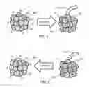
Referring to FIGS. 1 and 2, the absorption of hydrogen gas 11 into suitable metal alloy 202 leads to the exothermic formation of a metal hydride 204, producing useful heat as shown in FIG. 1 The endothermic desorption of hydrogen gas 11 is reversible, requiring about as much heat as that released by absorption, which thereby produces useful cooling, as shown in FIG. 2
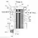
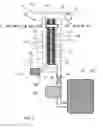
As shown in FIG. 3, an exemplary regenerative fuel cell system 100 comprises a regenerative fuel cell 101 that has a metal hydride 204 coupled with the membrane electrode assembly 13 in a hydrogen pumping mode. In a hydrogen pumping mode, water vapor, such as from the ambient air in introduced to the anode side 35, or source side 130, of the membrane electrode assembly. Any incoming air or gas stream may be filtered by a filter 110 and may be forced into an enclosure by an air moving device 150, such as a fan. The anode 30 having an electrical potential reacts with the water to produce to protons and electrons. The protons move across the proton conducting layer 31 that comprises an ionomer 34, to the cathode 32 on the cathode side 36, or storage side 140, of the membrane electrode assembly. The hydrogen is reformed on the cathode 32 and is absorbed by the metal alloy 202 to form metal hydride 204. In the hydrogen pumping mode, the membrane electrode assembly acts as an electrochemical compressor 12 for hydrogen, or a hydrogen pump 15, comprising a power source 28 and controller 90. The fluid or gas stream may enter into the system through a conduit 27 having an inlet 22 to the anode side. The equations of reaction are shown for the anode and cathode. Note that the metal hydride 204 may be spaced apart from, adjacent to, or attached to the cathode on the cathode side. A membrane electrode assembly may comprise a gas diffusion layer 37, 37′.
As shown in FIG. 4, the exemplary regenerative fuel cell system 100 shown in FIG. 3 is operating in a fuel cell mode, wherein power is being produced and being provided to a load 23. The hydrogen 11, from the metal hydride 204 is being reacted on the anode 30 to produce protons that pass through the proton conducting layer 31 to the cathode 32, wherein they are reacted with oxygen to produce water. The equations of the reactions on the anode and cathode are provided.
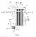
As shown in FIG. 5, an exemplary regenerative fuel cell system 100 comprises a regenerative fuel cell 101 having an integral metal hydride electrode 204 coupled with the membrane electrode assembly 13 in a hydrogen pumping mode. The integral metal hydride electrode comprises a metal hydride 204 or metal alloy 202, as described herein, and may comprise a catalyst 211 and/or ionomer 212. The metal hydride may be permeable or have pores to alloy coating of the catalyst and ionomer into a depth of the metal hydride. In an exemplary embodiment, the integral metal hydride electrode consists substantially of metal hydride and may have some ionomer penetrating into the depth of the integral metal hydride electrode. In a hydrogen pumping mode, water vapor, such as from the ambient air in introduced to the anode side 35, or source side 130, of the membrane electrode assembly. Any incoming air or gas stream may be filtered by a filter 110 and may be forced into an enclosure by an air moving device 150, such as a fan. The anode 30 having an electrical potential reacts with the water to produce to protons and electrons. The protons move across the proton conducting layer 31 that comprises an ionomer 34, to the cathode 32 on the cathode side 36, or storage side 140, of the membrane electrode assembly. The hydrogen is reformed on the cathode 32 and is absorbed by the metal alloy 202 to form metal hydride 204. In the hydrogen pumping mode, the membrane electrode assembly acts as an electrochemical compressor 12 for hydrogen, or a hydrogen pump 15, comprising a power source 28 and controller 90. The fluid or gas stream may enter into the system through a conduit 27 having an inlet 22 to the anode side. The equations of reaction are shown for the anode and cathode. Note that the metal hydride 204 may be spaced apart from, adjacent to, or attached to the cathode on the cathode side.
As shown in FIG. 6, the exemplary regenerative fuel cell system 100 shown in FIG. 5 is operating in a fuel cell mode, wherein power is being produced and being provided to a load 23. The hydrogen 11, from the integral metal hydride electrode 210 is being reacted on the anode 30 to produce protons that pass through the proton conducting layer 31 to the cathode 32, wherein they are reacted with oxygen to produce water. The equations of the reactions on the anode and cathode are provided.
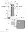
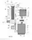
As shown in FIG. 7, an exemplary regenerative fuel cell system 100 comprises a regenerative fuel cell 101 operating in a hydrogen pumping mode wherein the hydrogen produced is pumped through an outlet 24 from the cathode side 36 and is stored in a reservoir 40. The reservoir may be a tank and may comprise hydride forming allow 43, or metal hydride 204. A valve 26 may control the flow of hydrogen to and from the reservoir. A compressor or pumping device 120 may increase the pressure of hydrogen in the reservoir. The membrane electrode assembly 13 may operate as a hydrogen pump 15 when operating in a hydrogen pumping mode and may pump hydrogen to an increased pressure within the reservoir.
As shown in FIG. 8, the exemplary regenerative fuel cell system 100 shown in FIG. 7 is operating in a fuel cell mode, wherein power is being produced and being provided to a load 23.
As shown in FIG. 9, an exemplary regenerative fuel cell system 10 comprises a regenerative fuel cell 101 that is supplying hydrogen to a first reservoir 40 having a metal hydride forming alloy 43. The first reservoir is coupled to a second reservoir 50 also containing a metal hydride forming alloy 43′. An electrochemical compressor 12′ and valves 26′, 26″ are configured between the two metal hydride reservoirs that act as heat transfer devices in an electrochemical heat transfer device 10. The first reservoir 40, or first heat transfer device 44, contains a first metal hydride forming alloy 42 that may be different or the same as the second metal hydride forming allow 52 in the second heat transfer device 54. A heat exchanger 47 may be coupled with the first heat transfer device 44 and a second heat exchanger 57 may be coupled with the second heat transfer device 54. As the electrochemical compressor 12′ pumps the hydrogen from one reservoir to the other, heat is produce in the reservoir receiving the hydrogen and heat is lost from the reservoir from which it is pumped.
As shown in FIG. 10, an exemplary regenerative fuel cell system 100 comprises a regenerative fuel cell 101 having an integral metal hydride electrode 210 that is an integral heat transfer device 220 that is coupled with the membrane electrode assembly 13 or regenerative fuel cell 101, and that is supplying hydrogen to a metal hydride heat transfer system having two reservoirs.
Certain exemplary embodiments of the present invention are described herein and are illustrated in the accompanying figures. The embodiments described are only for purposes of illustrating the present invention and should not be interpreted as limiting the scope of the invention. Other embodiments of the invention, and certain modifications, combinations, and improvements of the described embodiments, will occur to those skilled in the art and all such alternate embodiments, combinations, modifications, improvements are within the scope of the present invention.
Claims
1. A regenerative fuel cell system comprising:
a) a regenerative fuel cell comprising;
i) a membrane electrode assembly comprising:
a proton conducting layer comprising an ion conductive media;
an anode; and
a cathode;
wherein the proton conducting layer is configured between the anode and cathode;
b) a hydrogen storage reservoir coupled with a storage side of the membrane electrode assembly when the regenerative fuel cell operates in a hydrogen pumping mode;
c) a power supply that provides an electrical potential between the anode and cathode when operating in the hydrogen pumping mode;
wherein in said hydrogen pumping mode, water is reacted on the anode to produce protons that move across the proton conducting layer to the cathode where the protons are reacted to form pumped hydrogen that is stored in the hydrogen storage reservoir, and
wherein in said fuel cell mode, the pumped hydrogen is reacted on the anode said to produce protons that move across the proton conducting layer to the cathode where the protons are reacted with oxygen to form water.
2. A regenerative fuel of cell system of claim 1, wherein the hydrogen storage reservoir is coupled with the membrane electrode assembly.
3. A regenerative fuel of cell system of claim 1, wherein the hydrogen storage reservoir comprises a metal hydride forming alloy.
4. A regenerative fuel of cell system of claim 1, comprising an integral metal hydride electrode as the cathode when operating the in the hydrogen pumping mode and wherein the integral metal hydride electrode comprises a metal hydride forming alloy.
5. A regenerative fuel of cell system of claim 4, wherein the integral metal hydride electrode is attached to the proton conducting layer.
6. A regenerative fuel of cell system of claim 4, wherein the integral metal hydride electrode is attached to the proton conducting layer and wherein the ion conducting media penetrates into the integral metal hydride electrode.
7. A regenerative fuel of cell system of claim 4, wherein the integral metal hydride electrode comprises a catalyst.
8. A regenerative fuel of cell system of claim 7 wherein the catalyst is coated onto the metal hydride forming alloy.
9. A regenerative fuel of cell system of claim 1, comprising a compressor between the regenerative fuel cell and the hydrogen storage reservoir.
10. A regenerative fuel of cell system of claim 9, wherein the compressor is an electrochemical compressor comprising a membrane electrode assembly.
11. A regenerative fuel of cell system of claim 1, comprising a pump between the regenerative fuel cell and the hydrogen storage reservoir.
12. A regenerative fuel of cell system of claim 1, comprising a filter to filter incoming fluid to a source side of the membrane electrode assembly of the regenerative fuel cell.
13. A regenerative fuel of cell system of claim 1, comprising an air moving device force incoming fluid to a source side of the membrane electrode assembly of the regenerative fuel cell.
14. A regenerative fuel of cell system of claim 1, comprising gas diffusion media coupled with the anode.
15. A regenerative fuel of cell system of claim 1, comprising gas diffusion media coupled with the cathode.
16. A regenerative fuel of cell system of claim 1, further comprising an electrochemical heat transfer device.
17. A regenerative fuel of cell system of claim 16, comprising a heat exchanger coupled with the regenerative fuel cell.
18. A regenerative fuel of cell system of claim 16, wherein the electrochemical heat transfer device comprises a first reservoir comprising a metal hydride forming alloy that is coupled with and receives hydrogen from the regenerative fuel cell, and wherein heat is generated when hydrogen is pumped to the first reservoir and wherein heat is lost when hydrogen is pumped from the first reservoir.
19. A regenerative fuel of cell system of claim 18, wherein the hydrogen is pumped by the regenerative fuel cell to and from the first reservoir.
20. A regenerative fuel of cell system of claim 18, wherein the electrochemical heat transfer device comprises said first reservoir comprising a first metal hydride forming alloy and a second reservoir comprising a second metal hydride forming alloy and wherein the second reservoir is coupled with and receives hydrogen from the regenerative fuel cell wherein the hydrogen is pumped by the regenerative fuel cell to and from the first reservoir and second reservoirs.
21. A regenerative fuel of cell system of claim 20, further comprising an electrochemical compressor configured between the first and second reservoirs to pump hydrogen from the first reservoir to the second reservoir.
Images & Drawings included:


Sources:
- United States Patent and Trademark Office - verify current appl. status at the USPTO↗
Similar patent applications:
- » 20150118597
Metal separator for solid oxide regenerative fuel cell coated with conductive spinel oxide film, method for producing the same and solid oxide regenerative fuel cell including the same - » 20180198151
Method for operating of a regenerative bipolar membrane fuel cell, and regenerative bipolar membrane fuel cell there for - » 20050181244
REGENERATIVE FUEL CELL SYSTEM AND METHOD OF OPERATION THEREOF - » 10394203
Solid oxide regenerative fuel cell with selective anode tail gas circulation - » 10469578
Process for operating a regenerative fuel cell - » 10475139
Regenerative fuel cell with pH control - » 10299863
Solid oxide regenerative fuel cell for airplane power generation and storage - » 10891599
Unitized regenerative fuel cell system - » 12403783
Regenerative fuel cell and hydrogen storage system - » 13796158
Regenerative fuel cell and hydrogen storage system
Recent applications in this class:
- » 20240113319 2024-04-04
REVERSIBLE FUEL CELL AND ELECTROLYZER SYSTEM - » 20240014426 2024-01-11
VEHICLE - » 20230318002 2023-10-05
Hydrogen powered auxiliary power unit - » 20230178783 2023-06-08
Integrated solar hydrogen production module - » 20220393216 2022-12-08
ELECTROCHEMICAL CELL AND ELECTROCHEMICAL CELL STACK - » 20220359900 2022-11-10
HYBRID O2/H2 REGENERATIVE FUEL CELL SYSTEM - » 20220149415 2022-05-12
Systems and reactors for storage of electrical energy - » 20220109174 2022-04-07
Air electrodes of solid oxide electrochemical cells - » 20210066741 2021-03-04
High temperature-type unitized regenerative fuel cell using water vapor and method of operating the same - » 20200358123 2020-11-12
Passive flow battery
Recent applications for this Assignee:
- » 20200070142 2020-03-05
Multilayered ion exchange membranes - » 20190252707 2019-08-15
High pressure hydrogen electrical power generator - » 20190151796 2019-05-23
Carbon dioxide environmental control system - » 20190100844 2019-04-04
Environment control system utilizing an electrochemical cell - » 20180187906 2018-07-05
Cooling systems having an integrated ionic liquid salt dehumidification system - » 20180087794 2018-03-29
Environment control system utilizing an electrochemical cell - » 20170252707 2017-09-07
Anion exchange polymers and anion exchange membranes incorporating same - » 20170241677 2017-08-24
Furnishing temperature control system employing an electrochemical compressor - » 20170138653 2017-05-18
Electrochemical compressor refrigeration appartus with integral leak detection system - » 20170077528 2017-03-16
Bipolar plate for low pressure feed electrode operation