Antenna design for active load modulation in a near field communication transponder device
US20190036199A1
2019-01-31
15/662,440
2017-07-28
✅ Patent granted
US 10,505,254 B2
2019-12-10
-
-
Hai V Tran
Crowe & Dunlevy
2037-12-12
Abstract:
A near field communications (NFC) transponder includes a transmit circuit coupled to a transmit antenna and a receive circuit coupled to a receive antenna. The transmit/receive antennae are configured such that no signal is induced on the receive antenna by operation of the transmit antenna. Advantageously, this permits continued reception by the receive antenna while the transmit antenna is used for transmission using active load modulation.
Assignee:
- STMICROELECTRONICS, INC. 1,063 🇺🇸 Coppell, TX, United States
Applicant:
Interested in similar patents?
Get notified when new applications in this technology area are published.
Classification:
H01Q1/2225 » CPC main
Details of, or arrangements associated with, antennas; Supports; Mounting means by structural association with other equipment or articles associated with components used in interrogation type services, i.e. in systems for information exchange between an interrogator/reader and a tag/transponder, e.g. in Radio Frequency Identification [RFID] systems used in active tags, i.e. provided with its own power source or in passive tags, i.e. deriving power from RF signal
H01Q1/273 » CPC further
Details of, or arrangements associated with, antennas; Adaptation for use in or on movable bodies Adaptation for carrying or wearing by persons or animals
H01Q9/0478 » CPC further
Electrically-short antennas having dimensions not more than twice the operating wavelength and consisting of conductive active radiating elements; Resonant antennas; Substantially flat resonant element parallel to ground plane, e.g. patch antenna with means for suppressing spurious modes, e.g. cross polarisation
H01Q7/00 » CPC further
Loop antennas with a substantially uniform current distribution around the loop and having a directional radiation pattern in a plane perpendicular to the plane of the loop
H01Q1/22 IPC
Details of, or arrangements associated with, antennas; Supports; Mounting means by structural association with other equipment or articles
H04B5/0087 » CPC further
Near-field transmission systems, e.g. inductive loop type using inductive coupling with multiple coils at either side
H01Q1/27 IPC
Details of, or arrangements associated with, antennas Adaptation for use in or on movable bodies
H01Q9/04 IPC
Electrically-short antennas having dimensions not more than twice the operating wavelength and consisting of conductive active radiating elements Resonant antennas
G06K19/077 IPC
Record carriers for use with machines and with at least a part designed to carry digital markings characterised by the kind of the digital marking, e.g. shape, nature, code; Record carriers with conductive marks, printed circuits or semiconductor circuit elements, e.g. credit or identity cards also with resonating or responding marks without active components with integrated circuit chips Constructional details, e.g. mounting of circuits in the carrier
H04B5/00 IPC
Near-field transmission systems, e.g. inductive loop type
Description
TECHNICAL FIELD
The present invention relates to Near Field Communication (NFC) technologies and more particularly, to an antenna design for use in an NFC transponder device.
BACKGROUND
Near Field Communication (NFC) technologies enable contactless communications between devices. The number of applications, along with the corresponding market, for NFC systems grows on a daily basis. The conventional NFC system includes a reader terminal on one side of a contactless communications interface and a plurality of transponders on the other side of the contactless communications interface. An RF identification (RFID) tag is just one example of an NFC transponder device. In many cases, the transponder is a battery-less device that receives power over the contactless communications interface from the reader terminal. Data is communicated from the transponder to the reader terminal using well known passive load modulation (PLM) techniques. In passive load modulation, the transponder harvests some of the field power of the reader terminal and uses that power to modulate the amount of load that the reader terminal antenna senses.
Alternatively, an active transmission of data from the transponder to the reader terminal can be made through the use of active load modulation (ALM). To accomplish active load modulation, the transponder makes an RF transmission that is either in phase with or 180° out of phase with the field of the reader terminal. When the transponder field is in phase with the reader field, there is an increase in voltage at the reader antenna terminals that is sensed by the reader as the transmitted data. Conversely, when the transponder field is 180° out of phase with the reader field, there is a decrease in voltage at the reader antenna terminals that is sensed by the reader as the transmitted data.
In the past few years, a trend has emerged toward enabling NFC functionality on very small devices (such as wearables and mobile phones). The integration of NFC technology into such small devices necessitates the use of an antenna having a relatively speaking small occupied area or volume. As a result, passive load modulation is not feasible. Instead, active load modulation is needed. However, because the transponder antenna is smaller the transponder may not be able to harvest enough energy from the reader field. This is due to insufficient coupling between the transponder antenna and the reader antenna and further because the same antenna is being used in the transponder during transmission.
SUMMARY
In an embodiment, a near field communications (NFC) transponder comprises: a transmit circuit having a first output and a second output; a receive circuit having a first input and a second input; a transmit antenna having a first antenna segment coupled between the first and second outputs of the transmit circuit and a ground node and a second antenna segment coupled between the first and second outputs of the transmit circuit and the ground node; and a receive antenna having a first antenna terminal coupled to the first input of the receive circuit and a second antenna terminal coupled to the second input of the receive circuit; wherein the first antenna segment of the transmit antenna extends parallel to a first portion of the receive antenna and wherein the second antenna segment of the transmit antenna extends parallel to a second portion of the receive antenna.
In an embodiment, a near field communications (NFC) transponder comprises: a transmit circuit; a receive circuit having a first input and a second input; a transmit antenna electrically coupled to an output of the transmit circuit, the transmit antenna having a first antenna segment coupled between the output of the transmit circuit and a ground node and a second antenna segment coupled between the output of the transmit circuit and the ground node; and a receive antenna loop electrically coupled to an input of the receive circuit; wherein the first antenna segment of the transmit antenna extends parallel to a first portion of the receive antenna loop and wherein the second antenna segment of the transmit antenna extends parallel to a second portion of the receive antenna loop.
In an embodiment, a near field communications (NFC) transponder comprises: a transmit circuit having a first output and a second output; a receive circuit having a first input and a second input; a transmit antenna having a first antenna segment coupled in series with a second antenna segment between the first and second outputs of the transmit circuit; and a receive antenna having a first antenna terminal coupled to the first input of the receive circuit and a second antenna terminal coupled to the second input of the receive circuit; wherein the first antenna segment of the transmit antenna extends parallel to a first portion of the receive antenna and wherein the second antenna segment of the transmit antenna extends parallel to a second portion of the receive antenna.
BRIEF DESCRIPTION OF THE DRAWINGS
The accompanying drawings are included to provide a further understanding of the invention and are incorporated in and constitute a part of this specification, illustrate embodiments of the invention and together with the description serve to explain the principles of the invention.
In the drawings:
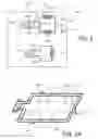
FIG. 1 shows a block diagram of a transponder having a dual antenna arrangement for use in Near Field Communication (NFC) applications;
FIGS. 2A-2B show examples for the physical arrangement of the transmit antenna and the receive antenna of FIG. 1;
FIGS. 3A-3C show use of a multi-turn antenna configuration for one or more of the transmit antenna and the receive antenna as shown in FIG. 2A;
FIG. 4 illustrates the relative size difference and magnetic relationship between the antennae of the transponder and the antenna of a reader terminal; and
FIGS. 5A-5B show examples for the physical arrangement of the transmit antenna and the receive antenna.
DETAILED DESCRIPTION
Reference is made to FIG. 1 which shows a block diagram of a transponder 100 having a dual antenna arrangement for use in Near Field Communication (NFC) applications. The transponder includes a transmit (TX) circuit 104 and a receive (RX) circuit 106. The transmit circuit 104 includes RF output terminals RFO1 and RFO2 directly electrically connected together by circuit 108 and directly electrically connected to a first end terminal of a first (segment) portion 110a of a transmit antenna 112 and directly electrically connected to a first end terminal of a second (segment) portion 110b of the transmit antenna 112. The second end terminals of the first and second (segments) portions 110a and 110b are directly electrically connected together by circuit 114 and further directly electrically connected to a ground node 116. The receive circuit 106 includes RF input terminals RFI1 and RFI2 connected to a corresponding first end terminal and second end terminal, respectively, of a receive antenna 118. The transponder 100 is contained within a portable electronic device 120 comprising, for example, a cellular (mobile) telephone or a human wearable device such as a watch or an exercise tracker.
In an implementation of the transmit circuit 104 where the RF output terminals RFO1 and RFO2 cannot be directly electrically connected together due to the transmit circuit electrical configuration, a balun 124 can instead be used with (balanced) inputs coupled to the RF output terminals RFO1 and RFO2 and a single-ended (unbalanced) output RFO to which the first end terminals of the first and second (segments) portions 110a and 110b of the transmit antenna 112 are directly electrically connected.
The impedances of the transmit antenna 112 and the receive antenna 118 are defined in accordance with the input and output impedance requirements of the terminals RFO1, RFO2, RFO, RFI1 and RFI2. Alternatively, a matching network will transfer the impedances of RFO1, RFO2, RFO, RFI1, and RFI2 to the impedance of the transmit antenna 112 and receive antenna 118.
FIG. 2A shows an embodiment for the physical arrangement of the transmit antenna 112 and the receive antenna 118. The transmit antenna 112 comprises at least a single turn of wire forming a loop between the terminals RFO1, RFO2 (or a loop connected to terminal RFO). The loop includes the first (segment) portion 110a and the second (segment) portion 110b, wherein the first (segment) portion 110a extends between the terminals RFO1, RFO2, RFO and ground node 116 and the second (segment) portion 110b extends between the terminals RFO1, RFO2, RFO and ground node 116 (and thus is electrically connected in parallel to the first (segment) portion 110a). The one or more turns of the transmit antenna 112 loop are arranged in a first plane. The receive antenna 118 also comprises at least a single turn of wire forming a loop between the terminals RFI1 and RFI2, and includes a first portion 111a extending parallel to the first (segment) portion 110a and a second portion 111b extending parallel to the second (segment) portion 110b. The one or more turns of the receive antenna 118 loop are arranged in a second plane. In an embodiment, the first and second planes are parallel to each other. In a more particular implementation, the first and second planes are coplanar (i.e., they are in the same plane). In a preferred implementation with the antennae planes either parallel or coplanar as shown in FIG. 2A, the transmit antenna 112 loop surrounds the receive antenna 118 loop.
In an alternative implementation, as shown in FIG. 2B, the first and second planes may be perpendicular to each other, in which case the ground node 116 connection of the transmit antenna 112 is not needed and transmit antenna segments 110a, 110b can be individually connected to RFO1 and RFO2, respectively. The connection 108 is not needed in this implementation.
Although FIGS. 2A and 2B illustrate a particular implementation where only single turn antennae loops are used, it will be understood that this is just one example. In an embodiment as shown in FIG. 3A, the transmit antenna 112 comprises a single turn antenna loop and the receive antenna 118 is a multi-turn (for example, spiral winding) antenna loop. The implementation of FIG. 3B shows the transmit antenna 112 as a multi-turn antenna (for example, spiral winding) loop and the receive antenna 118 as a single turn antenna loop. The implementation of FIG. 3C shows the transmit antenna 112 as a multi-turn (for example, spiral winding) antenna loop and the receive antenna 118 as a multi-turn (for example, spiral winding) antenna loop. The implementations using one or more multi-turn (for example, spiral winding) antenna loops are equally applicable for use in connection with the perpendicular plane configuration of FIG. 2B.
The arrows 140 show the direction of current flow in the first portion 110a and the second portion 110b of the transmit antenna 112. This current flow produces magnetic field lines 142a and 142b, respectively, which cancel each other and thus do not induce a signal on the receive antenna 118. Because no signal is induced by the transmit antenna 112 on the receive antenna 118 due to current flow in the transmit antenna 112, the receive circuit 106 can continuously monitor the reader terminal field during transmit circuit 104 operation and thus function to receive signals from the reader terminal and maintain synchronization with the reader terminal without interruption.
As previously noted, the integration of NFC functionality on very small devices (such as wearables and mobile phones) necessitates the use of small antennae for the transmit antenna 112 and the receive antenna 118. Indeed, FIG. 4 provides a general indication of the relative size difference between the transmit antenna 112 and the receive antenna 118 in comparison to reader terminal antenna 150. It will be understood that FIG. 4 does not necessarily show a scale size relationship, but rather illustrates the relative size relationship where the planar area occupied by the transmit antenna 112 and the receive antenna 118 in the transponder 100 is much smaller than the planar area occupied by the reader terminal antenna 150. At this level, the current flow in the first portion 110a and the second portion 110b of the transmit antenna 112 produces magnetic field lines 144a and 144b, respectively, which add to each other so as to induce a signal on the reader terminal antenna 150.
Because a passive linear system is used, the positions of the antennae shown in FIG. 1 can be exchanged.
FIG. 5A shows an embodiment for the physical arrangement of the transmit antenna 112′ and the receive antenna 118′ where the antenna positions have been exchanged in comparison to FIG. 2A. In an alternative implementation, as shown in FIG. 5B, the first and second planes may be perpendicular to each other (compare to FIG. 2B).
In a preferred implementation with the antennae planes either parallel or coplanar as shown in FIG. 5A, the receive antenna 118′ loop surrounds the transmit antenna 112′ loop. In a manner analogous to that shown and described herein with respect to FIG. 2A, the antennae configuration of FIG. 5A supports magnetic field lines 142′a and 142′b for the transmit antenna 112′ that do not induce a signal on the receive antenna 118′. Because no signal is induced by the transmit antenna 112′ on the receive antenna 118′, the receive circuit 106 can continuously monitor the reader terminal field during transmit circuit 104 operation and thus function to receive signals from the reader terminal and maintain synchronization with the reader terminal without interruption.
Although FIGS. 5A-5B illustrate a particular implementation where only single turn antennae loops are used, it will be understood that this is just one example. As noted herein with respect to FIGS. 3A-3C, one or the other or both of the included antennae could be implemented as a multi-turn (for example, spiral winding) antenna loop.
The relative size relationship between the antennae of the transponder and the antenna of the reader as shown in FIG. 4 is equally applicable to the implementation of FIGS. 5A and 5B.
It will be apparent to those skilled in the art that various modifications and variations can be made in the present invention without departing from the spirit or scope of the invention. Thus, it is intended that the present invention cover the modifications and variations of this invention provided they come within the scope of the appended claims and their equivalents.
Claims
1. A near field communications (NFC) transponder, comprising:
a transmit circuit having a first output and a second output;
a receive circuit having a first input and a second input;
a transmit antenna having a first antenna segment coupled between the first and second outputs of the transmit circuit and a ground node and a second antenna segment coupled between the first and second outputs of the transmit circuit and the ground node; and
a receive antenna having a first antenna terminal coupled to the first input of the receive circuit and a second antenna terminal coupled to the second input of the receive circuit;
wherein the first antenna segment of the transmit antenna extends parallel to a first portion of the receive antenna and wherein the second antenna segment of the transmit antenna extends parallel to a second portion of the receive antenna.
2. The NFC transponder of claim 1, wherein the first and second antenna segments for the transmit antenna are formed in a first plane and wherein the receive antenna is formed in a second plane.
3. The NFC transponder of claim 2, wherein the first and second planes are parallel planes.
4. The NFC transponder of claim 2, wherein the first and second planes are coplanar planes.
5. The NFC transponder of claim 1, wherein the first and second outputs of the transmit circuit are directly electrically connected to each other and directly electrically connected to a first antenna terminal of each of the first and second antenna segments.
6. The NFC transponder of claim 1, wherein a second antenna terminal of each of the first and second antenna segments is directly electrically connected to the ground node.
7. The NFC transponder of claim 1, wherein the first and second outputs of the transmit circuit are directly electrically connected to balanced inputs of a balun and an unbalanced output of the balun is directly electrically connected to a first antenna terminal of each of the first and second antenna segments.
8. The NFC transponder of claim 7, wherein a second antenna terminal of each of the first and second antenna segments is directly electrically connected to the ground node.
9. The NFC transponder of claim 1, wherein the transmit antenna is formed in a loop that completely surrounds the receive antenna.
10. The NFC transponder of claim 1, wherein the receive antenna is formed in a loop that completely surrounds the transmit antenna.
11. A near field communications (NFC) transponder, comprising:
a transmit circuit;
a receive circuit having a first input and a second input;
a transmit antenna electrically coupled to an output of the transmit circuit, the transmit antenna having a first antenna segment coupled between the output of the transmit circuit and a ground node and a second antenna segment coupled between the output of the transmit circuit and the ground node; and
a receive antenna loop electrically coupled to an input of the receive circuit;
wherein the first antenna segment of the transmit antenna extends parallel to a first portion of the receive antenna loop and wherein the second antenna segment of the transmit antenna extends parallel to a second portion of the receive antenna loop.
12. The NFC transponder of claim 11, wherein the first and second antenna segments for the transmit antenna are formed in a first plane and wherein the receive antenna loop is formed in a second plane.
13. The NFC transponder of claim 12, wherein the first and second planes are parallel planes.
14. The NFC transponder of claim 12, wherein the first and second planes are coplanar planes.
15. The NFC transponder of claim 11, further including a balun coupled between the output of the transmit circuit and the transmit antenna.
16. The NFC transponder of claim 11, wherein the transmit antenna is formed in a loop that completely surrounds the receive antenna loop.
17. The NFC transponder of claim 11, wherein the receive antenna loop completely surrounds the transmit antenna.
18. A near field communications (NFC) transponder, comprising:
a transmit circuit having a first output and a second output;
a receive circuit having a first input and a second input;
a transmit antenna having a first antenna segment coupled in series with a second antenna segment between the first and second outputs of the transmit circuit; and
a receive antenna having a first antenna terminal coupled to the first input of the receive circuit and a second antenna terminal coupled to the second input of the receive circuit;
wherein the first antenna segment of the transmit antenna extends parallel to a first portion of the receive antenna and wherein the second antenna segment of the transmit antenna extends parallel to a second portion of the receive antenna.
19. The NFC transponder of claim 18,
wherein the first and second antenna segments for the transmit antenna are formed in a first plane and wherein the receive antenna is formed in a second plane, and
wherein the first and second planes are perpendicular planes.
Images & Drawings included:


Sources:
- United States Patent and Trademark Office - verify current appl. status at the USPTO↗
Recent applications in this class:
- » 20250167425 2025-05-22
SURGICAL SPONGES WITH FLEXIBLE RFID TAGS - » 20250141087 2025-05-01
ANTENNA INLAY FOR A DOCUMENT AND DOCUMENT WITH SUCH AN ANTENNA INLAY - » 20250038395 2025-01-30
RFID Antenna - » 20240235005 2024-07-11
SURGICAL SPONGES WITH FLEXIBLE RFID TAGS - » 20240136700 2024-04-25
Surgical sponges with flexible RFID tags - » 20240097310 2024-03-21
WIRELESS SENSOR WITH EXTENDED POWER FOR USE WITH SPACECRAFT - » 20240039140 2024-02-01
Modular Antenna for an RFID Reading Device - » 20240014542 2024-01-11
WIRELESS PASSIVE ELECTRONIC COMPONENT AND ASSOCIATED READING SYSTEM - » 20230395966 2023-12-07
RFID TAG AND MANUFACTURING METHOD THEREOF - » 20230335881 2023-10-19
MOUNTING MEMBER WITH RFID TAG, MANUFACTURING METHOD FOR MOUNTING MEMBER WITH RFID TAG, HEAD UNIT OF MOUNTING MEMBER WITH RFID TAG, AND RFID TAG MOUNT UNIT
Recent applications for this Assignee:
- » 20250264332 2025-08-21
MEMS GYROSCOPE START-UP PROCESS AND CIRCUIT - » 20250169120 2025-05-22
HIGH DOSE IMPLANTATION FOR ULTRATHIN SEMICONDUCTOR-ON-INSULATOR SUBSTRATES - » 20250151395 2025-05-08
INTEGRATED CIRCUIT DEVICES AND FABRICATION TECHNIQUES - » 20250126850 2025-04-17
STRAINED-CHANNEL FIN FETS - » 20240244406 2024-07-18
DEVICE, SYSTEM AND METHOD FOR SYNCHRONIZING OF DATA FROM MULTIPLE SENSORS - » 20240192762 2024-06-13
Sensor unit with on-device unsupervised learning and classification - » 20240188837 2024-06-13
CUFFLESS BLOOD PRESSURE MONITOR WITH MULTIPLE INERTIAL MEASUREMENT UNITS - » 20240145480 2024-05-02
Integrated circuit devices and fabrication techniques - » 20240067184 2024-02-29
METHOD FOR MOTION ESTIMATION IN A VEHICLE, CORRESPONDING DEVICE AND COMPUTER PROGRAM PRODUCT - » 20240045001 2024-02-08
SYSTEM AND METHOD FOR FAST MAGNETOMETER CALIBRATION USING GYROSCOPE