Item Storage Bag
US20190174891A1
2019-06-13
16/218,406
2018-12-12
Abstract:
A bag with pockets is an apparatus used to store items for later usage. The apparatus is configured to contain smaller items separately from larger items, thus facilitating location and subsequent removal of smaller items. The apparatus includes a main receptacle, a first pocket, and a main closure. The main receptacle is the larger space into which the user may place larger items. The first pocket is a smaller space proximal to the main receptacle that allows for storage of smaller items separately from larger items. The main closure is a fastener that secures the main receptacle and the first pocket in the closed position, thus preventing items from exiting the apparatus accidentally. This arrangement ensures that the user has convenient space for items of all sizes. The user no longer has to search for small items at the bottom of a bag amidst larger items.
Interested in similar patents?
Get notified when new applications in this technology area are published.
Classification:
A45C3/001 » CPC further
Flexible luggage; Handbags Flexible materials therefor
A45C3/06 » CPC main
Flexible luggage; Handbags Ladies' handbags
A45C13/02 » CPC further
Details; Accessories Interior fittings; Means, e.g. inserts, for holding and packing articles
Description
The current application claims a priority to the U.S. Provisional Patent application Ser. No. 62/597,531 filed on Dec. 12, 2017.
FIELD OF THE INVENTION
The present invention generally relates to portable receptacles. More specifically, present invention relates to a device with flexible openings that contain various items a user might need. The present invention has a shallow side pocket located towards the main opening of the bag for smaller items that prevents these smaller items from mixing and getting lost among larger items.
BACKGROUND OF THE INVENTION
On any given day, a person has several items that must be on hand, in addition to items that are useful to have available. Phones, wallets, and keys are crucial items, while other items such as clothing options, laptops, electrical chargers, cosmetic tools and devices, umbrellas, and other items depending on conditions such as weather, temperature, and the requirements of the day. To this end, a wide variety of bags have been created. Several such bags typically have a large pocket for containing items, and a strap for carrying over the shoulder of the user. These bags also typically have patterns or decorations that a user can match with their outfit for the day.
However, such bags typically have several restrictions limiting their effectiveness. The use of one large bag means that smaller items typically fall to the bottom of the bag, making them inaccessible. These smaller items, such as lip balms, pencils, pens, and headphones, are difficult to identify and grasp amongst the internal clutter. In order to locate those items, bag users have to dig their hands into the bag past their larger items. In any ordinary bag, the user must at times empty the entire contents of their bag, simply to find a small item that is unseen; therefore, the small item is unattainable without going through the process of inconveniently remove existing contents. This is not only a consistently time-consuming annoyance, but also a safety concern as the users private and valuable items are removed and perhaps placed on another surface which is susceptible to being lost, stolen, or misplaced. This often results in the user removing the wrong items from the bag and the user consequently having to continue digging for items. What is needed is a device that can store small items separately from larger items, for ease of item removal. Further needed is a bag that provides the user with elevated pockets that improve the ability of a user to locate, remove, and store smaller items.
The present invention addresses these issues. The present invention is a bag-like receptacle with various designs and a strap that enables the user to carry the present invention between locations, thus enabling the user to transport items from location to location. Pockets are located at the top of the inside of the main opening, as well as outside of the main bag opening, enabling the user to store items conveniently for subsequent usage. The present invention may be made of a variety of materials and may also utilize a variety of designs, thus enabling users to coordinate their bags with their clothing. The present invention may utilize closures including kiss-locks, zippers, and other closure means. The present invention can further be carried as either a traditional arm or shoulder bag, or as a backpack.
BRIEF DESCRIPTION OF THE DRAWINGS
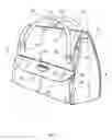
FIG. 1 is a front-right perspective view of the present invention.
FIG. 2 is a front-left perspective view of the present invention.
FIG. 3 is a back perspective view of the present invention.
FIG. 4 is a right perspective view of the present invention.
FIG. 5 is a schematic view of a left cross-section of the present invention.
DETAILED DESCRIPTION OF THE INVENTION
All illustrations of the drawings are for the purpose of describing selected versions of the present invention and are not intended to limit the scope of the present invention.
The present invention is a bag with pockets that is used to store items for later usage. The present invention is configured to contain smaller items separately from larger items, thus facilitating location and subsequent removal of smaller items. The present invention comprises a main receptacle 1, a first pocket 10, and a main closure 13, as seen in FIG. 1. The main receptacle 1 is the larger space into which the user may place larger items. The first pocket 10 is a smaller space proximal to the main receptacle 1 that allows for storage of smaller items separately from larger items. The main closure 13 is a fastener that secures the main receptacle 1 and the first pocket 10 in the closed position, thus preventing items from exiting the present invention by accident. The main receptacle 1 comprises a receptacle rim 2 and a receptacle base 3. The receptacle rim 2 is the section of the main receptacle 1 that wraps around the upper portion of the main receptacle 1. The receptacle base 3 is the section of the main receptacle 1 that supports the present invention when the present invention is placed upon the ground. The first pocket 10 comprises a pocket rim 11 and a pocket base 12. The pocket rim 11 is the section of the pocket that allows for input and removal of items. The pocket base 12 is the portion of the first pocket 10 that supports items within the first pocket 10. The main closure 13 comprises a first main interlocking piece 14 and a second main interlocking piece 15. The first main interlocking piece 14 is a connector that works in conjunction with the second main interlocking piece 15 to enable the main closure 13 to close both the main receptacle 1 and the first pocket 10.
The general configuration of the aforementioned components allows the present invention to efficiently and effectively store items for later usage. The first pocket 10 is laterally connected to the main receptacle 1, as seen in FIG. 2. Furthermore, the pocket rim 11 is positioned adjacent to the receptacle rim 2. This arrangement allows for the user to separate items into the proper pockets with improved ease. The pocket base 12 is positioned offset from the receptacle base 3. In this way, items placed within the first pocket 10 are situated above items placed within the main receptacle 1. The first main interlocking piece 14 is connected about the receptacle rim 2, opposite the first pocket 10. Moreover, the second main interlocking piece 15 is connected about the pocket rim 11, opposite the main receptacle 1. The arrangement of the first main interlocking piece 14 and the second main interlocking piece 15 results in the main closure 13 toggling the corresponding openings of the main receptacle 1 and the first pocket 10 between an open position and a closed position.
In an exemplary embodiment, the first main interlocking piece 14 and the second main interlocking piece 15 are components which allow the user to easily and conveniently open and close the present invention. To this end, the first main interlocking piece 14 is a first kiss-locking bracket. Similarly, the second main interlocking piece 15 is a second kiss-locking bracket. Consequently, spherical portions of the first kiss-locking bracket and the second kiss-locking bracket extend from the receptacle rim 2 and the pocket rim 11 and enable the user to close the present invention using friction between the first main interlocking piece 14 and the second main interlocking piece 15, as seen in FIGS. 1 and 3. In this way, the first main interlocking piece 14 and the second main interlocking piece 15 are able to join to secure the present invention in the closed position. The first kiss-locking bracket and the second kiss-locking bracket are hingedly connected to each other. This arrangement allows the first main interlocking piece 14 and the second main interlocking piece 15 to connect when the user pinches the first main interlocking piece 14 and the second main interlocking piece 15 together. This arrangement also allows the first main interlocking piece 14 and second main interlocking piece 15 to be easily pried apart in order to remove contained items from either the main receptacle 1 or the first pocket 10. In an alternative embodiment, the first main interlocking piece 14 and the second main interlocking piece 15 are opposing segments of a zipper-controlled closure.
The present invention requires a fair amount of internal space for storage of items. To this end, the main receptacle 1 comprises a first widthwise panel 4, a second widthwise panel 5, a first lengthwise panel 6, and a second lengthwise panel 7. The first widthwise panel 4 and the second widthwise panel 5 are two generally parallel sides of the main receptacle 1 that define the width of the main receptacle 1, as seen in FIG. 4.
The first lengthwise panel 6 and the second lengthwise panel 7 are two generally parallel sides of the main receptacle 1 that define the length of the main receptacle 1. The first lengthwise panel 6 and the second lengthwise panel 7 are positioned opposite each other about the main receptacle 1. In addition, the first widthwise panel 4 and the second widthwise panel 5 are positioned opposite each other about the main receptacle 1. This arrangement ensures that the first widthwise panel 4, second widthwise panel 5, first lengthwise panel 6, and second lengthwise panel 7 define the volume contained by the main receptacle 1. The first widthwise panel 4 and the second widthwise panel 5 are positioned in between the first lengthwise panel 6 and the second lengthwise panel 7. This arrangement fully encloses the volume defined by the main receptacle 1. In an exemplary embodiment, the first pocket 10 traverses from the first widthwise panel 4 to the second widthwise panel 5. This arrangement ensures that the first pocket 10 has an identical width to the main receptacle 1, which optimizes the containment volume for the first pocket 10. In another embodiment, the first pocket 10 is connected adjacent to the first lengthwise panel 6 which allows the receptacle rim 2 to delineate the largest possible continuous opening for the main receptacle 1. In this way, the first pocket 10 is positioned away from the second lengthwise panel 7.
The user further benefits from the ability to place the present invention upon the ground without slippage. To this end, the present invention further comprises a plurality of gripping nubs 16, as seen in FIG. 2. The plurality of gripping nubs 16 is a set of high-friction rubberized extrusions that prevent the present invention from sliding on the ground. The plurality of gripping nubs 16 is externally connected to the receptacle base 3. This arrangement allows the plurality of gripping nubs 16 to contact various surfaces. The plurality of gripping nubs 16 is distributed across the receptacle base 3. In this way, the plurality of gripping nubs 16 is adequately dispersed to keep the other components of the present invention from contacting the ground. The plurality of gripping nubs 16 is oriented away from the receptacle rim 2. This arrangement ensures that the main receptacle 1 is elevated off of the ground.
Many users may have a large number of items to contain and may therefore require volume not available from the main receptacle 1 and the first pocket 10. To this end, the present invention comprises at least one second pocket 17 and at least one second fastener 19, as seen in FIG. 1. The at least one second pocket 17 relates to a set of openings distributed upon the present invention for extra storage. The at least one second fastener 19 relates to a set of closures that cover the at least one second pocket 17. The at least one second pocket 17 is laterally connected to the main receptacle 1. In this way, the at least one second pocket 17 provides extra space for items near the main receptacle 1. The at least one second pocket 17 is positioned adjacent to the receptacle base 3. In this way, the at least one second pocket 17 provides space for items away from the first pocket 10. The at least one second fastener 19 mounted adjacent to the at least one second pocket 17. This arrangement allows the at least one second fastener 19 to cover the at least one second pocket 17.
The at least one second fastener 19 prevents objects from falling out of or otherwise unintentionally entering of exiting the at least one second pocket 17. In an exemplary embodiment, the at least one second fastener 19 comprises a flap 20 and a clasp 23, as seen in FIG. 1. The flap 20 is a cover that protects the openings of the pockets. The clasp 23 is a fastener that prevents the flap 20 from lifting unexpectedly from its resting position. The flap 20 comprises a fixed edge 21 and a free edge 22. The fixed edge 21 secures to the present invention to ensure proper coverage of the at least one second pocket 17. The free edge 22 is the segment of the flap 20 that lifts and falls to readily open or close the at least one second pocket 17. The fixed edge 21 and the free edge 22 are positioned opposite to each other across the flap 20. In this way, the flap 20 is able to lift and fall about a fixed position on the present invention. The fixed edge 21 is hingedly connected to the main receptacle 1, adjacent to an opening 18 of the at least one second pocket 17. This arrangement allows the free edge 22 to fold over a respective pocket of the at least one second pocket 17. The clasp 23 is integrated into the at least one second pocket 17, adjacent to the opening 18 of the at least one second pocket 17.
Further, the fixed edge 21 and the clasp 23 are positioned opposite to each other about the opening 18 of the at least one second pocket 17. In this way, the clasp 23 is appropriately positioned to secure the flap 20 across the opening 18 of the at least one second pocket 17. The at least one second pocket 17 is positioned adjacent to the first pocket 10. This arrangement provides convenient supplemental pocket storage proximal to the first pocket 10.
The user may desire a bag that retains its general shape, as opposed to a bag that conforms to the shape of the items within. To this end, the main receptacle 1 comprises a receptacle lateral wall 8 and at least one semirigid structural layer 9, as seen in FIG. 5. The receptacle lateral wall 8 is the sidewall extending from around the receptacle base 3 to the receptacle rim 2. The at least one semirigid structural layer 9 is a support that provides structure for the present invention. The at least one semirigid structural layer 9 is integrated through the receptacle base 3 and the receptacle lateral wall 8. This arrangement allows the at least one semirigid structural layer 9 to support items within the receptacle without compromising the integrity of the at least one semirigid structural layer 9.
The user may further desire to wear the present invention over a shoulder, an arm, or upon both shoulders at once. To this end, the present invention comprises at least one strap 24. The at least one strap 24 relates to a flexible band that enables the user to conveniently carry the present invention when any or any combination of the main receptacle 1, the first pocket 10, and the at least one second pocket 17 are full of items. The at least one strap 24 comprises a first strap end 25 and a second strap end 26, as seen in FIG. 2. The first strap end 25 is a section of the at least one strap 24 opposite the second strap end 26. The first strap end 25 is laterally connected to the main receptacle 1, adjacent to the receptacle rim 2. Similarly, the second strap end 26 is laterally connected to the main receptacle 1, adjacent to the receptacle rim 2. In this way, the first strap end 25 and the second strap end 26 allow for adjustable connection of the at least one strap 24 to the main receptacle 1. The first strap end 25 and the second strap end 26 are positioned offset from each other. This arrangement ensures adequate application and dispersal of forces upon the main receptacle 1.
Although the invention has been explained in relation to its preferred embodiment, it is to be understood that many other possible modifications and variations can be made without departing from the spirit and scope of the invention as hereinafter claimed.
Claims
What is claimed is:1. An item storage bag comprises:
a main receptacle;
a first pocket;
a main closure;
the main receptacle comprises a receptacle rim and a receptacle base;
the first pocket comprises a pocket rim and a pocket base;
the main closure comprises a first main interlocking piece and a second main interlocking piece;
the first pocket being laterally connected to the main receptacle;
the pocket rim being positioned adjacent to the receptacle rim;
the pocket base being positioned offset from the receptacle base;
the first main interlocking piece being connected about the receptacle rim, opposite the first pocket; and
the second main interlocking piece being connected about the pocket rim, opposite the main receptacle.
2. The item storage bag as claimed in claim 1 comprises:
the first main interlocking piece being a first kiss-locking bracket;
the second main interlocking piece being a second kiss-locking bracket; and
the first kiss-locking bracket and the second kiss-locking bracket being hingedly connected to each other.
3. The item storage bag as claimed in claim 1 comprises:
the main receptacle comprises a first widthwise panel, a second widthwise panel, a first lengthwise panel, and a second lengthwise panel;
the first lengthwise panel and the second lengthwise panel being positioned opposite each other about the main receptacle;
the first widthwise panel and the second widthwise panel being positioned opposite each other about the main receptacle; and
the first widthwise panel and the second widthwise panel being positioned in between the first lengthwise panel and the second lengthwise panel.
4. The item storage bag as claimed in claim 3 comprises:
the first pocket traversing from the first widthwise panel to the second widthwise panel.
5. The item storage bag as claimed in claim 3 comprises:
the first pocket being connected adjacent to the first lengthwise panel.
6. The item storage bag as claimed in claim 1 comprises:
a plurality of gripping nubs;
the plurality of gripping nubs being externally connected to the receptacle base;
the plurality of gripping nubs being distributed across the receptacle base; and
the plurality of gripping nubs being oriented away from the receptacle rim.
7. The item storage bag as claimed in claim 1 comprises:
at least one second pocket;
at least one second fastener;
the at least one second pocket being laterally connected to the main receptacle;
the at least one second pocket being positioned adjacent to the receptacle base; and
the at least one second fastener being mounted adjacent to the at least one second pocket.
8. The item storage bag as claimed in claim 7 comprises:
the at least one second fastener comprises a flap and a clasp;
the flap comprises a fixed edge and a free edge;
the fixed edge and the free edge being positioned opposite to each other across the flap;
the fixed edge being hingedly connected to the main receptacle, adjacent to an opening of the at least one second pocket;
the clasp being integrated into the at least one second pocket, adjacent to the opening of the at least one second pocket; and
the fixed edge and the clasp being positioned opposite to each other about the opening of the at least one second pocket.
9. The item storage bag as claimed in claim 7 comprises:
the at least one second pocket being positioned adjacent to the first pocket.
10. The item storage bag as claimed in claim 1 comprises:
the main receptacle comprises a receptacle lateral wall and at least one semirigid structural layer; and
the at least one semirigid structural layer being integrated through the receptacle base and the receptacle lateral wall.
11. The item storage bag as claimed in claim 1 comprises:
at least one strap;
the at least one strap comprises a first strap end and a second strap end;
the first strap end being laterally connected to the main receptacle, adjacent to the receptacle rim;
the second strap end being laterally connected to the main receptacle, adjacent to the receptacle rim; and
the first strap end and the second strap end being positioned offset from each other.
12. An item storage bag comprises:
a main receptacle;
a first pocket;
a main closure;
at least one second pocket;
at least one second fastener;
at least one strap;
the main receptacle comprises a receptacle rim and a receptacle base;
the first pocket comprises a pocket rim and a pocket base;
the main closure comprises a first main interlocking piece and a second main interlocking piece;
the at least one strap comprises a first strap end and a second strap end;
the first pocket being laterally connected to the main receptacle;
the pocket rim being positioned adjacent to the receptacle rim;
the pocket base being positioned offset from the receptacle base;
the first main interlocking piece being connected about the receptacle rim, opposite the pocket;
the second main interlocking piece being connected about the pocket rim, opposite the main receptacle;
the at least one second pocket being laterally connected to the main receptacle;
the at least one second pocket being positioned adjacent to the receptacle base;
the at least one second fastener being mounted adjacent to the at least one second pocket;
the first strap end being laterally connected to the main receptacle, adjacent to the receptacle rim;
the second strap end being laterally connected to the main receptacle, adjacent to the receptacle rim; and
the first strap end and the second strap end being positioned offset from each other.
13. The item storage bag as claimed in claim 11 comprises:
the first main interlocking piece being a first kiss-locking bracket;
the second main interlocking piece being a second kiss-locking bracket; and
the first kiss-locking bracket and the second kiss-locking bracket being hingedly connected to each other.
14. The item storage bag as claimed in claim 11 comprises:
the main receptacle comprises a first widthwise panel, a second widthwise panel, a first lengthwise panel, and a second lengthwise panel;
the first lengthwise panel and the second lengthwise panel being positioned opposite each other about the main receptacle;
the first widthwise panel and the second widthwise panel being positioned opposite each other about the main receptacle; and
the first widthwise panel and the second widthwise panel being positioned in between the first lengthwise panel and the second lengthwise panel.
15. The item storage bag as claimed in claim 13 comprises:
the first pocket traversing from the first widthwise panel to the second widthwise panel.
16. The item storage bag as claimed in claim 13 comprises:
the first pocket being connected adjacent to the first lengthwise panel.
17. The item storage bag as claimed in claim 11 comprises:
a plurality of gripping nubs;
the plurality of gripping nubs being externally connected to the receptacle base;
the plurality of gripping nubs being distributed across the receptacle base; and
the plurality of gripping nubs being oriented away from the receptacle rim.
18. The item storage bag as claimed in claim 11 comprises:
the at least one second fastener comprises a flap and a clasp;
the flap comprises a fixed edge and a free edge;
the fixed edge and the free edge being positioned opposite to each other across the flap;
the fixed edge being hingedly connected to the main receptacle, adjacent to an opening of the at least one second pocket;
the clasp being integrated into the at least one second pocket, adjacent to the opening of the at least one second pocket; and
the fixed edge and the clasp being positioned opposite to each other about the opening of the at least one second pocket.
19. The item storage bag as claimed in claim 11 comprises:
the at least one second pocket being positioned adjacent to the first pocket.
20. The item storage bag as claimed in claim 11 comprises:
the main receptacle comprises a receptacle lateral wall and at least one semirigid structural layer; and
the at least one semirigid structural layer being integrated through the receptacle base and the receptacle lateral wall.
Images & Drawings included:


Sources:
- United States Patent and Trademark Office - verify current appl. status at the USPTO↗
Similar patent applications:
- » 20190367220
Storage tray bag for prepared food item and method of use - » 20110056855
PLASTIC STORAGE BAGS FOR MOVING CLOTHING OR OTHER ITEMS WITH HANGER IN PLACE - » 20220287428
Item of luggage provided with a vacuum storage bag - » 20190366901
Convertible storage tray and garbage bag holder and method of using the same to collect garbage or hold an item
Recent applications in this class:
- » 20250082075 2025-03-13
UTILITY HANDBAG - » 20240023683 2024-01-25
Partitioned Handbag - » 20230232949 2023-07-27
Multifunctional Bag - » 20230165346 2023-06-01
User reconfigurable handbags - » 20230114097 2023-04-13
Travel accessory - » 20220378159 2022-12-01
Handmade handbag - » 20210085043 2021-03-25
Handbag with detachable and interchangeable facets - » 20210059367 2021-03-04
Dual-Compartment Handbag - » 20200170361 2020-06-04
HANDBAGS - » 20190328092 2019-10-31
Reversible and expandable handbag