Power-off braking system
US20190249732A1
2019-08-15
16/335,030
2017-09-14
✅ Patent granted
US 10,989,261 B2
2021-04-27
WO; PCT/FR2017/000167; 20170914
WO; WO2018/055243; 20180329
Thomas J Williams
Volpe Koenig
2037-09-14
Abstract:
A power-off emergency braking system, or parking brake system is presented in which, at each power-up, energy is stored in the structure of the brake so as to ensure the power-off application of the brake and the holding of same in the event of an interruption to the power supply of the device.
Applicant:
Interested in similar patents?
Get notified when new applications in this technology area are published.
Classification:
B60T13/04 » CPC further
Transmitting braking action from initiating means to ultimate brake actuator with power assistance or drive; Brake systems incorporating such transmitting means, e.g. air-pressure brake systems with mechanical assistance or drive by spring or weight
F16D55/225 » CPC further
Brakes with substantially-radial braking surfaces pressed together in axial direction, e.g. disc brakes with axially-movable discs or pads pressed against axially-located rotating members by clamping an axially-located rotating disc between movable braking members, e.g. movable brake discs or brake pads with a common actuating member for the braking members the braking members being brake pads
B60T7/12 » CPC further
Brake-action initiating means for automatic initiation; for initiation not subject to will of driver or passenger
F16D65/18 » CPC main
Parts or details; Actuating mechanisms for brakes; Means for initiating operation at a predetermined position arranged in or on the brake adapted for drawing members together, e.g. for disc brakes
F16D2121/14 » CPC further
Type of actuator operation force Mechanical
B60T1/10 » CPC further
Arrangements of braking elements, i.e. of those parts where braking effect occurs specially for vehicles acting by retarding wheels by utilising wheel movement for accumulating energy, e.g. driving air compressors
B60T2270/60 » CPC further
Further aspects of brake control systems not otherwise provided for Regenerative braking
F16D61/00 » CPC further
Brakes with means for making the energy absorbed available for use
F16D59/02 » CPC further
Self-acting brakes, e.g. coming into operation at a predetermined speed spring-loaded and adapted to be released by mechanical, fluid, or electromagnetic means
F16D2121/26 » CPC further
Type of actuator operation force; Electric or magnetic using motors for releasing a normally applied brake
F16D2125/40 » CPC further
Components of actuators; Mechanical mechanisms converting rotation to linear movement or acting in the direction of the axis of rotation Screw-and-nut
H02P3/04 » CPC further
Arrangements for stopping or slowing electric motors, generators, or dynamo-electric converters; Details Means for stopping or slowing by a separate brake, e.g. friction brake, eddy-current brake
Description
FIELD OF THE INVENTION
The objective of the present invention is to create a braking system which applies the brake clamping force at its maximum value, and keeps it applied, each time its electric power supply is no longer assured, for accidental or deliberate reasons.
BACKGROUND
European patent 1 957 228 of Nov. 3, 2006 is known and relates to an electric braking system. That device uses a variable mechanical gain system positioned between the motor shaft and the brake pad application system. Considering an automotive brake specification, in which the force on the brake pads varies from 0 to 15 kN, with an elastic deformation of 1 mm, the energy required to achieve this operation is 7.5 joules.
The maximum stroke of the moving parts of this brake is, by construction, 2.5 rad (less than ½ a turn). If, by using the variable mechanical gain system, a constant torque is applied to the motor during this operation, then, in order to deliver an energy of 7.5 joules, this torque will have a value of 3 Nm.
These are relatively low torque and stroke values and that means that it is possible to envision this solution whereby, on each start-up, the energy which, in the event of a break in the power supply, will allow the brake to be applied and maintained through lack of power can be stored.
The characteristics of these movements would in theory encourage the storage of this energy in mechanical form in springs placed within the very structure of the brake, although that being said, an electrical solution, notably involving capacitors, should not be excluded.
This power-off brake will operate as an emergency brake; it may also be used as a parking brake, holding the vehicle stationary for all the time it is not powered. It may replace the “handbrake”.
SUMMARY
The present disclosure is directed to an electric brake, comprising brake pads and a brake motor, wherein on each power up of the brake, said brake motor actuates an energy storage device whereas, for each power down of the brake, the stored energy is used to produce no-power braking, which braking is maintained until power is next applied to the brake.
BRIEF DESCRIPTION OF THE DRAWINGS
A more detailed understanding may be had from the following description, given by way of example in conjunction with the accompanying drawings, wherein like reference numerals in the figures indicate like elements, and wherein:
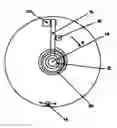
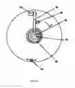
FIGS. 1 and 2 are schematic diagrams of the electric brake; and
FIG. 3 depicts an electric braking system of the prior art.
DETAILED DESCRIPTION OF THE PREFERRED EMBODIMENTS
In the following description given by way of example, FIG. 1 shows the motor shaft 10 (secured to the screw with the same numeral 10 as that in FIG. 6 of the above referenced patent, that figure, referenced FIG. 3, being appended to the present patent by way of indication). A hub 12 is mounted with the freedom to rotate on this shaft 10. This hub bears an arm 14 which, in this instance, is pressed against an electromagnet 20, the latter, when powered, holds it in this position. A spiral spring 18 applies to the arm 14 a force which tends to cause it to rotate in the direction A with a torque, in automotive applications, at least equal to 3 Nm at the end of stroke. The direction of movement A corresponds to that of applying the brake that it is actuating, and this direction can be reversed if the specific features of the screws and grooves of said brake so justify. An end stop 22 will limit the stroke of the arm 14, notably if this limit cannot be afforded by the limit of the stroke of the moving parts of the brake. A finger 16, secured to the rotor of the motor, will provide the connection between this device that forms the subject of the invention and the actual brake proper.
On each power up of the brake, the motor, while releasing the brake, will, via the finger 16, press the arm 14 against the electromagnet 20 in a movement in the opposite direction to A (the torque required will be the opposite of that required for braking, but have the same order of magnitude). The powered electromagnet will hold the arm 14 in position, with the spring 18 tensioned to the maximum representing the storage of energy. The finger 16 will therefore be able to move freely in the space comprised between the two end points of its stroke that are represented by the electromagnet 20 and the end stop 22 (or the limit of the stroke of the moving parts of the brake). Thus, with the assembly powered, the power-off braking device will have absolutely no impact on the performance of the brake which will therefore be able to move freely in all the space liable to be used for the various braking operations.
In the event of a loss of power, for accidental or deliberate reasons, the electromagnet 20 will release the arm 14 which, under the stressing of the spring 18, will become pressed firmly against the end stop 22 (or the limit of the stroke of the moving parts of the brake) and in this movement it will carry along with it the finger 16 (whatever the position thereof between 20 and 22) and thus, through the rotor of the motor, cause the brake force to be applied at its maximum value and maintained. FIG. 2 depicts the layout of the various components in this new configuration.
Claims
1. An electric brake, comprising brake pads and a brake motor, wherein on each power up of the brake, said brake motor actuates an energy storage device (10, 12, 14, 16, 18) whereas, for each power down of the brake, stored energy is used to produce no-power braking, said no-power braking is maintained until power is next applied to the brake.
2. The electric brake as claimed in claim 1, wherein the energy storage device comprises at least one spring (18), the stored energy comprising mechanical energy.
3. The electric brake as claimed in claim 2, wherein the energy storage device comprises a motor shaft (10) secured to a spindle of the brake motor, a finger (16) secured to the motor shaft (10) and an arm (14) free to rotate about the motor shaft (10), wherein the storage of energy is performed when the finger (16) driven by the motor pushes the arm (14).
4. The electric brake as claimed in claim 3, wherein the arm (14) is held by an electromagnet (20), to stress the at least one spring (18), from a time that power is applied to the electric brake until power ceases to be applied.
5. The electric brake as claimed in claim 4, wherein the power down of the electromagnet (20) releases the arm (14) such that the at least one spring (18) moves the arm (14) in a first direction until it comes into contact with an end stop (22) in order to achieve no-power braking, said no-power braking is maintained until power is reapplied to the brake.
6. The electric brake as claimed in claim 1, further comprising a variable mechanical gain system positioned between the motor shaft and the brake pad clamping system.
7. The electric brake as claimed in claim 5, wherein the end stop (22) limits the stroke of the arm during no-power braking so that the moving parts are protected, the stroke of the arm (14) being less than half a turn.
8. The electric brake as claimed in claim 1, wherein the energy storage device comprises a capacitor.
9. The electric brake as claimed in claim 7, wherein:
a force applied by the brake pads to the disk is substantially 15 kN,
an elastic deformation of the brake pad supports is about 1 mm,
a torque applied by the at least one spring (18) to the arm (14) is greater than 3 Nm upon contact with the end stop (22) for an angular amplitude of movement of the arm (14) of about 2.5 rad.
Images & Drawings included:


Sources:
- United States Patent and Trademark Office - verify current appl. status at the USPTO↗
Recent applications in this class:
- » 20250277518 2025-09-04
PISTON FOR DISC BRAKE DEVICE AND DISC BRAKE DEVICE - » 20250271042 2025-08-28
BRAKE ACTUATOR FOR A FRICTION BRAKE, FRICTION BRAKE AND VEHICLE - » 20250271041 2025-08-28
ELECTROMECHANICAL BRAKE - » 20250237279 2025-07-24
ELECTRIC BRAKE DEVICE - » 20250207649 2025-06-26
ELECTROMECHANICALLY ACTUATABLE BRAKE PISTON ASSEMBLY - » 20250207648 2025-06-26
A BRAKE COMPONENT - » 20250207647 2025-06-26
BRAKE ACTUATOR AND BRAKE APPARATUS INCLUDING THE SAME - » 20250207646 2025-06-26
BRAKE ACTUATOR AND BRAKE APPARATUS INCLUDING THE SAME - » 20250198473 2025-06-19
ELECTRO-MECHANICAL BRAKE APPARATUS WITH OFFSET TRANSMISSION SHAFT OF REDUCER, SYSTEM, AND VEHICLE - » 20250189002 2025-06-12
SEAL ASSEMBLY FOR A BRAKE PISTON ASSEMBLY