Card tray of electrical connector assembly having a front surface feature for increasing a withdrawn travel distance
US20200074248A1
2020-03-05
16/553,195
2019-08-28
✅ Patent granted
US 10,909,430 B2
2021-02-02
-
-
Abdullah A Riyami | Justin M Kratt
Wei Te Chung | Ming Chieh Chang
2039-08-28
Abstract:
A card connector assembly includes: an electrical connector including an insulative housing, a plurality of terminals secured to the insulative housing, a shell covering the insulative housing to form a receiving cavity, and an ejector having a pivot; and a card tray removably received in the receiving cavity, the card tray having a front surface, wherein the card tray has a protrusion at the front surface, and the pivot has an engaging portion for ejecting the card tray, the engaging portion having a recess for receiving the protrusion and an ejecting end for riding onto the protrusion.
Assignee:
- FOXCONN INTERCONNECT TECHNOLOGY LIMITED 922 Grand Cayman, Cayman Islands
- FOXCONN (KUNSHAN) COMPUTER CONNECTOR CO., LTD. 228 🇨🇳 Kunshan, China
Applicant:
Interested in similar patents?
Get notified when new applications in this technology area are published.
Classification:
G06K13/0818 » CPC main
Conveying record carriers from one station to another, e.g. from stack to punching mechanism the record carrier having longitudinal dimension comparable with transverse dimension, e.g. punched card; Feeding or discharging cards using an arrangement for ejection of an inserted card the ejection arrangement utilizing a push bar for manipulation by hand in order to eject the inserted card the push bar comprising a pivotable push button
G06K7/0056 » CPC further
Methods or arrangements for sensing record carriers, e.g. for reading patterns by galvanic contacts, e.g. card connectors for ISO-7816 compliant smart cards or memory cards, e.g. SD card readers housing of the card connector
G06K13/0831 » CPC further
Conveying record carriers from one station to another, e.g. from stack to punching mechanism the record carrier having longitudinal dimension comparable with transverse dimension, e.g. punched card; Feeding or discharging cards using an arrangement for ejection of an inserted card the ejection arrangement comprising a slide, carriage or drawer
G06K7/00 IPC
Methods or arrangements for sensing record carriers, e.g. for reading patterns
G06K13/08 » CPC further
Conveying record carriers from one station to another, e.g. from stack to punching mechanism the record carrier having longitudinal dimension comparable with transverse dimension, e.g. punched card Feeding or discharging cards
G06K13/0806 » CPC further
Conveying record carriers from one station to another, e.g. from stack to punching mechanism the record carrier having longitudinal dimension comparable with transverse dimension, e.g. punched card; Feeding or discharging cards using an arrangement for ejection of an inserted card
G06K13/0812 » CPC further
Conveying record carriers from one station to another, e.g. from stack to punching mechanism the record carrier having longitudinal dimension comparable with transverse dimension, e.g. punched card; Feeding or discharging cards using an arrangement for ejection of an inserted card the ejection arrangement utilizing a push bar for manipulation by hand in order to eject the inserted card
G06K13/0825 » CPC further
Conveying record carriers from one station to another, e.g. from stack to punching mechanism the record carrier having longitudinal dimension comparable with transverse dimension, e.g. punched card; Feeding or discharging cards using an arrangement for ejection of an inserted card the ejection arrangement being of the push-push kind
H01R13/2442 » CPC further
Details of coupling devices of the kinds covered by groups or -; Contact members; Contacts for co-operating by abutting resilient; resiliently-mounted with a single cantilevered beam
H01R13/62938 » CPC further
Details of coupling devices of the kinds covered by groups or -; Means for facilitating engagement or disengagement of coupling parts or for holding them in engagement; Additional means for facilitating engagement or disengagement of coupling parts, e.g. aligning or guiding means, levers, gas pressure electrical locking indicators, manufacturing tolerances; Comprising exclusively pivoting lever Pivoting lever comprising own camming means
H05K5/0295 » CPC further
Casings, cabinets or drawers for electric apparatus; Details of interchangeable modules or receptacles therefor, e.g. cartridge mechanisms; Receptacles therefor, e.g. card slots, module sockets, card groundings having ejection mechanisms
H05K5/0295 » CPC further
Casings, cabinets or drawers for electric apparatus; Details of interchangeable modules or receptacles therefor, e.g. cartridge mechanisms; Receptacles therefor, e.g. card slots, module sockets, card groundings having ejection mechanisms
H01R13/629 IPC
Details of coupling devices of the kinds covered by groups or -; Means for facilitating engagement or disengagement of coupling parts or for holding them in engagement Additional means for facilitating engagement or disengagement of coupling parts, e.g. aligning or guiding means, levers, gas pressure electrical locking indicators, manufacturing tolerances
H01R13/24 IPC
Details of coupling devices of the kinds covered by groups or -; Contact members; Contacts for co-operating by abutting resilient; resiliently-mounted
H05K5/02 IPC
Casings, cabinets or drawers for electric apparatus Details
H05K5/02 IPC
Casings, cabinets or drawers for electric apparatus Details
Description
BACKGROUND OF THE INVENTION
1. Field of the Invention
The present invention relates to an electrical connector assembly having a card tray with an integral feature for achieving a relatively long travel distance during ejecting the card tray for ease of subsequent withdrawal.
2. Description of Related Arts
Taiwan Patent No. 600230 discloses a card connector assembly comprising: an electrical connector including an insulative housing, a plurality of terminals secured to the insulative housing, a shell covering the insulative housing to form a receiving cavity, and an ejector having a pivot; and a card tray removably received in the receiving cavity. The card tray has a flat front surface and the pivot has an engaging portion for ejecting the card tray. A travel distance of the card tray during its withdrawal by such ejector is limited. It is desired to increase a travel distance when ejecting a card tray without changing a general length of its pivot engaging portion.
SUMMARY OF THE INVENTION
A card connector assembly comprises: an electrical connector including an insulative housing, a plurality of terminals secured to the insulative housing, a shell covering the insulative housing to form a receiving cavity, and an ejector having a pivot; and a card tray removably received in the receiving cavity, the card tray having a front surface, wherein the card tray has a protrusion at the front surface, and the pivot has an engaging portion for ejecting the card tray, the engaging portion having a recess for receiving the protrusion and an ejecting end for riding onto the protrusion.
BRIEF DESCRIPTION OF THE DRAWING
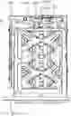
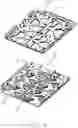
FIG. 1 is a perspective view of a card connector assembly in accordance with a first embodiment of the present invention;
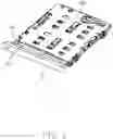
FIG. 2 is an exploded view of the card connector assembly;
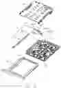
FIG. 3 is partially assembled view of the card connector assembly in FIG. 2;
FIG. 4 is an exploded view of an electrical connector of the card connector assembly;
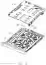
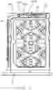
FIG. 5 is a plan view showing a card tray of the card connector assembly at an inserted position;
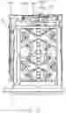
FIG. 6 is a plan view showing the card tray at a withdrawn position; and
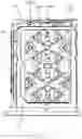
FIG. 7 is a plan view showing confrontation between the card tray and the pivot in the inserted position according to a second embodiment of the invention.
DETAILED DESCRIPTION OF THE PREFERRED EMBODIMENT
Referring to FIGS. 1 to 6, a card connector assembly comprises: an electrical connector 100 including an insulative housing 1, a plurality of terminals 2 secured to the insulative housing 1, and a shielding shell 3 covering the insulative housing 1 to form a receiving cavity 30; a card tray 5 removably received in the receiving cavity 50 between an inserted position (FIG. 5) and a withdrawn position (FIG. 6); and an ejector 4. The electrical connector may further include a metal frame 6 secured to the insulative housing 1 and engaged with the shell 3.
The terminals 2 are insert molded with the insulative housing 1 and each has a contacting portion 21. The ejector 4 includes an operating rod 41 and a pivot 42 coupled to the operating rod 41. The operating rod 41 and the pivot 42 are preferably metallic. The pivot 42 includes a coupling portion 421 and an engaging portion 422. The engaging portion 422 has an engaging surface 4221 for contacting a front surface 50 of the card tray 5 carrying electronic card or cards or even a front surface of an electronic card itself in the case of doing without a card tray. The operating rod 41 has a slot 411 for receiving the coupling portion 421. The metal frame 6 may be insert molded with the insulative housing 1. The insulative housing 1 has a post 111 and the pivot 42 has a hole 423 so that the pivot 42 is rotatably supported by the insulative housing 1. The metal frame 6 has a reinforcing member 61 positioned inside the post 111 for strengthening purpose.
In order to increase a withdrawn travel length of the card tray 5 for subsequent ease of removal or access, the engaging surface 4221 has a recess 4222 and the card tray 5 has a protrusion 51 at the front surface 50 to be received in the recess 4222. When the operating rod 41 is pushed to rotate the pivot 42, the card tray 5 is moved by the engaging portion 422 while the protrusion 51 leaves the recess 4222, and a free end 424 of the engaging portion 422 adjacent to the recess 4222 in turn engages or rides onto the protrusion 51. Presence of the protrusion 51 that the adjacent end of the engaging portion 422 rides onto results in an increased travel length of the card tray during ejecting. Preferably, the card tray 5 is metallic. The recess 4222 has a guiding surface 4223 at a junction with the free end 424; the protrusion 51 has a corresponding guiding surface 511. The guiding surface 4223 makes a smooth transition from the recess 4222 to the free end 424.
In one sense, a portion of the free end 424 protrudes relative to the recess 4222. In another sense, the protrusion 51 of the card tray 5 is positioned at a different level/position along the traveling direction from the front surface 50, as is a recess were it disposed to receive the protruding portion of the free end 424 of the engaging portion 422. For example, FIG. 7 essentially shows the recess (not labeled) formed in a front end region (not labeled) of the card tray 5 to receive the free end 424. In brief, the spirit of the invention is to have the free end 424 of the pivot 42 and a front end region of the card tray 5 are at least partially overlapped in the transverse direction perpendicular to the mating/inserting/ejecting/traveling direction so as to increase the traveling distance during ejection. In contrast, in the traditional design, the engaging free end of the pivot only intimately confronts the front end region of the card tray in the mating/inserting/ejecting/traveling direction without any overlapping in the transverse direction.
Claims
What is claimed is:1. A card connector assembly comprising:
an electrical connector including an insulative housing, a plurality of terminals secured to the insulative housing, a shell covering the insulative housing to form a receiving cavity, and an ejector having a pivot; and
a card tray removably received in the receiving cavity between an inserted position and a withdrawn position, the card tray having adjacent first and second front surfaces positioned at different levels; wherein
the pivot has an ejecting end engaging the first front surface when the card tray is at the inserted position while engaging the second front surface when the card tray is at the withdrawn position.
2. A card connector assembly comprising:
an electrical connector including an insulative housing, a plurality of terminals secured to the insulative housing, a shell covering the insulative housing to form a receiving cavity, and an ejector having a pivot; and
a card tray removably received in the receiving cavity, the card tray having a front surface; wherein
the card tray has a protrusion at the front surface; and
the pivot has an engaging portion for ejecting the card tray, the engaging portion having a recess for receiving the protrusion and an ejecting end for riding onto the protrusion.
3. The card connector assembly as claimed in claim 2, wherein the card tray is metallic.
4. The card connector assembly as claimed in claim 2, wherein:
the insulative housing has a post supporting the pivot; and
the electrical connector comprises a metal frame secured to the insulative housing and engaged with the shell, the metal frame having a reinforcing member positioned inside the post.
5. A card connector assembly comprising:
an electrical connector including an insulative housing, a plurality of terminals secured to the insulative housing, a shell covering the insulative housing to form a receiving cavity, and an ejector operable from an exterior and having a pivot having an engaging free end; and
a card tray removably received in the receiving cavity along an ejecting direction, the card tray having a front end region to intimately confront the engaging free end of the pivot in said ejecting direction; wherein
the engaging free end of the pivot and the front end region of the card tray are at least partially overlapped with each other in a transverse direction perpendicular to the ejecting direction.
6. The card connector assembly as claimed in claim 5, wherein a protrusion is formed on a front face of the front end region of the card tray and overlapped with the engaging free end of the pivot in the transverse direction.
7. The card connector assembly as claimed in claim 6, wherein the pivot forms a recess to receive said protrusion.
8. The card connector assembly as claimed in claim 5, wherein the front end region of the card tray forms a recess to receive the engaging free end of the pivot.
Images & Drawings included:
Sources:
- United States Patent and Trademark Office - verify current appl. status at the USPTO↗
Recent applications for this Assignee:
- » 20240199157 2024-06-20
METHOD OF CONTROLLING STATE OF ELECTRIC ASSIST BICYCLE, CONTROL SYSTEM, AND ELECTRONIC DEVICE - » 20240177887 2024-05-30
CORE WIRE AND METHOD OF MAKING SAME AND CABLE INCLUDING THE CORE WIRE - » 20240072477 2024-02-29
ELECTRICAL CONNECTOR WITH IMPROVED CONTACTS - » 20240072477 2024-02-29
ELECTRICAL CONNECTOR WITH IMPROVED CONTACTS - » 20240055792 2024-02-15
Electrical connector having an angled part and a U-shaped plate together defining a tubular structure - » 20240055792 2024-02-15
Electrical connector having an angled part and a U-shaped plate together defining a tubular structure - » 20230352880 2023-11-02
ELECTRICAL CONNECTOR WITH IMPROVED INSERTING MEMBER - » 20230352880 2023-11-02
ELECTRICAL CONNECTOR WITH IMPROVED INSERTING MEMBER - » 20230335934 2023-10-19
ELECTRICAL CONNECTOR - » 20230335934 2023-10-19
ELECTRICAL CONNECTOR