RFID tag for harsh environment inductively coupled in double loop
US20200076048A1
2020-03-05
16/609,260
2017-12-19
✅ Patent granted
US 11,128,027 B2
2021-09-21
WO; PCT/RO2017/000023; 20171219
WO; WO2018/231083; 20181220
April G Gonzales
The Roy Gross Law Firm, LLC | Roy Gross
2037-12-19
Abstract:
The invention relates to an IDRF label for use in aggressive environments. The IDRF label (1) according to the invention comprises a UIF-SIF (2) antenna made of an electrically conductive textile, electrically insulated, embroidered on a textile backing, an IDRF transponder (3) and a textile substrate (4) and the UIF-SIF antenna (2), the whole assembly being sealed by hot-dipping a second textile substrate, wherein the UIF-SIF (2) antenna has a central loop formed by a loop (5) by which it inductively couples with the encapsulated IDRF transponder 3.
Assignee:
- PROMAR TEXTIL INDUSTRIES S.R.L. 2 🇷🇴 Brasov, Romania
Applicant:
Interested in similar patents?
Get notified when new applications in this technology area are published.
Classification:
H01Q1/2225 » CPC main
Details of, or arrangements associated with, antennas; Supports; Mounting means by structural association with other equipment or articles associated with components used in interrogation type services, i.e. in systems for information exchange between an interrogator/reader and a tag/transponder, e.g. in Radio Frequency Identification [RFID] systems used in active tags, i.e. provided with its own power source or in passive tags, i.e. deriving power from RF signal
G06K19/07773 » CPC further
Record carriers for use with machines and with at least a part designed to carry digital markings characterised by the kind of the digital marking, e.g. shape, nature, code; Record carriers with conductive marks, printed circuits or semiconductor circuit elements, e.g. credit or identity cards also with resonating or responding marks without active components with integrated circuit chips; Constructional details, e.g. mounting of circuits in the carrier the record carrier being capable of non-contact communication, e.g. constructional details of the antenna of a non-contact smart card Antenna details
H01Q1/40 » CPC further
Details of, or arrangements associated with, antennas Radiating elements coated with or embedded in protective material
H01Q7/00 » CPC further
Loop antennas with a substantially uniform current distribution around the loop and having a directional radiation pattern in a plane perpendicular to the plane of the loop
H04B5/0062 » CPC further
Near-field transmission systems, e.g. inductive loop type for use in interrogation, identification or read/write systems in RFID [Radio Frequency Identification] Systems
H04B5/0068 » CPC further
Near-field transmission systems, e.g. inductive loop type for use in interrogation, identification or read/write systems in transponders
H04B5/0081 » CPC further
Near-field transmission systems, e.g. inductive loop type using inductive coupling with antenna coils
H04B5/00 IPC
Near-field transmission systems, e.g. inductive loop type
H01Q1/22 IPC
Details of, or arrangements associated with, antennas; Supports; Mounting means by structural association with other equipment or articles
G06K19/077 IPC
Record carriers for use with machines and with at least a part designed to carry digital markings characterised by the kind of the digital marking, e.g. shape, nature, code; Record carriers with conductive marks, printed circuits or semiconductor circuit elements, e.g. credit or identity cards also with resonating or responding marks without active components with integrated circuit chips Constructional details, e.g. mounting of circuits in the carrier
H01Q1/14 » CPC further
Details of, or arrangements associated with, antennas; Supports; Mounting means for wire or other non-rigid radiating elements
Description
A Minimum Radio Frequency Identification (RFID) system consists of a interrogator reader connected to a PC and a population of tags attached to the products they uniquely identify. An application software handles RFID information to trace and inventory these products. Passive RFID tags operating in the UIF (860-960 MHz) or SIF (2.45 GHz) frequency range are used.
Objects identified using RFID tags and intended for use in harsh environments shall withstand the following requirements:
-
- repeated immersion in the aquatic environment
- exposure to high temperatures of up to 200° C., more than 20 minutes
- high temperature variations—(8° C./90° C.),
- corrosive chemicals
- mechanical pressures of 40-60 bar,
- repeated mechanical stresses (bending, pressing, etc.)
- number of cycles of use greater than 300
From a historical point of view, for RFID applications, passive RFID tags operating in the HF domain (13.65 MHz) were used first. Constructively, they were made up of an integrated circuit galvanically connected to a multi-spiral coil. The reading range was under one meter, and the reading speed was about one label per second. With the introduction of passive RFID tags operating in the UHF range, and with the development of communications protocols, performance has increased spectacularly at high read speeds (10 RFID tags/sec) and read ranges of up to 7 m.
For textile tracking applications, the design of an RFID tag composed of a capsulated traponder, thus protected by the harsh environment of industrial laundries, and a UHF antenna made of metallic wire, has been widely adopted. The encapsulated transponder contains an integrated circuit and a near-field antenna by which it is inductively coupled to a segment of the UHF antenna.
This category includes the RFID UHF tags, the subject of patents EP 2405054 A1, DE 102007026720 A1, US 20090079574 A1.
But even this design has its limits. Capsulation is achieved by protecting the contacts between the integrated circuit (IC) pins and the near field antenna terminals, but at the UHF antenna there are major discrepancies relative to the mechanical and thermal characteristics of the textile substrate relative to the metallic conductors of the UHF antenna.
- Here's a short list of problems with using these labels in industrial laundries:
- loosening the seams and breaking the textile fabric, to which the RFID tag is attached,
- the metal wire from which the UHF antenna is made oxidizes in contact with the water and the oxidant chemicals used in the washing process, stains the fabric and compromises its appearance. Also due to oxidation the electrical parameters of the antenna material, and implicitly its electromagnetic performances, are affected.
- the material of the metal wire from which the antenna is made stores much more thermal energy than the textile support, this difference leading to the piercing/perforation of the textile material by the metal wire of the antenna that protrudes out of it.
- because of the rigidity of the metal wire, the entire tag is a little flexible compared to the textile material from which the article to be identified is being made. Low flexibility creates break lines on the RFID tagline.
- These lead to the detachment of the encapsulated RFID transponder 3 and consequently to the loss of the identity of the textile objects being monitored, to the appearance problems of the textile item, but especially to the problems for the customers, respectively their injury to the use of textile articles (towels, pillows, sheets) that were pierced by the metal wires.
- At the same time, current UHF tags have considerable dimensions that make them inappropriate, unsightly for identifying small items (tablecloths).
The ideal passive RFID tag for the identification of textile items that are maintained in laundries and dry cleaners is:
-
- electromagnetic performance (high reading distance),
- of small size,
- flexible and resistant to bending,
- resistant to chemical stress,
- resistant to a number of exposures greater than the product it identifies, over 200 washing cycles.
- So an electromagnetically performant, resistant and discreet RFID tag.
The ways to approach this ideal prototype are:
-
- the use of encapsulating materials to effectively protect the integrated circuit and its contacts with the near field antenna at the transponder level,
- designing a UHF/SHF antenna geometry to give it superior electromagnetic properties and at the same time to have as small a size as possible,
- use of electrically conductive materials with mechanical parameters close to the textile, to the construction of the UHF/SHF antenna
- tag components that are in direct interaction, have close thermal expansion coefficients.
The UHF antennas of the RFID tags available on the market are made of electrically insulated metallic wire, attached to a textile support by sewing or embroidering. They have the meandered shape (EP 2405054 A1), or crossed loops (WO 2013128299 A1). All have the vulnerabilities and limitations described in paragraph [0006].
The present invention overcomes the aforementioned drawbacks associated with prior art solutions by providing a tag having the features mentioned in the independent claim 1.
Other preferred features of the present invention are set forth in the appended dependent claims.
The present invention proposes for the UHF-SHF antenna an electroconductive yarn made of metallic stainless steel wire that resists the action of oxidizing agents. By using the electroconductive textile wire to make the UHF-SHF antenna, due to its flexibility, the electroconductive textile thread allows for the realization of geometries impossible to achieve with an electrically isolated metal wire. It is possible to make very small radius curves without creating mechanical stresses in the tag structure. Also the UHF-SHF antenna made of electroconductive textile thread is very discreet and does not feel, it naturally integrates into the textile material of the product it identifies.
Other features and advantages of the present invention will become more apparent from the following detailed description, given in connection with the accompanying drawings, in which:
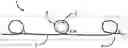
FIG. 1 shows a schematic view of the double-loop RFID tag according to a first embodiment of the invention;
FIG. 2 shows a the double loop in detail according to the first embodiment of the invention;
FIG. 3 shows a schematic view of the double-loop RFID tag according to a second embodiment of the invention;
The UHF-SHF antenna 2 has a particularly innovative geometry characterized in that it has in the central region a double loop 5 through which an efficient inductive coupling with the encapsulated RFID transponder 3 is provided, thereby obtaining an electromagnetically efficient RFID tag.
The double loop 5 also allows for a small, discreet and easy-to-integrate RFID tag even in small-sized textile articles.
The RFID passive UHF-SHF antenna can be made in two variants FIG. 2 and FIG. 3. In the first embodiment, FIG. 2, the electroconductive textile thread is electrically insulated and allows the thread overlapping at certain points (A, B, C, D) without electrical contact. For the second embodiment, FIG. 3, the UHF-SHF antenna geometry allows the use of a non-insulated electroconductive textile thread. Both variants are embroidered.
In the first embodiment, FIG. 2, the double loop 5 of the UHF antenna 2 through which the inductive coupling with the encapsulated RFID transponder 3 is made, has created an UHF antenna with efficient power transfer and information integrity, with substantially reduced design dimensions. There is no electrical contact at points A, B, C, and D.
In the second embodiment of the UHF-SHF antenna, FIG. 3, the drawing of the embroidery is made so that the electroconductive textile thread is continuously embroidered without crossings in its path.
- After embroidering, by bending over the dotted line and overlapping the two P and Q loops, a double loop (5) will form. The loop P has a smaller diameter than the Q loop. It is noted that, after bending and overlap, the currents in the two loops have the same direction, contributing together to an efficient inductive coupling. Prior to bending between the two loops P and Q, the encapsulated transponder (3) will be fixed with adhesive on the loop P. After folding and overlapping the encapsulated transponder (3) will be secured between the two loops P and Q.
The present invention is complementary to patent No. a 2016 00791, which proposed an RFID Transponder designed to operate in aggressive environments. The RFID transponder was described as being designed to be used both independently for RFID applications for which the reading range is in centimeters and with a UHF-SHF antenna for RFID applications for which the reading range is of meters order.
The design of this tag by embedding in its structure the encapsulated transponder 3, object of the patent a 2016 00791, overcomes the problems created by the dimensional discrepancies between tiny integrated cicuits and the antennas, they are galvanically connected, which require the use of expensive technologies (wire bonding) or inadequate to the harsh environment of industrial laundry (bonding with conductive adhesives).
The tag design looks for a straight measure relative to the dimensions of the objects it identifies and the size of the tag. It does not fall into excessive miniaturization when it is not necessary.
A maximal design is proposed for the maximum achievable design with the currently available components, keeping the measure.
-
- transponder with a minimum number of galvanic contacts, equal to the number of active, integrated circuit pins, robust galvanic contacts using an integrated circuit in SOT323 package, welded in the cheap and mature SMT technology, at the near-field antenna terminals, encapsulated and thus protected from the harsh environment of industrial laundry,
- inductive coupling between encapsulated transponder (3) and UIF-SIF antenna (2),
- the homogeneity of the components of the UIF-SIF antenna (2)—textile substrate and the antenna, both of textile material,
- substantially reduced length of the tag by using the double loop of the UHF-SHF antenna.
- a tag born and not made for the textile world by the materials used (textile thread on a textile substrate), and the methods of making (embroidering the textile thread on the textile substrate).
| Referin e bibliografice |
| Brevet citat | Data inregistrarii | Data publicării | Solicitant | Titlul |
| EP 2405054 A1 | 07 lulie 2010 | 11 lanuarie 2012 | Datamars | Textile item |
| SA (CH) | identification tag | |||
| DE 102007026720 | 06 lunie 2007 | 11 Decembrie | Bielomatik | Chip module for an |
| A1 | 2008 | RFID system | ||
| US 20090079574 | 19 Septembrie | 26 Martie 2009 | Noriyuki | Rfid tag |
| A1 | 2008 | |||
| WO 2013128299 | 02 Martie 2012 | 06 Septembrie | Usta | Enhanced antenna |
| A1 | 2013 | structure for RFID tags | ||
Claims
1. An RFID tag (1) for use in harsh enviroments comprising an UHF-SHF antenna (2) made from a continuous electroconductive textile thread, electrically insulated, embroided on textile substrate, an RFID transponder (3) and a substrate of textile material (4) on which the RFID transponder (3) and the UHF-SHF antenna (2) are placed, the whole assembly being sealed by hot-dipping of a second textile substrate, characterized in that the UHF-SHF antenna (2) has a central zone formed by a double loop (5) by which it inductively couples with the encapsulated RFID transponder (3).
2. The RFID tag (1) according to claim 1, characterised in that the UHF-SHF antenna (2) is made of an electroconductive textile thread, electrically insulated, by continuous embroidering, starting from one end to the other, and has simple loops in each extremity, and in the central area a double loop (5) consisting of a first loop with a smaller diameter, followed by a second concentric loop with a larger diameter.
3. The RFID tag (1) according to claim 1, characterized in that the UHF-SHF antenna (2) does not show electrical contacts in the crossing points (C and D) in the construction of the simple loops located at the extremities nor in the crossing points (A and B) by which the central loop (5) is formed.
4. The RFID tag (1) according to claim 1, characterized in that the UHF-SHF antenna (2) is made by cotinuous embroidering of the elctroconductive textile thread in the form of two open loops disposed in a upper plane in relation to the longitudinal direction and two open loops disposed in a lower plane in relation to the same longitudinal direction.
5. The RFID tag (1) according to claim 4, characterized in that, in the central area, the upper plane loop (P) has a smaller diameter than the loop (Q) from the lower plane, the transponder (3) being fixed and centered on the loop (P) in the upper plane, and the loop (Q) from the lower plane will overlapp the loop (P)) from the upper plane by bending over said longitudinal direction, so that the double loop (5) is created having the transponder (3) inside it.
Images & Drawings included:

Sources:
- United States Patent and Trademark Office - verify current appl. status at the USPTO↗
Recent applications in this class:
- » 20250167425 2025-05-22
SURGICAL SPONGES WITH FLEXIBLE RFID TAGS - » 20250141087 2025-05-01
ANTENNA INLAY FOR A DOCUMENT AND DOCUMENT WITH SUCH AN ANTENNA INLAY - » 20250038395 2025-01-30
RFID Antenna - » 20240235005 2024-07-11
SURGICAL SPONGES WITH FLEXIBLE RFID TAGS - » 20240136700 2024-04-25
Surgical sponges with flexible RFID tags - » 20240097310 2024-03-21
WIRELESS SENSOR WITH EXTENDED POWER FOR USE WITH SPACECRAFT - » 20240039140 2024-02-01
Modular Antenna for an RFID Reading Device - » 20240014542 2024-01-11
WIRELESS PASSIVE ELECTRONIC COMPONENT AND ASSOCIATED READING SYSTEM - » 20230395966 2023-12-07
RFID TAG AND MANUFACTURING METHOD THEREOF - » 20230335881 2023-10-19
MOUNTING MEMBER WITH RFID TAG, MANUFACTURING METHOD FOR MOUNTING MEMBER WITH RFID TAG, HEAD UNIT OF MOUNTING MEMBER WITH RFID TAG, AND RFID TAG MOUNT UNIT
Recent applications for this Assignee:
- » 20190279068 2019-09-12
Radio-frequency identification transponder for aggressive environments