LIGHTING DEVICE, IN PARTICULAR LIGHTING DEVICE FOR A VEHICLE
US20220186899A1
2022-06-16
17/310,486
2019-02-21
✅ Patent granted
US 12,613,018 B2
2026-04-28
WO; PCT/EP2019/054284; 20190221
WO; WO2020/169197; 20200827
Matthew J. Peerce
Husch Blackwell LLP
2039-02-21
Abstract:
A Lighting device, in particular lighting device for a vehicle, is provided comprising at least one light source from which light is emitted during operation of the lighting device. A first flexible foil is also provided through which the light emanating from the at least one light source passes at least partially. The first foil influences the light passing through in such a way that directed light emerges from the first foil. The lighting device also comprising a second flexible foil into which the at least one light source is integrated or on which the at least one light source is arranged.
Assignee:
- HELLA GmbH Co. KGaA 624 🇩🇪 Lippstadt, Germany
Applicant:
Interested in similar patents?
Get notified when new applications in this technology area are published.
Classification:
F21S41/285 » CPC further
Illuminating devices specially adapted for vehicle exteriors, e.g. headlamps characterised by refractors, transparent cover plates, light guides or filters Refractors, transparent cover plates, light guides or filters not provided in groups -
F21S41/19 » CPC main
Illuminating devices specially adapted for vehicle exteriors, e.g. headlamps characterised by the light source Attachment of light sources or lamp holders
F21S41/141 » CPC further
Illuminating devices specially adapted for vehicle exteriors, e.g. headlamps characterised by the light source characterised by the type of light source Light emitting diodes [LED]
F21S41/20 IPC
Illuminating devices specially adapted for vehicle exteriors, e.g. headlamps characterised by refractors, transparent cover plates, light guides or filters
Description
CROSS REFERENCE
This application claims priority to PCT Application No. PCT/EP2019/054284, filed Feb. 21, 2019, the entirety of which is hereby incorporated by reference.
FIELD OF THE INVENTION
This invention concerns a lighting device, in particular a lighting device for a vehicle.
BACKGROUND OF THE INVENTION
A lighting device of the above type is known from DE 10 2014 117 883 A1. The lighting device described therein may, for example, be designed as a headlamp of a vehicle and comprises, for example, a light source designed as a light-emitting diode (LED) or as a laser diode. The lighting device also includes a hologram through which the light from the light source passes. The hologram is especially designed as a photopolymer in the form of a flexible foil. The hologram may produce directional light so that a light distribution corresponding to a passing beam and/or a driving beam can be produced in front of the vehicle.
The problem underlying this invention is the creation of a lighting device of the type mentioned above, which can be better adapted to different requirements, in particular as regards the positioning or installation space of the lighting device.
BRIEF SUMMARY OF THE INVENTION
The lighting device shall comprise a second flexible foil in which the at least one light source is integrated or on which the at least one light source is arranged. This allows the entire lighting device to be made flexible. Such a design makes it easy to adapt the lighting device to the local requirements of the vehicle, for example. In particular, it is possible, for example, to apply the lighting device to curved surfaces. In addition, a lighting device with two foils for generating and shaping the light can be made very flat, so that the space requirements of the lighting device are low.
It may be provided that the lighting device comprises several light sources integrated into the second foil or arranged on the second foil. The number of light sources can be adapted to the function of the lighting device. For example, the at least one light source can be designed as a light-emitting diode.
It is possible that contact elements for making electrical contact with the at least one light source are arranged on the second foil, in particular laterally on the second foil. This means that even a very flat lighting device can be reliably connected.
It may be provided that the first foil and the second foil are arranged parallel to one another, in particular the two foils being spaced apart from one another. Preferably, the lighting device comprises a spacer arranged between the first and second foils, the spacer in particular also being flexible. The spacer can, for example, be designed as a frame or as a transparent plastic component. The spacer can have a suitable thickness to optimize the distance between the two foils. Furthermore, the flexibility of the spacer ensures that the entire lighting device can be designed to be flexible.
It is possible for the lighting device to comprise means for dissipating the heat generated by the at least one light source, the means being arranged in particular on the side of the second foil facing away from the first foil. The means for dissipating the heat generated by the at least one light source may, for example, be in the form of a heat-conducting paste. Despite the fact that the lighting device may be very flat, the heat generated by the light sources can be dissipated well in this way.
It may be provided that the lighting device comprises adhesive means enabling the lighting device to be fastened to a surface, the adhesive means being arranged in particular on the side of the second foil facing away from the first foil. The adhesives can be used to glue the lighting device to a curved surface such as the engine hood of a vehicle.
It is possible that the lighting device is waterproof. This allows the lighting device to be installed in an exterior space, such as the outside of a motor vehicle, without allowing water to enter the possibly sensitive electronics of the lighting device.
It may be provided that the first foil influences the light passing therethrough in such a way that a light distribution is generated which corresponds to the application purpose of the lighting device. For example, when the lighting device is designed as a headlamp of a motor vehicle, the first foil may be able to produce a suitable light distribution.
In particular, the first foil may comprise a hologram or be formed as a hologram, the hologram being in particular a replica hologram of a computer-generated master hologram. A suitable hologram design can, for example, generate a light distribution that corresponds to that of a passing beam and/or a driving beam.
BRIEF DESCRIPTION OF THE DRAWINGS
Reference is now made more particularly to the drawings, which illustrate the best presently known mode of carrying out the invention and wherein similar reference characters indicate the same parts throughout the views.
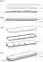
FIG. 1 is an exploded view of a lighting device according to the invention in a side view.
FIG. 2 is a side view of the lighting device according to FIG. 1 when assembled.
FIG. 3 is a perspective explosion view of the lighting device according to FIG. 1.
FIG. 4 is a perspective view of the lighting device according to FIG. 1 when assembled.
DETAILED DESCRIPTION OF THE DRAWINGS
In the figures, identical and functionally identical parts are provided with the same reference signs.
The figures depict a lighting device corresponding to the invention, which can be used, for example, as a headlamp of a motor vehicle. The lighting device comprises a first flexible foil 1, a second flexible foil 2 and a spacer 3, which is also flexible, arranged between the first foil 1 and the second foil 2.
A plurality of light sources 4 formed as light emitting diodes are arranged on the upper side of the second foil 2 as shown in FIG. 1 and FIG. 3. During operation of the lighting device, the light emitted by the light-emitting diodes propagates upwards in FIG. 1 to FIG. 4 or in the direction of the first foil 1.
Contact elements 5 for the electrical contacting of the light sources 4 are arranged on at least one end face of the second foil 2. The contact elements 5 are connected to the individual light sources 4 by means of connecting elements such as conductor paths which are not illustrated.
Only schematically indicated means 6 for dissipating the heat generated by the light sources 4 are arranged on the lower side of the second foil 2 shown in FIGS. 1 to 4 or on the side of the second foil 2 facing away from the light sources 4. The means 6 for dissipating the heat generated by the light sources 4 are designed as heat conducting paste.
On the lower side of the second foil 2 shown in FIGS. 1 to 4, or on the side of the second foil 2 facing away from the light sources 4, there are also adhesives 7, which enable the lighting device to be attached to a surface. The adhesives 7, for example, can be designed as a double-sided adhesive tape applied from below to the surface of the second foil 2, which surrounds the heat-conducting paste.
The first foil 1 comprises a hologram or is designed as a hologram, whereby the hologram is in particular a replica hologram of a computer-generated master hologram. The hologram can influence the light emitted by light sources 4 in such a way as to generate a light distribution appropriate to the application purpose of the lighting device. In particular, a typical light distribution of a headlamp can be generated.
The first foil 1 and the second foil 2 are parallel and spaced from each other. It is possible that the foils are not arranged parallel to each other. The spacer 3, which is arranged between the two foils 1, 2, can in particular consist of silicone. The spacer 3 has a suitable thickness to optimize the distance between the two foils 1, 2. At a suitable distance, the first foil 1 can be optimally illuminated by the light of the light sources 4 so that the desired light distribution is achieved.
The spacer 3 provided in the example shown is designed as a circumferential frame with a large central opening 8 for the light to pass through. However, it is also possible to use a plate-shaped, transparent plastic part instead of a frame, through which the light from light sources 4 can pass.
FIG. 2 and FIG. 4 show the lighting device when assembled. Because both foils 1, 2 and spacer 3 are flexible, the lighting device as a whole is also flexible. It can therefore be adapted to objects with a curved surface. For example, the lighting device can be attached to a curved engine hood of a motor vehicle.
The spacer 3 and the two foils 1, 2 can be connected to each other in such a way that the lighting device is watertight.
LIST OF REFERENCE SIGNS
- 1 first foil
- 2 second foil
- 3 spacer
- 4 light source
- 5 contact element
- 6 means for dissipating heat
- 7 adhesive means
- 8 opening in a spacer in the form of a frame
Claims
1. A Lighting device comprising:
at least one light source from which light is emitted during operation of the lighting device,
a first flexible foil through which the light emanating from the at least one light source passes at least partially, the first foil influencing the light passing through in such a way that directed light emerges from the first foil, and
a second flexible foil into which the at least one light source is integrated or on which the at least one light source is arranged.
2. The lighting device according to claim 1, wherein the lighting device comprises a plurality of light sources integrated into the second foil or arranged on the second foil.
3. The lighting device according to claim 1, wherein the at least one light source is designed as a light-emitting diode.
4. The lighting device according to claim 1, wherein contact elements for making electrical contact with the at least one light source are arranged on the second foil.
5. The lighting device according to claim 1, wherein the first foil and the second foil are arranged parallel to one another.
6. The lighting device according to claim 1, wherein the lighting device comprises a spacer arranged between the first and second foils, the spacer being flexible.
7. The lighting device according to claim 6, wherein the spacer is designed as a frame or as a transparent plastic component.
8. The lighting device according to claim 1, wherein the lighting device comprises means for dissipating the heat generated by the at least one light source, the means being arranged on the side of the second foil facing away from the first foil.
9. The lighting device according to claim 8, wherein the means for dissipating the heat generated by the at least one light source are in the form of a heat-conducting paste.
10. The lighting device according to claim 1, wherein the lighting device comprises adhesive means which enable the lighting device to be fastened to a surface, the adhesive means being arranged on the side of the second foil facing away from the first foil.
11. The lighting device according to claim 1, wherein the lighting device is waterproof.
12. The lighting device according to claim 1, wherein the first foil influences the light passing therethrough in such a way that a light distribution is generated which corresponds to the application purpose of the lighting device.
13. The lighting device according to claim 1, wherein the first foil comprises a hologram or is formed as a hologram, the hologram being a replica hologram of a computer-generated master hologram.
14. The lighting device according to claim 1, wherein the lighting device is a headlight for a motor vehicle.
Images & Drawings included:

Sources:
- United States Patent and Trademark Office - verify current appl. status at the USPTO↗
Similar patent applications:
- » 20200413515
Vehicle lighting device, in particular a vehicle combined lighting device - » 20210014949
LED lighting device, particularly for vehicles - » 20220003372
Lighting module, in particular for a vehicle lighting device and a vehicle lighting device - » 20200278100
Lighting device for a vehicle, in particular an electric vehicle - » 20100195346
Optical device, in particular for an automotive vehicle, such as a lighting or signaling device - » 20140104861
Optical device, in particular for an automotive vehicle, such as a lighting or signalling device - » 20240426448
LIGHTING DEVICE FOR A MOTOR VEHICLE, IN PARTICULAR A HIGH-DEFINITION HEADLAMP - » 20090184663
Circuit for a motor vehicle, in particular for actuating a lighting device - » 20190024871
Lighting device, in particular fog light for motor vehicles - » 20240426449
LIGHTING DEVICE FOR A MOTOR VEHICLE, IN PARTICULAR A HIGH-DEFINITION HEADLAMP
Recent applications in this class:
- » 20260071730 2026-03-12
LIGHT-EMITTING MODULE INTEGRATEING A FLEXIBLE ORGANIC LIGHT-EMITTING DIODE - » 20250012417 2025-01-09
Paving Machine Lighting Assembly - » 20240377042 2024-11-14
Headlamp for a vehicle - » 20240093847 2024-03-21
Vehicle lamp with light emitting portion-side terminal - » 20240044468 2024-02-08
Vehicle-mounted light source unit - » 20230366521 2023-11-16
Vehicle lighting unit - » 20230258308 2023-08-17
Light source unit for vehicle lamp, vehicle lamp - » 20220282844 2022-09-08
Vehicular lamp - » 20220205604 2022-06-30
Headlight socket - » 20220018508 2022-01-20
Illumination device for a motor vehicle headlight
Recent applications for this Assignee:
- » 20260085628 2026-03-26
COOLANT ROUTING SYSTEM WITH COUPLING DEVICE - » 20260078885 2026-03-19
TRANSMISSIVE OPTICAL COMPONENT, LIGHT MODULE FOR A MOTOR VEHICLE LIGHTING DEVICE AND METHOD FOR THE PRODUCTION OF THE OPTICAL COMPONENT - » 20260063264 2026-03-05
HEADLAMP FOR VEHICLES - » 20260063212 2026-03-05
VALVE FOR A FLUID SYSTEM OF A VEHICLE - » 20260063211 2026-03-05
VALVE FOR A FLUID SYSTEM OF A VEHICLE - » 20260048637 2026-02-19
COOLANT SYSTEM FOR AN ELECTRIC OR HYBRID VEHICLE, AND THERMAL MANAGEMENT SYSTEM - » 20250360904 2025-11-27
ACTUATOR FOR AN ELECTROMECHANICAL VEHICLE BRAKE SYSTEM AND ELECTROMECHANICAL VEHICLE BRAKE SYSTEM - » 20250313058 2025-10-09
THERMAL SYSTEM FOR AN ELECTRIC VEHICLE - » 20250237685 2025-07-24
PROTECTIVE EARTH MONITORING SYSTEM AND METHOD - » 20250224009 2025-07-10
ELECTROMECHANICAL SPREADER DEVICE FOR A DRUM BRAKE