Semi-automatic and full automatic working system at PCP air rifles
US20220196358A1
2022-06-23
17/046,784
2019-10-22
✅ Patent granted
US 11,662,170 B2
2023-05-30
WO; PCT/TR2019/050885; 20191022
WO; WO2021/080522; 20210429
Bret Hayes
Phil IP Law Inc. | Narek Zohrabyan | Karen 'Kirk' Galoyan
2039-12-28
Abstract:
Invention relates to a system providing both semi-automatic and full-automatic feature to PCP (pre-charged pneumatic) air rifles. While semi automatic or full automatic feature is provided in PCP (pre-charged pneumatic) air rifles separately, PCP air rifle mentioned in working principle developed by us have both semi automatic and full automatic operation capability.
Applicant:
Interested in similar patents?
Get notified when new applications in this technology area are published.
Classification:
F41A19/33 » CPC main
Firing or trigger mechanisms; Cocking mechanisms; Mechanical firing mechanisms, e.g. counterrecoil firing, recoil actuated firing mechanisms having only slidably-mounted striker elements, i.e. percussion or firing pins the percussion or firing pin being movable relative to the breech-block propelled by a spring under tension in bolt-action guns Arrangements for the selection of automatic or semi-automatic fire
Description
TECHNICAL FIELD
Invention relates to a system providing both semi-automatic and full-automatic feature to PCP (pre-charged pneumatic) air rifles. While semi automatic or full automatic feature is provided in PCP (pre-charged pneumatic) air rifles separately, PCP air rifle mentioned in working principle developed by us have both semi automatic and full automatic operation capability.
BACKGROUND OF THE INVENTION
PCP air rifles are operated by means of an integrated air tube system mounted thereon and cocking catch. Air pressure of certain amounts contained in the tube produced in different volumes activates the mechanism. Thus PCP air rifle can make effective firing up to 500 meters subject to pressure and tube volume.
Said PCP air rifles have semi or full automatic operating principle. Semi-automatic rifles can make one firing per each triggering without need for setting after initial setting. With full automatic rifles, firing can continue up to magazine capacity as long as the trigger is pulled without need to set again after initial setting. On the other hand, vibration occurring with rifles working full automatically may negatively affect the magazine.
For rifles working on semi automatic working principle, firing can not be made as long as trigger remains pulled whereas for full automatic rifles trigger must be released serially in order to stop firing after pulled in order to make one firing.
PURPOSE OF THE INVENTION
PCP air rifles having semi automatic and full automatic working principle are provided with both semi automatic and full automatic working by means of one single mechanism.
When user uses level lever at semi-automatic setting by means of mechanical system provided, one single firing is made per one single trigger pulling upon one single setting for magazine. When user puts level lever in full automatic position, firing continues as long as trigger is pulled upon one single setting. Thus PCP air rifle is equipped with both semi automatic and full automatic use feature.
On the other hand, a support part is added to fix the magazine in order to protect magazine against vibration occurring particularly during full automatic firing.
DETAILED DESCRIPTION OF THE INVENTION
Description of Figures
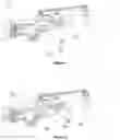
FIG. 1 General View of Rifle
FIG. 2 View of Invention on Rifle
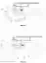
FIG. 3 Zoomed in View of Invention on Rifle
FIG. 4 Exploded View of Invention Parts
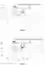
FIG. 5 View of Position Ready for Fire in Semi Automatic Position
FIG. 6 View of Trigger Tab Pulling Hold Position for Next Firing for Fired Semi Automatic Rifle
FIG. 7 View of Full Automatic Tab Pulling Hold Position where Trigger Pulled Lever Back for Full Automatic Position Rifle
FIG. 8 View of Position where in Full Automatic Position Trigger Pulled in Lever Full Automatic Tab Opened when Cock Motion Completed
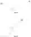
FIG. 9 View of Cock and Cock Lever
FIG. 10 View of Trigger Tab Stopper
FIG. 11 View of Level Lever
FIG. 12 View of Full Automatic Tab
FIG. 13 View of Lever
FIG. 14 View of Magazine Support Part Body
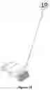
FIG. 15 View of Magazine Support Part
REFERENCE NUMBERS
- 1. Mechanism
- 2. Pellet Pusher
- 3. Pellet Pusher Pin
- 4. Lever Wedge
- 5. Lever
- 6. Cock
- 7. Trigger Tab
- 8. Trigger Case
- 9. Stopper Spring
- 10. Level Lever
- 11. Trigger Tab Stopper
- 12. Semi Automatic Trigger Sheet
- 13. Trigger
- 14. Trigger Case Cover
- 15. Full Automatic Tab Spring Cover
- 16. Full Automatic Tab Pusher Spring
- 17. Full Automatic Tab Pusher Shell
- 18. Support Screw
- 19. Magazine Support Part Tab
- 20. Magazine Support Part
- 21. Support Pin
- 22. Level Spring
- 23. Level Ball
- 24. Full Automatic Tab Housing Cover
- 25. Full Automatic Tab
- 26. Full Automatic Tab Pusher Pin
- 27. Wedge
- 28. Nozzle
- 29. Tail
This is an invention made to equip PCP air rifles with capability to operate full automatically with the development made in our rifles having semi automatic working principle. One of the main components of the invention is the level lever (10) pressed by user to activate shifting from semi automatic to full automatic system or from full automatic system to semi automatic system for PCP air rifles. Mechanical operation structure changes with level lever (10) and thus PCP air rifle gains feature of both semi automatic and full automatic operation feature.
When the level lever (10) shown in FIG. 11 is in semi automatic position (FIG. 5), trigger tab stopper (11) part in upside down T form does not make any attempt to stop trigger tab (7) thanks to stopper spring (9). When rifle is fired, cock goes forward and then comes back and trigger tab (7) moves back and goes in front of semi automatic sheet (12), cock (6) is locked into trigger tab (7) again. Cock (6) is inserted into trigger tab (7) and motion forward is prevented and re-firing can not be made. When trigger (13) is released, semi automatic trigger sheet (12) goes above trigger tab (7) and becomes ready for firing. The motions are repeated and thus semi automatic operation is provided.
When level lever (10) is put in full automatic position, trigger tab stopper (11) part moves upward the connection housing in vertical rectangular form rounded on short edges. Thus trigger tab stopper (11) moves ahead of trigger tab (7). Whenever trigger (13) is pressed, cock (6) is released from trigger tab (7) and initiates firing. Thus trigger tab (7) leans on trigger tab stopper (11) part and is not released from semi automatic trigger sheet (12) and does not go into position to hold trigger cock (6). The cock (6) repeats firing motion.
For full automatic firing, the cock (6) is to run in harmony with sheet pusher (2) combining pellet pusher pin (3) and lever wedge (4). Unless pellet pusher (2) motion is completed, next firing should not be made by the cock (6). In order to solve this issue, the mechanism (1) is added full automatic tab (25) in form of plane without wings, which is shown in FIG. 12 and is one of main factors of our invention.
When the cock (6) returns, full automatic tab pusher shell (17) and full automatic tab pusher spring (16) having full automatic tab spring cover (15) goes upward from full automatic tab (25) tail (29) part. Thus full automatic tab (25) allowed to move by full automatic tab pusher pin (26) passing through hole in full automatic tab (25) body leaves the balance position and goes in front of wedge (27) located on nozzle (28) of full automatic tab (25) and thus holds the cock (6). Meanwhile, lever (5) connected onto lever wedge (4) goes back and takes front position and moves full automatic tab (25) downward from tail (29) and provides release of cock (6) wedge (27) from nozzle (28) of full automatic tab (25) and re-firing. This cycle continues synchronously until trigger (13) is re-released.
When cock (6) returns, the wedge (27) located on the cock (6) leans onto full automatic tab (25) nozzle (28) and holds the cock (6) by means of the wedge (27) and prevents front motion of the cock (6). Then the lever (5) connected to pellet pusher (2) by means of lever wedge (4) comes back and moves forward and moves full automatic tab (25) downward from the tail (29) and releases the cock (6). This mechanic operation continues until trigger (13) is released. Also during this operation, full automatic tab (25) and the parts located around and full automatic tab (25) are protected by full automatic tab housing cover (24) and their removal is prevented. In addition, trigger case (8) containing trigger (13), semi automatic trigger sheet (12), trigger tab (7), trigger tab stopper (11) therein is protected by means of closing trigger case cover (14)
In order to protect magazine against vibration occurring during firing, support part (20) is connected to magazine and lower part of magazine by support screw (18) as shown in FIG. 1. Magazine support part tab (19) is connected to lower part of magazine support part (20) in U shape by means of support pin (21). While motion is provided by help of level spring (22), level feature is provided by means of level ball (23). While magazine housing is empty, magazine support part tab (19) is protected thanks to foldable towards magazine housing as a result of such motion.
Claims
1. Invention is a semi and full automatic operation system in air rifles and characterized in comprising
a. At least one level lever (10),
b. At least one trigger tab stopper (11) located on said level lever (10), pushing by one end a trigger tab (7) that holds a cock (6) in semi-automatic position, onto a trigger (13) and thus deactivating said trigger tab (7) in full automatic position.
c. At least one wedge (27) provided on said cock (6),
d. Full automatic tab (25) contacting said wedge (27) by means of at least one nozzle (28) to provide synchronization after firing and comprising at least one tail (29),
e. At least one full automatic tab pusher spring (16) moving said full automatic tab (25) by pressing the tail (29) from bottom.
2. A trigger tab stopper (11) according to claim 1 characterized that connection housing thereon is in vertical rectangular form of which short edges are rounded.
3. A trigger tab (7) according to claim 1 characterized that connection housing thereon is in vertical rectangular form of which short edges are rounded.
4. A full automatic tab (25) according to claim 1 characterized in comprising a nozzle (28) bended downwards on one end in respect to centre and a tail (29) going upward on other end.
5. The invention is a magazine support characterized in comprising
a. At least one magazine support part (20) in U shape,
b. At least one magazine support part tab (19) connected to said magazine support part (20) from lower part by at least one support pin (21),
c. At least one level spring (22) located between said magazine support part (20) and said magazine support part tab (19),
d. At least one level ball (23) located inside said level spring (22).
Images & Drawings included:


Sources:
- United States Patent and Trademark Office - verify current appl. status at the USPTO↗
Recent applications in this class:
- » 20240401896 2024-12-05
DYNAMICALLY BALANCED TRIGGER SYSTEM - » 20120192709 2012-08-02
Firearm control devices - » 20080302235 2008-12-11
Adjustable/lockable safety-selector switch for AR15/M16 style firearms - » 20080086926 2008-04-17
Pistol conversion from an automatic weapon - » 20070266845 2007-11-22
Closed bolt system with trigger assembly for converting a fully automatic submachine gun into a semi-automatic carbine