Current energy collection unit
US20240026853A1
2024-01-25
17/995,328
2021-03-17
✅ Patent granted
US 12,168,969 B2
2024-12-17
WO; PCT/BR2021/050111; 20210317
WO; WO2021/203183; 20211014
Joseph Ortega
Foley & Lardner LLP
2041-03-17
Smart Summary: A Current Energy Collection Unit is designed to capture energy using a special turbine. This turbine has blades shaped like an elliptical arc, which helps it work efficiently. It is connected to an axle that also has an elliptical shape, maximizing the area where energy can be collected. The unit is housed in a tubular structure that is divided into different sections for loading, working, discharging, and allowing free movement. Overall, this design aims to improve energy collection and efficiency. 🚀 TL;DR
Abstract:
The present invention patent relates to a Current Energy Collection Unit (1) which is characterized in that it comprises a reaction turbine (2), which in turn is formed by blades (4) that have an elliptical arc axial profile and that are attached to the axle (5), the geometry of which is an elliptical cap, filling the entire impact zone configured by the flatted projection of the turbine (2), with a tubular enclosure structure (3) that has an internal cross-section and is split into load (6), work (7), discharge (8) and free (9).
Applicant:
Interested in similar patents?
Get notified when new applications in this technology area are published.
Classification:
F03B3/04 » CPC further
Machines or engines of reaction type; Parts or details peculiar thereto with substantially axial flow throughout rotors, e.g. propeller turbines
F03B11/02 » CPC further
Parts or details not provided for in, or of interest apart from, the preceding groups e.g. wear-protection couplings, between turbine and generator , Casings
F03B13/26 » CPC main
Adaptations of machines or engines for special use; Combinations of machines or engines with driving or driven apparatus ; Power stations or aggregates characterised by using wave or tide energy using tide energy
Description
INTRODUCTION
The present application to a patent of invention relates to a Current Energy Collection Unit, characterized in that it comprises a subsea hydraulic turbine connected to emerged or submerged electric generators, a model of electrical current power as a clean, renewable and sustainable energy source.
Furthermore, it should be pointed out the innovative concept of the Current Structure, which recognizes in the liquid under pressure some of the features of the solid-state matter and also takes into account the solid percentage in the composition of the sea water.
Field of Application
The field of application of the Current Energy Collection Unit is the electric sector, in which the electrical system of the country or of the installation region must absorb the electrical energy produced and adds it to those from the existing sources, enhancing the supply of energy to the commercial distribution; or feeding local and independent electric networks.
End-of-Purpose
The aim of this Current Energy Collection Unit is the capture of the large quantity of kinetic energy associated with extensive blocks of water in the currents of the seas and oceans, and transfer it to electric generators that will transform them into electrical energy for the transmission, distribution and consumption.
Prior Art
In the prior art and as is known in general, one can see on the market models of marine hydraulic turbines that capture and transform the kinetic energy of sea water particles, by means of a unit of time, with mechanical power associated with and proportional to the concept of a Betz Law, since they are based on designs of wind turbines, wherein the combination between quantity, shape and arrangement of the blades allows some of the fluid to flow without interaction through the gaps between the blades, so that the turbines are unable to collect integrally with the energy of the flow both when they are unable to collect the large amount of energy associated with the current structures.
Technological Advance
Aiming to inaugurate the technique of capturing energy associated with the current structures, which forms an abundant energy source available for humanity, the Current Energy Collection Unit (1) was developed, as a device whose technical differences settles down consistently:
-
- In the configuration of the number, format and arrangement of the blades which, in conjunction with the axle of the turbine, have covered the projection totally opaque to the flow lines impounting them, in the entirety of the front area, the guided path of travel for the blades, an essential condition for invoking the energy not only of the particles in direct contact with the turbine, but also on all of the particles making up the mass of an upstream structure, referred to as the horizontal control volume, characterized by the chemical composition and physical attributes of the sea water, such as pressure, viscosity, compressibility, density and state of matter.
- Replacing the concept of effective mechanical power P in the prior art, proportional to the area of coverage of the turbine or of the cross-section at the entrance of the load compartment A when accompanied by the tubular envelope accessory, given by:
P = ρ · A · v 3 2 P = c · ρ · R e 7 · ( R e 3 - R x 3 ) · v 3 ( R t 3 - R t · R x 2 ) 3 To : P = c · ρ · R e 7 · ( R e 3 - R x 3 ) · v 3 ( R t 3 - R t · R x 2 ) 3
-
- Where the concept of mechanical power is proportional to the product of the torque by the angular velocity of the turbine, determined by the particular dimensions thereof such as the radius of the load compartment (Re), the radius of the turbine (Rt) and the radius of the base of the axle (Rx); by the speed of the current (ν); the density of the water (ρ); and the extension of the structure of the current (c).
- In the form of an elliptical cap of the turbine axle, with a smaller cross-section in the loading zone and greater in the discharge zone, with consequent acceleration of the particles within the working zone, while being pushed in the radial direction to the ends of the blades, resulting in an efficiency gain by means of the speed of torque due to the speed of the product between the drag forces and the increase in the radius of action;
- In the design of the turbine blades whose axial profile is an arc of ellipse, starting in the sense of the current in the load zone, and ending perpendicular to it in the discharge zone, causing a 90° rotation in the sense of the flow, which as a reaction to the Momentum maintenance principle implies the addition of axial forces, favoring the rotation of the turbine.
- The traffic in the working compartment in the ordinary direction of the flow is already accelerated as a function of the reduction in the zone of flow section by increasing the turbine volume. However, the flow velocity in this direction is a component of the absolute velocity of the particles because the flow therein travels along the longer path of the arc of the blades, which is expressed in new acceleration, then axial, promoting even more rotation of the turbine;
- The roughness of the surface of the blades when it is intended to increase mechanical efficiency at the expense of longevity, or in the smoothness of the surface of the blades when it is intended to increase longevity at the expense of mechanical efficiency;
- In the natural, autonomous alignment of the turbine perpendicular to the flow, rotating freely on its supporting axis fastened to the base of installation in the ocean floor or to the floating platform on the surface. This functionality allows the system to adjust to variations in the sense of the current due to tidal oscillations, when that's the case.
DESCRIPTION OF THE DRAWING
To achieve a full and complete visualization of how this Current Energy Collection Unit (1) is formed, which is the subject matter of the present invention as well as the innovative concept of current structures as horizontal control volume, accompanying the attached non-scale drawings, in which reference is made, as follows:
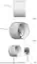
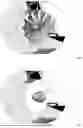
FIG. 1a: Corresponds to the total view of the Current Energy Collection Unit (1) in the operation arrangement, in a frontal view.
FIG. 1b: Corresponds to the total view of the Current Energy Collection Unit (1) in the operation arrangement, in rear view.
FIG. 1c: Corresponds to the total view of the Current Energy Collection Unit (1) in the operation arrangement, in side view.
FIG. 1d: Corresponds to the total view of the Current Energy Collection Unit (1) in the operation arrangement, in perspective.
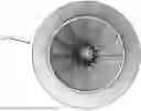
FIG. 2: relates to the Current Energy Collection Unit (1), highlighted the turbine (2) and the casing (3).
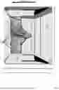
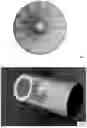
FIG. 3: illustrates the longitudinal section, in relation to the sense of the flow, the casing (3), in which the component compartments of the horizontal control volume are highlighted, namely: load (6), work (7), and discharge (8); and the free compartment (9) through which there is no flow. The work compartment (7) comprises the turbine (2) composed of blade (4) and an axle in the form of an elliptical cap (5).
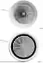
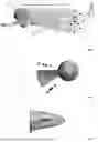
FIG. 4: Shows the segment of the casing in perspective (3) with the complete turbine (2) to be compared with FIG. 5.
FIG. 5: Shows the segment of the casing in perspective (3) with the part of the turbine corresponding to the axle (5), with a view to reducing the cross-sectional area to the current direction.
FIG. 6: In an orthogonal front view, the obstacle zone is indicated, without any gaps, positioned by the turbine to the flow lines, configured by the number, shape and arrangement of the blades with the axle, i.e., the total opacity through the current, such as an essential condition for capturing the energy associated with the Current Structures.
FIG. 7: Illustrates, in perspective, the opacity of the turbine, using the concept of parallel rays of light that are analogous to the flow lines. The volume of the light represents the control volume.
FIG. 8: Merely conceptual, highlights the volume of control (10) of said flow machine (1) in an installation condition, that is, it relates to the concept of the structure or water block in the upstream current which kinetic energy is associated, and that is renewable by the action of incident forces of the nature at a planetary magnitude, to be converted into electricity before the densely opaque circular area, perpendicular to the natural direction of the flow lines (11), formed by the front perspective of the invention as FIG. 1a.
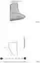
FIG. 9: Shows the frontal view of a single blade (4) with the angle (θ) of coverage thereof, fixed to the axle (5), and projecting on line and point the cutting arc A-B as reference to the scheme shown in FIG. 12.
FIG. 10: Highlighted in side view the profile of a single blade (4) fixed to the axle (5).
FIG. 11: Highlight in lateral view of the surface of a single blade (4), attached to the axle (5).
FIG. 12: Flat layout of the axial profile of the blades (4) referenced in FIG. 9 as cutting A-B, whatever the radial position.
DESCRIPTION OF THE INVENTION
As can be inferred from the drawings that accompany and form part of this specification, the Current Energy Collector Unit is characterized by being made up of a reaction turbine (2), positioned in the work compartment (7) of the enveloping structure (3).
Constituted by an axle and blades which project the integrity of the circular area parallel to the cross-sectional plane with the current, the turbine (2) is a submerged rotary machine, activated by the consequent force of the ratio between the variation in the amount of movement of the upstream current (10) and the transit time of the fluid particles through the working compartment, and transferring the collected mechanical energy in the process to electrical submerged generators or on platforms on the surface water.
The sense of rotation is unique in order to guarantee the maximum efficiency of energy capture, to be defined in the design of each unit, but must be exclusively clockwise or exclusively anti-clockwise, and is inefficient in reversibility.
The axle (5), of which is an elliptical cap geometry, has the smooth surface support the blades (4) while it receiving from each the torque contribution.
The blades (4) complete the projection of the entire shock zone, i.e., the circular area of the turbine with diameter dt parallel to the plane of the cross-section of the current, wherein the number of blades is the ratio between the circumference and the arch (θ) of each blade (FIG. 9), according to the equation:
θ = 3 6 0 ∘ n
Where n is the number of blades and n∈
This feature causes each particle of the seawater that is transported in the current to deflect its path to the direction tangential to the axis, urging the blade reaction in the opposite sense.
The axial profile of the blades is an ellipse arc of 90° (FIG. 12). r1 and r2 radius vary in accordance with the radial position, the r1 increases regularly from the axis to the edge of the turbine. In turn, the r2 radius, on the contrary, decreases from r2 max, on the axis, to r2 min to 50% of the radial line towards the edge of the turbine (FIG. 11), in a curve determined by the mechanical strength of the constituent materials of the individual parts and connections of the turbine.
The blades, such as knifes, have the thickness determined by the mechanical strength of the constituent materials, between internal structure and surface, varying according to the effort required.
The turbine has a casing as an accessory that, under the scientific branch of mechanics of continuous environment, meets the principle of conservation of energy, as stated by the Swiss mathematician Daniel Bernoulli. It is a cylindrical tube with diameter dc and extension ee, the inner side of which tapers to an angle α in the load compartment (6), reducing diameter dc through reduction extension er to working diameter dτ. The working compartment (7) shelters the turbine (2), has the extension eτ. The free compartment (9) is the inner region of the envelope where there is no flow, it imposes a reduction in the diameter of the loading compartment for the work compartment. The discharge compartment (8) it paths the flow that has already performed the work to the discharge itself, returning it to the current.
The Current Energy Collection Unit is fully scalable:
-
- For meeting the individual electrical power goals or the nominal electric power of standardized generators;
- In attention to oceanographic reports pertinent to the installation sites;
- In attention to the mechanical strength of the constituent materials.;
The dimensions are free, as long as they reach the following rules:
-
- The input diameter of the load compartment (6) is greater than the diameter of the work compartment (7):
dc>dτ
-
- The reduction extension is a function between the reduction angle and the input diameter of the load compartment (6):
er = ( dc - d τ ) tan α 2
-
- The diameter of the work compartment (6) is slightly larger than the diameter of the turbine (2), just enough that the turbine can freely rotate without touching the casing (3):
dτ>dt
Conclusion
The invention relates to an energy collection unit that has been described and illustrated to be a Current Energy Collection Unit, which fits perfectly in the standards governing the patent of invention, and should fill an important gap in the market, deserving for what has been exposed and as a consequence, the respective privilege.
Claims
1. Current Energy Collector Unit (1), characterized by being constituted by a reaction turbine (2) associated with a tubular enveloping structure with a trapezoid wall (3), so as to form a densely opaque circular area perpendicular to the natural direction of the flow lines (11) and, therefore, capable of causing a variation in the momentum of the entire upstream water mass (10) in the volume of these lines, absorbing the energy from the process.
2. Current Energy Collector Unit (1), according to claim 1, characterized by a reaction turbine (2) in which its axis (5) and the blades (4) form a collision area that covers the entirety of the turbine's projection in the cross-sectional flow.
3. Current Energy Collector Unit (1), according to claim 2, characterized by a reaction turbine (2) with blades (4) in which the axial profile is a 90° elliptical arc with radii varying according to the radial position, with r1 increasing and r2 decreasing from the axis to the edge.
4. Current Energy Collector Unit (1), according to claim 2, characterized by a reaction turbine (2) in which the axis (5) has the geometric shape of an elliptical cap, its cross-sectional area increasing in the direction of the current, being smaller in the loading area and larger in the discharge area.
5. Current Energy Collector Unit (1), according to claim 1, characterized by a tubular enveloping structure, which houses the turbine (2) in the working compartment (7), receives the flow in the loading compartment (6) and discharges it in the discharge compartment (8), so that the cross-sectional flow area is reduced in transit through the loading compartment (6) to the diameter of the working compartment (7) through the occupation by the volume of the free compartment (9).
Images & Drawings included:
Sources:
- United States Patent and Trademark Office - verify current appl. status at the USPTO↗
Recent applications in this class:
- » 20250283447 2025-09-11
TIDAL POWER GENERATION SYSTEM. - » 20250137431 2025-05-01
SUBMERSIBLE BOX-WINGED VEHICLE SYSTEMS AND METHODS FOR GENERATING HYDROELECTRIC ENERGY - » 20250092851 2025-03-20
SYSTEMS AND METHODS FOR POWER DISTRIBUTION AND HARNESSING OF MARINE HYDROKINETIC ENERGY - » 20240254957 2024-08-01
SUCTION COVER DEVICE, AND KINETIC TIDAL POWER PLANT - » 20240209828 2024-06-27
Tidal stream generation apparatus - » 20230151791 2023-05-18
Renewable energy generation system and control method therefor - » 20220403814 2022-12-22
Systems and methods for power distribution and harnessing of marine hydrokinetic energy - » 20220243698 2022-08-04
Tidal power generation device and container assembly for accommodating power generation device - » 20210207571 2021-07-08
TIDAL POWER GENERATING SYSTEM - » 20210148326 2021-05-20
Tide Activated Device to Operate A Turbine Generator