PADDLEBOARD-PICNIC PLATFORM
US20240367758A1
2024-11-07
18/654,649
2024-05-03
Smart Summary: A picnic platform can be attached between two paddleboards or surfboards, allowing people to enjoy meals while on the water. It has edges designed to connect to the boards using magnets, hook-and-loop strips, or elastic bands. The top surface of the platform can also have special spots to hold plates, cups, and utensils securely. This makes it easy to have a picnic without worrying about items falling into the water. Overall, it combines fun on the water with dining convenience. 🚀 TL;DR
Abstract:
A picnic platform is configured to removably couple between two parallel paddleboards or surfboards for dining while out on the water. In some examples, the platform defines opposing outer edges configured to couple to the paddleboards via magnets, hook-and-loop strips, elastic bands, or any other suitable attachment mechanism. Similar types of attachment mechanisms can be embedded throughout a top surface of the platform to retain dining instruments such as plates, cups, and utensils.
Applicant:
Interested in similar patents?
Get notified when new applications in this technology area are published.
Classification:
B63B32/77 » CPC main
Water sports boards; Accessories therefor Arrangements for fixation of accessories to the board, e.g. inserts or rails
B63B32/40 » CPC further
Water sports boards; Accessories therefor Twintip boards; Wakeboards; Surfboards; Windsurfing boards; Paddle boards, e.g. SUP boards; Accessories specially adapted therefor
Description
RELATED APPLICATION
This application claims the benefit of U.S. Provisional Application No. 63/464,132 filed May 4, 2023, which is hereby fully incorporated herein by reference.
TECHNICAL FIELD
The present technology is generally related to watersports.
BACKGROUND
Stand-up paddleboarding has grown immensely popular in recent years. A typical paddleboard is a buoyant, yet relatively heavy elongated board, thus defining a very low center of gravity to counteract the high center of gravity of a rider standing thereupon. Accompanying the heavy board is an elongated paddle, often substantially longer than a canoeing oar to account for the height of the rider above the water.
SUMMARY OF THE DISCLOSURE
In general, the present disclosure relates to accessories that enable a pair of paddleboarders to enjoy a floating, open-water picnic. In particular, the accessories include a substantially planar platform configured to removably couple between two parallel paddleboards, such that the assembled system functions as a buoyant picnic table.
In some examples, the platform includes a suitable removable-attachment mechanism that enables the platform to couple to existing paddleboard models, e.g., wherein the platform can be “retrofitted” without requiring modification of the boards. Additionally or alternatively, customized paddleboards can be embedded with counterpart coupling mechanisms, such as magnets or mechanical couplings, at the time of manufacture.
Other objects, advantages, features, properties and relationships of the invention will be obtained from the following detailed description and accompanying drawings which set forth illustrative embodiments that are indicative of the various ways in which the principles of the invention may be employed.
BRIEF DESCRIPTION OF THE DRAWINGS
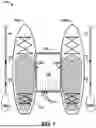
FIG. 1 is an overhead view of an example paddleboard-picnic system that includes a platform coupled between two parallel paddleboards.
FIG. 2 is a close-up view of an example of the platform of FIG. 1, including a plurality of embedded magnets to couple to the paddleboards.
FIG. 3 is a close-up view of another example of the platform of FIG. 1, including a pair of coupling flaps extending laterally outward therefrom.
FIG. 4 is a close-up view of another example of the platform of FIG. 1, having a substantially rectangular-shaped dining surface.
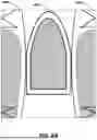
FIG. 5 is a close-up view of another example of the platform of FIG. 1, having an irregular geometric shape that defines a pair of leg apertures to facilitate sitting on the paddleboards.
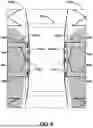
FIG. 6 is a close-up view of an example “brassiere type” removable-coupling mechanism for the paddleboard-picnic system of FIG. 1.
FIG. 7 is a close-up view of another example of the platform of FIG. 1, including an elastic-band-type removable-coupling mechanism.
FIG. 8A is a close-up view of another example of the platform of FIG. 1, having a shape that substantially mirrors the front nose portions of the paddleboards.
FIG. 8B is an overhead view of the platform of FIG. 8A stored within a front compartment of the paddleboard.
FIG. 8C is a side view of the platform of FIGS. 8A and 8B coupled atop a vertical mount toward the front of the paddleboard.
DETAILED DESCRIPTION
The present disclosure describes exemplary systems, devices, and techniques enabling a pair of paddleboarders to enjoy a floating, open-water picnic. In particular, the accessories include a substantially planar platform configured to removably couple between two parallel paddleboards, such that the assembled system functions as a buoyant picnic table. While the term “paddleboard” is recited throughout this disclosure, it is to be understood that paddleboards, surfboards, and windsurfing boards are considered functional equivalents for the purposes described herein, and may be referenced interchangeably.
Certain systems have previously been devised for fusing multiple waterboards together, however, none of these systems are configured for facilitating a waterborne dining experience. For instance, United Kingdom Patent Application No. GB8,316,906 (Publication No. GB2,124,157) by Jens Peter Jensen describes a “rack structure” for merging two surfboards and a sail into one large “catamaran vessel.” However, the “rack system” is merely an “open” structural frame that would not be suitable for supporting a set of dining instruments (e.g., plates, cups, utensils, etc.).
International Patent Application Number PCT/US91/03917 (Publication No. WO1992/021556) by Steven D. Winter et al. describes a device for merging two windsurfing boards into one large “wind sailing surf vessel.” The two boards are held together via an “arching platform” that extends across most of the top surfaces of both boards. The substantially curved upper surface of the arching platform would not be suitable for retaining dining instruments, which would readily roll off into the water.
Finally, U.S. Pat. No. 7,182,037 to Taiichi Otobe et al. describes a “frame structure” for coupling a “propulsion unit” (e.g., an outboard motor) between two surfboards. Similar to Jensen, above, the frame structure is merely a hollow “skeleton structure formed of plural pipe members coupled together, and accordingly, would not be suitable for dining.
By contrast, examples of the present disclosure include structurally rigid platforms each defining a substantially flat, table-like top surface for placing dining instruments. As detailed further below, the platforms can include additional features uniquely tailored for removably retaining dining instruments while freely floating on the surface of the water. Additionally, unlike in the documents referenced above, examples of the present disclosure are configured to couple between two paddleboards in a way that leaves most or all of the top surfaces of the boards available for sitting down to enjoy a picnic.
For instance, FIG. 1 is an overhead view of an example paddleboard-picnic system 100, in accordance with the techniques of this disclosure. As shown in FIG. 1, system 100 includes a substantially planar picnic platform 102, a first paddleboard 104A, a second paddleboard 104B (collectively, “boards 104”), and their accompanying elongated paddles 140A, 140B. Platform 102 defines a planar dining surface 106, and two outer edges 108A, 108B positioned on opposite sides of dining surface 106. First outer edge 108A (or a bottom portion thereof) is configured to removably couple to first paddleboard 104A, and second outer edge 108B (or a bottom portion thereof) is configured to removably couple to second paddleboard 108B, while the two paddleboards 104A, 104B are oriented substantially parallel to one another.
Picnic platform 102 can define any suitable spatial dimensions. As a few non-limiting examples, a vertical thickness of platform 102 (e.g., directed into the page, from the perspective of FIG. 1) can be less than, more than, or approximately the same as the typical vertical thickness of paddleboards 104, e.g., at least about 0.25 inches, at least about 0.5 inches, at least about 0.75 inches, at least about 1 inch or at least about 2 inches in thickness, and up to about 7 inches, up to about 6 inches, up to about 5 inches or up to about 4 inches in thickness. Picnic platform 102 can define a bow-to-aft length (e.g., from the top to the bottom of the page, from the perspective of FIG. 1) that ranges from about ⅛ or from about ¼ of the length of paddleboards 104, up to about ¾ or up to about ½ of the length of paddleboards 104. In some examples, a port-to-starboard width (e.g., left-to-right, from the perspective of FIG. 1) of platform 102 can range from about ¼ or from about ½ of the width of either of paddleboards 104, up to about ¾ or up to about the same width as either of paddleboards 104. For general context, typical paddleboards average about 10 to 11 feet long, and about 30 to 36 inches wide.
The present disclosure illustrates various example attachment mechanisms that may be used to couple platform 102 to boards 104, as well as various shapes and sizes of platform 102. It is to be understood that none of these features are intended to be mutually exclusive, except where explicitly noted herein—any of the example features and configurations described herein may be used or otherwise incorporated simultaneously.
In the example illustrated in FIG. 1, opposing outer edges 108A, 108B are depicted as being slightly curvilinear, to generally conform to the counterpart curvatures along paddleboards 104 where platform edges 108 are configured to attach. In addition, outer edges 108 of platform 102 are depicted in FIG. 1 as marginally overlapping with boards 104, or in other words, platform 102 couples to boards 104 in a way that causes platform 102 to partially extend overtop of boards 104. In some such examples, in which platform 102 defines a substantially rectangular cross-sectional area (e.g., the cross-section being taken perpendicular to dining surface 106), a bottom surface of platform 102 would be configured to extend partially over the top surfaces of boards 104, such that the bottom surface of platform 102 “hovers” above the surface of the water. In other examples, platform 102 can define irregular cross-sectional shapes wherein an upper portion of platform 102 extends partially overtop of boards 104, while a lower portion of platform 102 can conform to the curved inner edges of boards 104 and extend downward into the water. In other words, platform 102 can be substantially aligned with boards 104 relative to the surface of the water.
Picnic system 100 is configured to be highly convenient and portable. As one example, part or all of platform 102 can be an inflatable device that, when deflated, can be rolled up and stowed under elastic cords 110. Additionally, or alternatively, part or all of picnic platform 102 can be formed from a plurality of elongated foam slats 112 coupled along their collective top surface 106 (or bottom surface) by a flexible sheet of fabric or other material (e.g., conceptually similar to certain exercise and yoga mats). In such examples, when not in use, platform 102 can be rolled up and stowed for transport, e.g., underneath elastic cords 110. In other examples, platform 102 can be formed as a single, integrated structure, such as a sheet of waterproof foam or wood.
FIG. 2 is a close-up view of a paddleboard picnic platform 202, which is an example of platform 102 of FIG. 1, apart from any distinctions explicitly noted herein. As with FIG. 1, opposing outer edges 108 are coupled to boards 104 such that edges 108 at least partially extend over the top surfaces of boards 104. In particular, a bottom surface of platform 202 includes a plurality of embedded magnets 214 distributed along outer edges 108. Magnets 214 are configured to magnetically attract a series of counterpart magnets embedded within the top surfaces of boards 104 to retain platform 202 in place relative to boards 104 while in use for dining. In some examples, the counterpart magnets can be integrally embedded within the top surfaces of boards 104, e.g., at the time of manufacture. In other examples, the counterpart magnets can be distributed as part of a customization “kit” along with platform 202, wherein the user is encouraged to manually adhere (e.g., “retrofit”) the magnets to the top surfaces of boards 104.
In addition to, or instead of, magnets 214, the bottom surface of platform 202 can include a different removable coupling mechanism, such as strips of hook-and-loop-type fabric (widely known by the brand name Velcro®), or any other functional equivalent. In addition to being distributed along opposing edges 108, any or all of these types of removable coupling mechanisms can also be embedded throughout top dining surface 106 of platform 202 to retain certain dining equipment, e.g., in choppy waters. For instance, as illustrated in FIG. 2, top dining surface 106 is embedded with various removable couplers (e.g., magnets, etc.) 216-224. Removable couplers 216-224 are both sized and shaped to removably retain specific dining instruments (not shown) that themselves include counterpart removable couplers, e.g., embedded therein. For instance, removable couplers 216A, 216B are configured to help retain dining plates on top dining surface 106. Similarly, removable coupler(s) 218 are configured to retain drinking cups, removable coupler(s) 220 are configured to retain utensils, removable coupler(s) 222A, 222B are configured to retain coolers or other storage bags, and removable coupler(s) 224A, 224B are configured to retain larger, communal serving dishes.
Additionally, or alternatively to having designated removable couplers 216-224, in some examples, the entirety of top dining surface can be formed from a removable coupler, such as a large sheet of hook-and-loop fabric. As another example, dining surface 106 can include a rectangular sheet 226 of embedded metal configured to retain counterpart magnets embedded within associated dining instruments. Additionally, or alternatively, top surface 106 can define physical ridges and grooves (e.g., cupholders), configured to help retain various dining instruments in place.
In some examples, additional removable couplers 240A, 240B can be embedded within boards 104, platform 202, or both, wherein removable couplers 240 are configured to retain elongated paddles 140A, 140B (as depicted in FIG. 1). For instance, removable couplers 240 can magnetically attract metal portions of paddles 140 (e.g., central elongated metal shafts 144) or counterpart magnets 142 embedded within paddles 140. Additionally, or alternatively, couplers 240 can include: physical features (e.g., ridges and grooves) defined by dining surface 106, plastic clips, or any other suitable paddle-retention mechanism.
Additionally, or alternatively, paddles 140 of FIG. 1 can be configured to removably couple to magnets 214 embedded within platform 202, or the counterpart magnets embedded within boards 104, for safe-keeping while dining. For instance, paddles 140 can include an embedded set of counterpart magnets 142 spaced and oriented to align with magnets 214. In some examples, a metal material of the shafts 144 of paddles 140 can magnetically couple to magnets 214 embedded within platform 202 or the counterpart magnets embedded within boards 104. In some examples, boards 104 can include an additional set of magnets (not shown) embedded along the outer edges, e.g., opposite from platform 202, configured to magnetically retain paddles 140.
FIG. 3 is a close-up view of a paddleboard picnic platform 302, which is an example of platform 102 of FIG. 1 and platform 202 of FIG. 2, apart from any distinctions explicitly noted herein. For instance, unlike with platforms 102 and 202, opposing outer edges 108 of platform 302 do not extend over the top surface of paddleboards 104. Instead, opposing outer edges 108 of platform 302 abut the edges of paddleboards 104 such that dining surface 106 is substantially level with the top surfaces of paddleboards 104.
Accordingly, instead of platform 302 having removable couplers embedded in its bottom surface, platform 302 includes a pair of coupling flaps 328A, 328B that extend outward from dining surface 106 and onto the top surfaces of paddleboards 104. Coupling flaps 328 can include any suitable removable coupling mechanism described throughout this disclosure, such as elongated strips of hook-and-loop fabric, embedded magnets, or any functional equivalent.
FIG. 4 is a close-up view of a paddleboard picnic platform 402, which is an example of platforms 102, 202, and 302, apart from any distinctions explicitly noted herein. For instance, unlike with platforms 102-302, which define curvilinear outer edges 108, platform 402 defines substantially straight outer edges 408A, 408B, such that platform 402 defines a substantially rectangular shape overall. Additionally, while FIG. 4 is depicted as including coupling flaps 328, it is to be understood that in other examples, platform 402 can be configured to couple to the top surfaces of boards 104 via its bottom surface, similar to the examples shown in FIGS. 1 and 2. FIG. 4 is merely intended to illustrate the wide variety of geometric shapes that may be used for picnic platforms of system 100 (FIG. 1).
FIG. 5 is a close-up view of a paddleboard picnic platform 502, which is an example of platforms 102, 202, 302, and 402, apart from any distinctions explicitly noted herein. Specifically, FIG. 5 illustrates another example geometric shape for a picnic platform of system 100 (FIG. 1), in the form of an hourglass-type shape. That is, curvilinear outer edges 508A, 508B deviate substantially from the curvature of paddleboards 104 to define central gaps or apertures 530A, 530B between platform 502 and paddleboards 104. Apertures 530 are designed (e.g., sized and shaped) to receive the lower legs of the users while the users are sitting down on the top surfaces of their respective paddleboards, such that the users' feet are dangling down into the water. Such configurations may present a more-comfortable sitting arrangement than other examples, in which the users could either sit either cross-legged, or wide-legged (e.g., straddling the platform entirely).
FIG. 6 is a close-up view of an example of picnic system 100 of FIG. 1 that includes a pair of brassiere-type removable-coupling mechanisms 632A, 632B (collectively, “couplers 632”). Couplers 632 represent an example removable-coupling mechanism that is physically separable from both paddleboards 104 as well as picnic platform 602. To achieve this bi-directional separability, removable couplers 632 integrate multiple different types of coupling mechanisms. First, each coupler 632A, 632B includes an elastic fabric band 634A, 634B having one or more elongated straps that stretch or wrap around the respective paddleboard 104. As shown in FIG. 6, the individual fabric straps can each include a length-adjustment clasp 636 enabling the user to tighten or loosen the straps around paddleboards 104 as needed, e.g., to accommodate different-sized paddleboards.
A top surface of couplers 632 can include a plurality of embedded magnets 614 (or the functional equivalent) configured to magnetically couple to counterpart magnets (e.g., magnets 214 of FIG. 2) embedded within a bottom surface of platform 602 (or within coupling flaps of platform 602, if present).
Similar to the example described above with respect to FIG. 2, paddles 140 of FIG. 1 can also be configured to removably couple to any or all of platform 602, removable couplers 632 and paddleboards 104. For instance, the elongated shafts 144 of paddles 140 can have a set of embedded magnets 142 spaced and oriented to align with brassiere magnets 614 or the counterpart magnets (e.g., magnets 214 of FIG. 2) embedded within the bottom surface of platform 602. Additionally or alternatively, designated “paddle” magnets 642 embedded within the fabric straps of couplers 632 can magnetically retain counterpart magnets 142 within paddles 140 or metallic shafts 144 of paddles 140.
In some examples, removable couplers 632 can include elongated strips or loops of “waterproof indoor/outdoor acrylic adhesive magnet tape.” For instance, strips of magnetic tape may be used either in conjunction with, or instead of, fabric straps embedded with discrete magnetic features.
FIG. 7 illustrates another example removable coupling mechanism 732A, 732B (collectively, “couplers 732”) that may be used to removably couple picnic platform 702 between paddleboards 104. Each coupler 732 includes an elastic fabric or rubber band defining three distinct (but inseparable) loops: a “first” loop 738A configured to stretch around paddleboard 104A, a “second” loop 738B configured to stretch around picnic platform 702, and a “third” loop 738C configured to stretch around paddleboard 104B. In examples, couplers 732 can be formed with an additional length of fabric between adjacent loops 738A/738B and 738B/738C so as to define leg apertures 530A, 530B, similar to the example shown in FIG. 5.
FIGS. 8A-8C illustrate a substantially rigid, or “solid core” paddleboard-picnic platform 802, which can be an example of any or all of the picnic platforms described above, apart from any distinctions explicitly noted herein. Specifically, FIG. 8A illustrates another example geometric shape for a picnic platform of system 100 (FIG. 1), in which the outer perimeter of platform 802 substantially conforms to the outer profile of the front “nose” or “bow” of paddleboards 104A, 104B. This shape may be referred to as a “kickboard” shape reminiscent of smaller, buoyant boards often used to help teach beginners how to swim.
For instance, as shown in FIG. 8B, the top surface near the front nose or bow of paddleboard 840 can define a recessed compartment 846 that similarly conforms to the tapered forward profile of the board. Compartment 846 is sized and shaped to receive and retain picnic platform 802 such that top dining surface 106 of platform 802 is level or “flush” with the top surface of paddleboard 804 while platform 802 is held therein. The perimeter or inner surfaces of compartment 846 can include appropriate removable-coupling features, such as magnets, to hold platform 802 in place until manually removed by a user.
FIG. 8C is a side view of an example of paddleboard 804 and picnic platform 802 of FIG. 8B. In the example depicted in FIG. 8C, platform 802 is vertically retractable down into, and extendable up out of, recessed storage compartment 846. Specifically, paddleboard 804 includes a vertical mount 848 coupled within storage compartment 846, wherein picnic platform 802 is configured to removably couple to the top of vertical mount 848. In this way, platform 802 may be either (1) removably coupled between two paddleboards (as with the examples described above), or (2) extended upward to provide a raised platform directly above paddleboard 804 for a “solo” dining experience.
Vertical mount 848 is depicted in FIG. 8C as a telescoping mechanism (e.g., similar to those implemented in certain office chairs), enabling the user to adjust mount 848 to a desired height. Any other suitable type of “collapsible” or “retractable” mount may be used, such as a kickstand-like (e.g., “swiveling”) mount. While in the “extended” configuration shown in FIG. 8C, the combination paddleboard-platform defines two vertical levels of storage: on top of dining surface 106, and within storage compartment 846 underneath platform 802.
While specific embodiments of the invention have been described in detail, it will be appreciated by those skilled in the art that various modifications and alternatives to those details could be developed in light of the overall teachings of the disclosure. Accordingly, the particular arrangements disclosed are meant to be illustrative only and not limiting as to the scope of the invention, which is to be given the full breadth of the appended claims and any functional equivalents thereof.
Claims
What is claimed is:1. A paddleboard-picnic platform comprising:
a substantially planar top surface configured to retain a set of dining instruments;
a first outer edge configured to removably couple to a first paddleboard; and
a second outer edge configured to removably couple to a second paddleboard while the second paddleboard is oriented substantially parallel to the first paddleboard, wherein the first outer edge and the second outer edge define opposite sides of the top surface of the platform.
2. The paddleboard-picnic platform of claim 1, further comprising a plurality of elongated slats collectively coupled by a flexible sheet of material such that the platform is rollable for storage and transport, wherein the flexible sheet of material is coupled across a collective surface of the plurality of elongated slats.
3. The paddleboard-picnic platform of claim 1, wherein a bottom surface of the platform comprises a first coupling mechanism disposed along the first outer edge and the second outer edge, wherein the first coupling mechanism is configured to magnetically couple to a second coupling mechanism rigidly coupled to the first paddleboard and the second paddleboard.
4. The paddleboard-picnic platform of claim 1, wherein the top surface of the platform comprises an embedded sheet of metal configured to magnetically couple to magnets embedded in the set of dining instruments.
5. The paddleboard-picnic platform of claim 1, wherein the first outer edge of the platform comprises a first coupling flap configured to removably couple to the first paddleboard, and wherein the second outer edge of the platform comprises a second coupling flap configured to removably couple to the second paddleboard.
6. The paddleboard-picnic platform of claim 5, wherein the first coupling flap and the second coupling flap comprise strips of hook-and-loop fasteners.
7. The paddleboard-picnic platform of claim 1, wherein the first outer edge and the second outer edge are curvilinear to conform to curvatures of the first paddleboard and the second paddleboard.
8. A system comprising:
a first paddleboard;
a second paddleboard; and
a platform comprising:
a substantially planar top surface configured to retain a set of dining instruments;
a first outer edge configured to removably couple to the first paddleboard; and
a second outer edge configured to removably couple to the second paddleboard while the second paddleboard is oriented substantially parallel to the first paddleboard.
9. The system of claim 8, further comprising the set of dining instruments, wherein each of the set of dining instruments is removably coupled to the top surface of the platform via one or more couplers embedded in the top surface.
10. The system of claim 8, wherein the top surface of the platform comprises a plurality of magnets each configured to magnetically couple to a respective embedded magnet of one of the set of dining instruments.
11. The system of claim 8, wherein the top surface of the platform comprises an embedded sheet of metal configured to magnetically couple to magnets embedded in the set of dining instruments.
12. The system of claim 8, wherein the platform comprises a plurality of elongated slats collectively coupled by a flexible sheet of material, such that the platform is rollable for storage and transport, wherein the flexible material is coupled across a collective surface of the plurality of elongated slats.
13. The system of claim 8, wherein a bottom surface of the platform comprises a first plurality of magnets disposed along the first outer edge and the second outer edge, wherein the first plurality of magnets is configured to magnetically couple to a second plurality of magnets rigidly coupled to the first paddleboard and the second paddleboard.
14. The system of claim 8, wherein the first outer edge of the platform comprises a first coupling flap configured to removably couple to the first paddleboard, and wherein the second outer edge of the platform comprises a second coupling flap configured to removably couple to the second paddleboard.
15. The system of claim 14, wherein the first coupling flap and the second coupling flap comprise strips of hook-and-loop fasteners.
16. The system of claim 8, wherein the first outer edge and the second outer edge are curvilinear to conform to curvatures of the first paddleboard and the second paddleboard.
17. The system of claim 8, further comprising a pair of coupling bands that are removably coupled to the first paddleboard, the platform, and the second paddleboard, wherein each of the pair of coupling bands comprises:
a fabric loop configured to stretch around the first paddleboard or the second paddleboard; and
a plurality of magnets embedded in the fabric loop, wherein the plurality of magnets are configured to magnetically couple to counterpart magnets embedded in the platform.
18. The system of claim 8, wherein a front portion of the first paddleboard or the second paddleboard defines a recessed compartment configured to receive and retain the platform.
19. The system of claim 8, wherein the first paddleboard or the second paddleboard comprises a vertical mount configured to extend the platform vertically above the first paddleboard or the second paddleboard.
20. A paddleboard-picnic platform comprising:
a substantially planar top surface configured to retain a set of dining instruments;
a first outer edge configured to removably couple to a first paddleboard; and
a second outer edge configured to removably couple to a second paddleboard while the second paddleboard is oriented substantially parallel to the first paddleboard, wherein the first outer edge and the second outer edge define opposite sides of the top surface of the platform,
wherein a bottom surface of the platform comprises a first coupling mechanism disposed along the first outer edge and the second outer edge, wherein the first coupling mechanism is configured to couple to a second coupling mechanism rigidly coupled to the first paddleboard and the second paddleboard, and
wherein the top surface of the platform comprises an embedded sheet of metal configured to magnetically couple to magnets embedded in the set of dining instruments.
Images & Drawings included:


Sources:
- United States Patent and Trademark Office - verify current appl. status at the USPTO↗
Recent applications in this class:
- » 20240317365 2024-09-26
SEMI-FLEXIBLE INSTRUMENTATION MOUNT - » 20230382501 2023-11-30
Adjustable cord locking arrangement - » 20210129947 2021-05-06
Waterboard - » 20200407028 2020-12-31
Mounting apparatus and related methods of fabricating or retrofitting a surfboard with said mounting apparatus - » 20200148312 2020-05-14
Aquatic board saddle - » 20110162172 2011-07-07
FASTENER FOR WATER-SPORT APPLIANCE - » 20060148345 2006-07-06
Surfboard drain and leash plug