WIRELESS ATOMIZER
US20250089784A1
2025-03-20
18/886,744
2024-09-16
Smart Summary: A device is designed to turn liquid into vapor that can be inhaled. It has a chamber where the vaporization happens, positioned between a mouthpiece and a battery. Inside this chamber, there is a special ceramic material that touches the liquid. A filament connects to this ceramic, with both ends exposed to help create the vapor. When the device is used, electricity flows through the filament, heating it up to produce the vapor. 🚀 TL;DR
Abstract:
A vaporizing apparatus for converting a liquid into an inhalable vapor. A conduit having a vaporization chamber, is located between a mouthpiece and a battery module. The vaporization chamber includes porous ceramic that is in contact with the liquid. A filament has a first end and a second end where the first end and second end are exposed on the ceramic. A first electrode and a second electrode have compression contacts with the first end and the second end respectively to allow a current to flow through the filament during normal operation.
Assignee:
- Bold Crafts, LLC 1 🇺🇸 Tempe, AZ, United States
Applicant:
Interested in similar patents?
Get notified when new applications in this technology area are published.
Classification:
A24F40/46 » CPC main
Electrically operated smoking devices; Component parts thereof; Manufacture thereof; Maintenance or testing thereof; Charging means specially adapted therefor; Constructional details, e.g. connection of cartridges and battery parts Shape or structure of electric heating means
A24F40/10 » CPC further
Electrically operated smoking devices; Component parts thereof; Manufacture thereof; Maintenance or testing thereof; Charging means specially adapted therefor Devices using liquid inhalable precursors
A24F40/44 » CPC further
Electrically operated smoking devices; Component parts thereof; Manufacture thereof; Maintenance or testing thereof; Charging means specially adapted therefor; Constructional details, e.g. connection of cartridges and battery parts Wicks
Description
PRIORITY
This application is a non-provisional and claims the priority benefit of U.S. Provisional Application No. 63/582,793, filed Sep. 14, 2023, and U.S. Provisional Application No. 63/583,837, filed Sep. 19, 2023, the disclosures of each of which are hereby incorporated by reference in their entirety for all purposes.
BACKGROUND
This disclosure relates in general to an electronic circuit of an atomizer and, but not by way of limitation, to an arrangement of different components of a vaping apparatus for atomization amongst other things.
In the field of electronic aerosolizing and misting devices, vaporizing has gained significant popularity as an alternative to traditional smoking, offering a potentially reduced-risk alternative for individuals seeking nicotine delivery, for example. Current vaping devices generally consist of a battery, a heating element, and a reservoir for holding e-liquid or vape juice. Manufacture of the components and assembly of the vaping devices is complex and labor intensive. Complex assemblies can be prone to maintenance and reliability problems.
SUMMARY
In one embodiment, a vaporizing apparatus converts a liquid into an inhalable vapor, comprising a suction pipe fluidly coupled to a mouthpiece. A battery module is installed away from the mouthpiece. A conduit having a vaporization chamber, is located between the mouthpiece and the battery module. The vaporization chamber is enclosed with porous ceramic that is in contact with the liquid. A filament, formed in a helical winding, has a first end and a second end where the first end is exposed on the top of the ceramic, and the second end is exposed on the bottom of the ceramic. The filament is at least partially embedded into the ceramic. A first electrode and a second electrode have compression contacts with the first end and the second end respectively to allow a current to flow through the filament during normal operation. The filament heats the liquid to change its state to the inhalable vapor.
In another embodiment, a vaporizing apparatus converts a liquid into an inhalable vapor. The vaporizing apparatus includes a mouthpiece, a batter module, a tank having a cavity, and a ceramic element. The vaporizing apparatus further includes a filament, a first electrode, and a second electrode. The mouthpiece is coupled to a conduit and the battery module is configured away from the mouthpiece. In the cavity, the conduit is located between the mouthpiece and the battery module of the vaporizing apparatus. The ceramic element is fluidly coupled with the cavity, and includes a top, a bottom and a vaporization chamber. The vaporization chamber is fluidly coupled with the conduit that extends from the top to the bottom. The vaporization chamber has a length and an inner diameter. The filament is formed in a helical winding having an outer diameter and a height and the outer diameter is equal to or greater than the inner diameter. The height of the filament is greater than or equal to the length of the vaporization chamber. The filament has a first end and a second end, where the first end is exposed on the top, and the second end is exposed on the bottom. The first electrode has compression contact with the first end to allow a current to flow during normal operation, and the second electrode has compression contact with the second end to allow the current to flow during normal operation. The filament heats the liquid to change its state to the inhalable vapor using the current, and suction at the mouthpiece evacuates the inhalable vapor toward the mouthpiece.
In still embodiment, an electronic vaporizer converts a liquid into an inhalable vapor. The electronic vaporizer includes a mouthpiece, a batter module, a tank having a cavity, and a ceramic element. The electronic vaporizer further includes a filament, a first electrode, and a second electrode. The mouthpiece is coupled to a conduit and the battery module is configured away from the mouthpiece. In the cavity, the conduit is located between the mouthpiece and the battery module of the electronic vaporizer. The ceramic element is fluidly coupled with the cavity, and includes a top, a bottom and a vaporization chamber. The vaporization chamber is fluidly coupled with the conduit that extends from the top to the bottom. The vaporization chamber has a length and an inner diameter. The filament is formed in a helical winding having an outer diameter and a height and the outer diameter is equal to or greater than the inner diameter. The height of the filament is greater than or equal to the length of the vaporization chamber. The filament has a first end and a second end, where the first end is exposed on the top, and the second end is exposed on the bottom. The first electrode has compression contact with the first end to allow a current to flow during normal operation, and the second electrode has compression contact with the second end to allow the current to flow during normal operation. The filament heats the liquid to change its state to the inhalable vapor using the current, and suction at the mouthpiece evacuates the inhalable vapor toward the mouthpiece.
In yet another embodiment, a vaporizer converts a liquid into an inhalable vapor. The vaporizer includes a mouthpiece, a batter module, a tank having a cavity, and a ceramic element. The vaporizer further includes a filament, a first electrode, and a second electrode. The mouthpiece is coupled to a conduit and the battery module is configured away from the mouthpiece. In the cavity, the conduit is located between the mouthpiece and the battery module of the vaporizer. The ceramic element is fluidly coupled with the cavity, and includes a top, a bottom and a vaporization chamber. The vaporization chamber is fluidly coupled with the conduit that extends from the top to the bottom. The vaporization chamber has a length and an inner diameter. The filament is formed in a helical winding having an outer diameter and a height and the outer diameter is equal to or greater than the inner diameter. The height of the filament is greater than or equal to the length of the vaporization chamber. The filament has a first end and a second end, where the first end is exposed on the top, and the second end is exposed on the bottom. The first electrode has compression contact with the first end to allow a current to flow during normal operation, and the second electrode has compression contact with the second end to allow the current to flow during normal operation. The filament heats the liquid to change its state to the inhalable vapor using the current, and suction at the mouthpiece evacuates the inhalable vapor toward the mouthpiece.
Further areas of applicability of the present disclosure will become apparent from the detailed description provided hereinafter. It should be understood that the detailed description and specific examples, while indicating various embodiments, are intended for purposes of illustration only and are not intended to necessarily limit the scope of the disclosure.
BRIEF DESCRIPTION OF THE DRAWINGS
The present disclosure is described in conjunction with the appended figures:
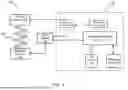
FIG. 1 illustrates a block diagram of an electronic vaporizer according to an embodiment;
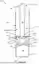
FIGS. 2A-D illustrate a sectional view of the electronic vaporizer according to various embodiments;
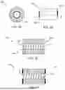
FIGS. 3A-D illustrate various views of a ceramic element with a filament inside the vaporization chamber; and
FIGS. 4A-D illustrate various plates of the ceramic element of the electronic vaporizer.
In the appended figures, similar components and/or features may have the same reference label. Further, various components of the same type may be distinguished by following the reference label by a second alphabetical label that distinguishes among the similar components. If only the first reference label is used in the specification, the description is applicable to any one of the similar components having the same first reference label irrespective of the second reference label.
DETAILED DESCRIPTION
The ensuing description provides preferred exemplary embodiment(s) only, and is not intended to limit the scope, applicability or configuration of the disclosure. Rather, the ensuing description of the preferred exemplary embodiment(s) will provide those skilled in the art with an enabling description for implementing a preferred exemplary embodiment. It is understood that various changes may be made in the function and arrangement of elements without departing from the spirit and scope as set forth in the appended claims.
Referring to FIG. 1, a block diagram of an electronic vaporizer 100 according to an embodiment is shown. The term “electronic vaporizer” used herein may be interchangeably used as vaporizing apparatus, vape pen, electronic cigarette, or vaporizer. The electronic vaporizer 100 includes a circuit card 102, a positive electrode 116, a negative electrode 118, a battery module 106, and a filament 120. The circuit card 102 includes a switch 104, a pressure sensor 108, a battery management system (BMS) 110, a state of charge (SoC) indicator 112, and a recharge input 114.
The electronic vaporizer 100 provides controlled vapor delivery rendered from a liquid. The electronic vaporizer 100 incorporates various components to ensure proper functionality and user safety in a small package. The following description provides an overview of electronic vaporizer 100 having multiple components performing interrelated functionalities.
The circuit card 102 controls and powers the functionality of the electronic vaporizer 100. The circuit card 102 is responsible for coordinating the operation of the different subsystems and managing the overall functionality of the electronic vaporizer 100. In some embodiments, the circuit card 102 includes a microcontroller or a similar processing unit that executes software instructions to control various aspects of the electronic vaporizer 100. In this embodiment, the BMS 110 includes a microcontroller for managing the battery module 106. The BMS 110 regulates charging and discharging of the battery module 106 to ensure safety and longevity. The BMS 110 controls other functions in the electronic vaporizer 100 in some embodiments.
The switch 104 is connected to the battery module 106. The switch 104 can be user-activated or can be activated using the pressure sensor 108 that allows the user to initiate vapor production. Activation of the switch 104 triggers the battery module 106 to activate the electronic vaporizer 100 by supplying current to the heat filament 120.
Power for the electronic vaporizer 100 is supplied by the battery module 106. The battery module 106 is a rechargeable energy storage component that provides the necessary electrical energy to power components of the electronic vaporizer 100. In one embodiment, the circuit card 102 includes the battery module 106. In an alternate embodiment, the battery module 106 is communicatively coupled to the circuit card 102. The BMS 110 is responsible for monitoring, conditioning, and controlling the battery module 106. The BMS 110 regulates the charging and discharging of the battery module 106 to increase its lifespan and performance. The BMS 110 also includes safety mechanisms to prevent overcharging, over-discharging, and short circuits, protecting both the battery module 106 and the user.
The SoC indicator 112 visually provides real-time information about the remaining battery capacity using LEDs or an electronic display. The SoC indicator 112 indicates the remaining charge in the battery module 106, allowing it to manage the usage accordingly. The SoC indicator 112 remains active when the switch 104 is active in one embodiment. In an alternate embodiment, SoC may remain activated for a predetermined period after the activation of the switch 104. The SoC indicator 112 reflects activation of the switch 104 to provide visual feedback that vapor is available for inhaling or will be available soon. The SoC indicator 112 increases intensity and/or change color of the LEDs or the electronic display when active, to indicate battery SoC and/or availability of vapor for inhalation. In one embodiment, the intensity of the SoC indicator 112 indicates the pressure sensed by the pressure sensor 108 and changes the current in the filament 120 to modulate the vapor production. The SoC indicator 112 may be part of a display having statuses such as usage, errors, low juice levels, and/or other statuses. In some embodiments, the SoC indicator 112 may be positioned at the end of the electronic vaporizer 100 away from the mouthpiece but can be anywhere visible to the user on the electronic vaporizer 100.
The recharge input 114 is a port or connector through which the battery module 106 can be recharged. The recharge input 114 allows the user to connect a suitable charging cable or adapter to replenish the battery's energy when it runs low. The recharge input 114 may be a USB-C port, a standard, or a proprietary port. In some embodiments, the recharge input 114 allows download of data to the electronic vaporizer 100 or upload of configuration/firmware to a data server. The SoC indicator 112 provides battery level feedback while being connected through the recharge input 114.
The pressure sensor 108 measures the pressure or suction exerted by the user during inhalation through the mouthpiece. Pressure levels vary with airflow and provide feedback to the circuit card 102, which can adjust the electronic vaporizer 100 output accordingly with variable power to the filament 120 in some embodiments. The pressure sensor 108 also acts upon the switch 104 to power the electronic vaporizer 100 to wake it from sleep mode while selectively enabling, disabling, and/or modulating power supplied from the battery module 106 to the filament 120.
The positive electrode 116 and the negative electrode 118 provide electrical current to the filament 120. In this embodiment, the filament 120 is wired or wirelessly coupled with the positive electrode 116 and the negative electrode 118 in various embodiments. The filament 120 is the heating element of the electronic vaporizer 100 and is designed to vaporize the e-liquid or the juice. The filament 120 can be made of nichrome, platinum, and/or stainless steel. In this embodiment, the filament 120 is deposited as a paste or liquid slurry including platinum and/or other metals or alloys on ceramic element. Heating the liquid or paste cures the filament 120 and bonds the filament 120 to a ceramic substrate. Current through the uncured filament can be used to generate the heat for curing, or an oven can be used to achieve the curing temperature. During normal operation, the circuit card 102 closes the circuit to the positive electrode 116 and/or the negative electrode 118, and electrical current passes through the filament 120, causing filament the 120 to heat up and vaporize the liquid. As a result, inhalable vapor is created.
With reference to FIGS. 2A-2D, various embodiments of a wireless atomizer or electronic vaporizer 100 are shown. Referring initially to the embodiment of FIG. 2A, a filament 120 is wound in a spiral and at least partially embedded in a ceramic element 206 in the shape of a cylinder of the electronic vaporizer 100-1. The filament is 80%, 75%, 70%, 65%, 60%, 55%, 50%, 45%, 40%, 35%, 30%, 25%, 20%, 15%, 10%, or 5% embedded in the ceramic element 206 after firing. The filament can be machine wound and automatically positioned within the ceramic element before firing while the ceramic is still viscous.
Referring next to FIG. 2B, a sectional view of an electronic vaporizer 100-2 according to an embodiment is shown. The electronic vaporizer 100-2 can be broken apart by unscrewing a threading 244 to separate the juice assembly from the battery assembly. There may be several juice assemblies used with the battery assembly that have different juice and capacities. A mouthpiece is also removable when adding more juice, for example.
The electronic vaporizer 100 includes a mouthpiece 200 that is removably attached to a tube 204 having a cavity 220. The mouthpiece 200 is a portion of the electronic vaporizer 100 that goes into the mouth of the user when vaping. The cavity 220 is generally cylindrical with different possible configurations to hold juice, but other embodiments may have a square, oval, or rectangular cavity in cross-section. A suction pipe 202 egresses vapor out of the mouthpiece 200 to the user of the electronic vaporizer 100. In different embodiments, the suction pipe 202 may egress vapor to the user from the sides or bottom of the electronic vaporizer 100. The battery module 106 is located at the opposite end from the mouthpiece 200 in this embodiment, but it may be configured differently in other embodiments.
The tube 204 is cylindrical in shape and closed at one end by the mouthpiece 200 after filling the cavity 220 with juice on one end. The mouthpiece 200 is removable to accommodate juice in case of refilling. In some embodiments, the tube 204 is transparent glass or plastic to allow visual feedback on the amount of juice available to make vapor. The juice passes through holes 208-1, 208-2 in the negative electrode 118 to a ceramic element 206. The ceramic element 206 is semi-permeable or porous to wick in the juice. The ceramic element 206 is a thin ceramic plate shaped as at least one of a disc, a square, a rectangle, or a disco-rectangle. The ceramic element 206 may be made of aluminum oxide or other ceramics. In one embodiment, the ceramic element 206 is wrapped in an aluminium sheet to provide support to and prevent breaking of the ceramic element 206. The ceramic element 206 is glued to the negative electrode 118 at the bottom of the tube 204, in this embodiment. However, the ceramic element 206 can be attached to the negative electrode 118 via other suitable methods.
There are multiple holes through the negative electrode 118 to supply the juice to the ceramic element 206. The holes 208-1, 208-2 are annularly arranged around the ceramic element 206. These holes can have different diameters and locations to expose porous the ceramic element 206 to the juice from the cavity 220. Cotton adjacent to the ceramic element 206 is optionally used to wick the juice from the cavity 220 more evenly across the surface of the ceramic element 206.
The ceramic element 206 is surrounded by an electrical conductor running from the negative terminal 232 of the battery module 106 to the negative electrode 118 coupled to the filament 120. The ceramic element 206 has a first surface fluidly coupled to the cavity 220 and a second surface parallel to the first surface. The second surface is adjacent to the vaporization chamber 210. The second surface includes the filament 120. In this embodiment, the first surface and the second surface are planar. A planar surface is flat two-dimensional with a specific length and width. In other embodiments, the first surface can be non-planar, but the second surface is planar. Ceramic element 206 includes a portal 242 in the center. Portal 242 extends from the second surface towards the first surface. In other embodiments, the portal 242 can be located on the periphery of the ceramic element 206. Portal 242 allows the vapor from the vaporization chamber 210 to pass across ceramic element 206 to enter a conduit 240.
The conduit 240 is a hollow air passage that runs from air intakes 224-1 and 224-2 to the suction pipe 202 to fluidly couple air intakes 224-1 and 224-2 to the user when sucking on mouthpiece 200 to ingest the vapor formed in the vaporization chamber 210. Although only two air intakes 224-1 and 224-2 are shown in the cross-section, other embodiments may have one, three, four, five, six, or more air intakes 224-1 and 224-2.
The second surface of ceramic element 206 at least partially exposes a first end and a second end of the filament 120. The negative electrode 118 is in compression contact with the first end of the filament 120 of the ceramic element 206 to make the electrical connection by providing a negative potential to the first end. The positive electrode 116 is in compression contact with the second end of the filament of the ceramic element 206 to make the electrical connection by providing a positive potential to the second end. When activated, the battery module 106 provides energy to the filament 120 to vaporize the liquid in the vaporization chamber 210. The second surface of the ceramic element 206 can be scratched or otherwise roughed up to facilitate electrical conductivity with compression contact. Some embodiments might include an electrically conductive paste, conductive washer, and/or silkscreened or viscously applied coating for the second surface of the ceramic element 206 to enhance electrical conductivity.
Additionally, a washer is used at the electrodes and the washer may have a cylindrical extension in the middle for insertion into the ceramic element 206 to enhance contact with filament 120. The washer may be made of silver, platinum, nichrome, gold, or other conductive material. The washer may have a rough surface to facilitate the conduction between electrodes and the filament 120. The washer could be as thin as foil or leaf (i.e., 1 micron) up to 1 mm thick or any thickness in range in various embodiments.
The washer may be deposited as a liquid, paste, or slurry at the same time as the filament 120. Firing would cure the filament 120 and washer at the same time into a contiguous electrical element. In another embodiment, a metal washer could have a cylindrical portion extending from the circular disc to provide more contact with the filament 120.
Negative pressure from suction at the mouthpiece 200 is sensed by the pressure sensor 108 on the circuit card 102. It closes the switch 104 to provide the battery module 106 power from a positive terminal 236 to the positive electrode 116 to heat the filament 120. Some embodiments can regulate the current to the filament 120 to more precisely heat the juice to a predetermined temperature for vapor production. Negative pressure at the suction pipe 202 causes an inflow of air at air intakes 224-1 and 224-2. The air enters the conduit 240 to carry the resulting vapor from the vaporization chamber 210 out to the mouthpiece 200 from where the user inhales the vapor. Other embodiments could forgo the pressure sensor 108 activation of the switch 104 with the user pressing a button to energize the filament 120 and make vapor.
Filament or liquid filament is deposited as a slurry, liquid, or paste on the second surface of the ceramic element 206. Heat or UV curing of the filament 120 after deposition hardens the filament 120 before use. In some embodiments, the second surface of the ceramic element 206 could be formed with a groove or is machined later to accept liquid filament 120. In one embodiment, the filament 120 is a platinum that when fired at 2000 degrees cures the filament 120. Liquid filament can be silkscreened or squeezed to fill the groove in the ceramic element 206 where the filament after firing is 80%, 75%, 70%, 65%, 60%, 55%, 50%, 45%, 40%, 35%, 30%, 25%, 20%, 15%, 10%, or 5% embedded. Some embodiments do not embed the filament 120 at all into the ceramic element 206 by depositing or printing the liquid filament on the second surface using photolithography. The filament 120 is exposed from the second surface of the ceramic element 206. For example, the height of filament 120 could exceed the thickness of the ceramic element 206 by 80%, 75%, 70%, 65%, 60%, 55%, 50%, 45%, 40%, 35%, 30%, 25%, 20%, 15%, 10%, 5%, or 0% to allow electrodes to make friction contact with the filament 120 to allow electrical conduction during normal operation.
The filament 120 heats the ceramic element 206 to vaporize the juice absorbed by the ceramic element 206 during normal operation. The filament 120 is configured to heat the liquid to change its state to the inhalable vapor inside the vaporization chamber 210 using the suction from the user to evacuate the inhalable vapor towards the mouthpiece 200 during normal operation.
In another embodiment, the electronic vaporizer 100-2 may be rectangular in shape and has a basic operation similar to the electronic vaporizer 100. The heating of the liquid from the ceramic element 206 changes state with heat inside the vaporization chamber 210. Different shapes and arrangements of the various components of the electronic vaporizer 100-2 are possible in other embodiments. The liquid filament can be applied in the same way for curing prior to use.
Referring next to FIG. 2C, another embodiment of the electronic vaporizer 100-3 is shown. The electronic vaporizer 100-3 is generally rectangular with similar basic operation to the embodiment of FIG. 2B. The heating of the liquid from the ceramic element 206 changes state with heat inside the vaporization chamber 210. Different shapes and arrangement of the various components of the electronic vaporizer are possible in other embodiments. The liquid filament can be applied in the same way for curing prior to use.
The battery module 106 in the electronic vaporizer 100-3 is electrically coupled with the positive electrode 116 and the negative electrode 118 with the switch 104 to selectively activate the filament 120. In some embodiments, the tube 204 is held in compression contact with the negative electrode 118 near the center of the electronic vaporizer 100. To connect the tube 204 to the other electronic vaporizer components, glue, a press fit, or a plastic weld may be utilized annularly around it. Although the electronic vaporizer 100 is cylindrically shaped in cross-section in this embodiment, other embodiments may be square, oval, or rectangular.
To reduce the frequency of charging the battery module 106, the electronic vaporizer 100 incorporates power management techniques and innovative battery technologies. For example, current and/or voltage to the filament 120 can be regulated according to a temperature in a vaporization chamber 210, a velocity of the airflow, and/or an ambient air temperature. This results in extended usage time between charges, allowing users to enjoy their vaping experience for longer durations.
With reference to FIG. 2D, another embodiment of the electronic vaporizer 100-4 is shown in a side sectional view. This embodiment of the electronic vaporizer 100-4 uses a ceramic element 206 that is planar with the filament facing the conduit 240 to form the vaporization chamber 210. The juice from the cavity 220 passes through the holes 208 to wet and infuse the ceramic element 206. Air intakes 224 are distributed around the periphery of the electronic vaporizer 100 with two shown in cross-section, but there could be three, four, five, six, eight, or ten in various embodiments. Airflow goes downstream from the intakes 224 through conduit 240 to the vaporization chamber 210. After the airflow is infused with vapor, the airflow passes through a portal 242 in the ceramic element 206 to the mouthpiece 200 for ingest. The portal 242 could be circular, square, rectangular, or oval in various embodiments.
Referring next to FIGS. 3A-3D, various views of a ceramic element 206 with a filament 120 inside the vaporization chamber 210 are shown. In FIG. 3A, a top view of the ceramic element 206 shows the filament 120 in the center. The filament 120 has a washer 304 around the ceramic element 206. The filament 120 could run contiguously to the top and bottom surfaces in other embodiments. In one embodiment, the ceramic element 206 is 0.221 inches tall from top to bottom, 0.179 inches in outer diameter, and the inside of the cylinder being 0.075 inches in diameter.
Referring next to FIG. 3B, side view of the ceramic element 206 is shown. In this embodiment, the filament 120 is printed on the inside of the ceramic element 206-1 and extends past the top end 300-1 and bottom end 300-2 to provide better contact with the positive electrode 116 and the negative electrode 118 respectively. To apply the liquid electrode, an injection needle with a horizontal port is placed at the center surface of the ceramic element 206 starting at the top or bottom. The ceramic element 206 is rotated while the injection needle is moved along its axis toward the other end to print the liquid electrode.
Referring next to FIG. 3C, a cross-section (along the A-A cross section) schematic view of the filament 120 at least partially inside the vaporization chamber 210 according to an embodiment is shown. The filament 120 has the top end 300-1 and the bottom end 300-2. The top end 300-1 meets the top of the ceramic element 206 to allow electrical contact. The top end 300-1 is exposed on the top of the ceramic element 206 and the bottom end 300-2 is exposed at the bottom. The top end 300-1 of the filament 120 conducts current along the helical winding to the bottom end 300-2. The positive electrode 116 has compression contact with the top end 300-1 to allow a current to flow during normal operation. The negative electrode 118 has compression contact with the bottom end 300-2 to allow the current flow during normal operation. In some embodiments, the filament 120 is formed in the shape of a spring that is made of nichrome wire.
The top end 300-1 of the filament 120 is in compression contact with the positive electrode 116, while the bottom end 300-2 is in compression contact with the negative electrode 118. With such an arrangement wires are not needed using friction compression between the filament 120 and the positive electrode 116 and the negative electrode 118. In this embodiment, electrical connection is established without physical wires or soldering needed. This wireless connectivity is without the need for physical wiring. For example, the top end 300-1 may be formed as a first coil and is provided with the battery module 106, where a current is induced into the top end 300-1 via the positive electrode 116 to energize the filament 120 to heat the juice.
In some embodiments, to ensure optimal conductivity, the top end 300-1 of the filament 120 is electrically connected to the positive electrode 116, while the bottom end 300-2 is electrically connected to the negative electrode 118. At least one of these electrical connections is achieved through the implementation of a washer, made of silver, nichrome, gold, or other conductive material.
Referring next to FIG. 3D, washers 304 on the top end 300-1 and the bottom end 300-2 of a ceramic element 206-2 are shown. The washers 304 are electrically conductive to bridge the filament 120 electrically with the positive electrode 116 and the negative electrode 118. The washers 304 could be made of silver, platinum, nichrome, gold, or other conductive material. The washer 304 serves to improve the conductivity between the filament 120 and the respective electrodes. The washer 304 could have a rough surface to facilitate the conduction between the electrodes and the filament 120. The washer 304 could be as thin as foil or leaf (i.e., 1 micron) up to 1 mm thick or any thickness in that range in various embodiments.
The washers 304 could be deposited as a liquid, paste or slurry at the same time as the filament 120 in some embodiments. Firing would cure the filament and washers at the same time into a contiguous electrical element. In another embodiment, a metal washer could have a cylindrical portion extending from the circular disk into the vaporization chamber 210 to provide more contact with the filament 120.
In other embodiments, the filament 120 may be formed in a square or rectangular winding for embodiments of the vaporization chamber 210 that have a similar shape. The filament 120 provides a heating element that extends from the first end to the second end. Resistance in the filament 120 produces heat as a function of the voltage across or current through the filament 120.
Electrical conduction between the ends and the electrodes completes the circuit to provide power from the battery module 106 to the filament 120. In another embodiment, the top end 300-1 and or the bottom end 300-2 of the filament 120 is modified to incorporate additional electrical contact on the top of the ceramic element 206-2, which radiate outwards from the vaporization chamber 210. Additional filament wire could spiral out along the top of the ceramic element 206-2 to provide 2, 3, 4, or 5 concentric loops (circular, square, or rectangular) to provide additional exposure of the ends of the filament 120 for better electrical conduction when in compression contact with the electrodes.
Referring next to FIG. 4A, a disc-shaped plate or a disc plate 402-1 of the ceramic element 206 is shown. The disc plate 402-1 has a first surface fluidly coupled to the juice and a second surface adjacent to vaporization chamber 210. The disc plate 402-1 includes a circular spiral heating element or filament 120-1 printed on the second surface that vaporizes the juice. In an alternate embodiment, filament 120-1 may have various shapes, such as a rectangular spiral, an oval spiral, or a square spiral. The top end 300-1 and the bottom end 300-2 of filament 120-1 are at least partially exposed from the second surface. The center of disc plate 402-1 includes a circular portal 242-1. In an alternate embodiment, the circular portal 242-1 could be oval, square, or rectangular. The circular portal 242-1 allows the vapor from vaporization chamber 210 to pass across the disc plate 402-1 toward the mouthpiece 200 of the electronic vaporizer 100. In this embodiment of disc plate 402-1, the edges 122-1 of disc plate 402-1 are chamfered to allow simplified assembly of disc plate 402-1. The chamfered edges further eliminate the shape edges from disc plate 402-1, thus reducing the risk of injury during the assembly.
In one embodiment the thickness of disc plate 402-1 is less than 1 millimeter. In other embodiments, the thickness of disc plate 402-1 is between 1 to 4 millimeters. In yet another embodiment, the thickness of disc plate 402-1 is between 2 to 4 millimeters.
Referring next to FIG. 4B, the ceramic element 206 as a square plate 402-2 is shown. The square plate 402-2 has a first surface fluidly coupled to the juice and a second surface adjacent to vaporization chamber 210. The second surface includes a square spiral heating element or filament 120-2 printed on the second surface that vaporizes the juice, in one embodiment. In other embodiments, filament 120-2 could be a rectangular spiral, an oval spiral, or a circular spiral. The top end 300-1 and the bottom end 300-2 of the filament 120-2 are at least partially exposed from the second surface. In one embodiment, the center of the square plate 402-2 includes a square-shaped portal 242-2. In other embodiments, the square-shaped portal 242-2 could be oval, circular, or rectangular. The square-shaped portal 242-2 allows the vapor from vaporization chamber 210 to pass across the square plate 402-2 toward the mouthpiece 200 of the electronic vaporizer 100.
In one embodiment, the thickness of the square plate 402-2 is less than 1 millimeter. In other embodiments, the thickness of the square plate 402-2 is between 1-3 millimeters. In yet other embodiments, the thickness of the square plate 402-2 is between 2 to 3 millimeters.
Referring next to FIG. 4C, the ceramic element 206 as a disco-rectangular plate 402-3 is shown. The disco-rectangular plate 402-3 has a first surface fluidly coupled to the juice and a second surface adjacent to the vaporization chamber 210. The second surface includes a square spiral heating element or the filament 120-3 printed on the second surface that vaporizes the juice. In other embodiments, the filament 120-3 could be a rectangular spiral, an oval spiral, or a circular spiral. The top end 300-1 and the bottom end 300-2 of the filament 120-3 are at least partially exposed from the second surface. The center of disco-rectangular plate 402-3 includes a rectangular portal 242-3. In other embodiments, the rectangular portal 242-3 could be oval, circular, or rectangular. The rectangular portal 242-3 allows the vapor from vaporization chamber 210 to pass across the disco-rectangular plate 402-3 towards mouthpiece 200 of electronic vaporizer 100.
In one embodiment, the thickness of the disco-rectangular plate 402-3 is less than 1 millimeter. In another embodiment the thickness of the disco-rectangular plate 402-3 is between 1-3 millimeters. In yet another embodiment, the thickness of the disco-rectangular plate 402-3 is between 2 to 3 millimeters.
Referring next to FIG. 4D, the ceramic element 206 as another disco-rectangular plate 402-4 having a first surface and a second surface is shown. The second surface is adjacent to the vaporization chamber 210. A zig-zag shaped heating element or a filament 120-4 is printed on the second surface. In other embodiments, the filament 120-4 could be shaped as a rectangular spiral, a circular spiral, or a square spiral. The filament 120-4 has the top end 300-1 and the bottom end 300-2 at least partially exposed from the second surface. In this embodiment, the vapor from the vaporization chamber 210 passes across the disco-rectangular plate through portal 242 which is located on the periphery of disco-rectangular plate.
Specific details are given in the above description to provide a thorough understanding of the embodiments. However, it is understood that the embodiments may be practiced without these specific details. For example, circuits may be shown in block diagrams in order not to obscure the embodiments in unnecessary detail. In other instances, well-known circuits, processes, algorithms, structures, and techniques may be shown without unnecessary detail in order to avoid obscuring the embodiments.
Implementation of the techniques, blocks, steps and means described above may be done in various ways. For example, these techniques, blocks, steps and means may be implemented in hardware, software, or a combination thereof. For a hardware implementation, the processing units may be implemented within one or more application specific integrated circuits (ASICs), digital signal processors (DSPs), digital signal processing devices (DSPDs), programmable logic devices (PLDs), field programmable gate arrays (FPGAs), processors, controllers, micro-controllers, microprocessors, other electronic units designed to perform the functions described above, and/or a combination thereof.
Also, it is noted that the embodiments may be described as a process which is depicted as a flowchart, a flow diagram, a swim diagram, a data flow diagram, a structure diagram, or a block diagram. Although a depiction may describe the operations as a sequential process, many of the operations can be performed in parallel or concurrently. In addition, the order of the operations may be re-arranged. A process is terminated when its operations are completed but could have additional steps not included in the figure. A process may correspond to a method, a function, a procedure, a subroutine, a subprogram, etc. When a process corresponds to a function, its termination corresponds to a return of the function to the calling function or the main function.
Furthermore, embodiments may be implemented by hardware, software, scripting languages, firmware, middleware, microcode, hardware description languages, and/or any combination thereof. When implemented in software, firmware, middleware, scripting language, and/or microcode, the program code or code segments to perform the necessary tasks may be stored in a machine-readable medium such as a storage medium. A code segment or machine-executable instruction may represent a procedure, a function, a subprogram, a program, a routine, a subroutine, a module, a software package, a script, a class, or any combination of instructions, data structures, and/or program statements. A code segment may be coupled to another code segment or a hardware circuit by passing and/or receiving information, data, arguments, parameters, and/or memory contents. Information, arguments, parameters, data, etc. may be passed, forwarded, or transmitted via any suitable means including memory sharing, message passing, token passing, network transmission, etc.
For a firmware and/or software implementation, the methodologies may be implemented with modules (e.g., procedures, functions, and so on) that perform the functions described herein. Any machine-readable medium tangibly embodying instructions may be used in implementing the methodologies described herein. For example, software codes may be stored in a memory. Memory may be implemented within the processor or external to the processor. As used herein the term “memory” refers to any type of long term, short term, volatile, nonvolatile, or other storage medium and is not to be limited to any particular type of memory or number of memories, or type of media upon which memory is stored.
Moreover, as disclosed herein, the term “storage medium” may represent one or more memories for storing data, including read only memory (ROM), random access memory (RAM), magnetic RAM, core memory, magnetic disk storage mediums, optical storage mediums, flash memory devices and/or other machine-readable mediums for storing information. The term “machine-readable medium” includes but is not limited to portable or fixed storage devices, optical storage devices, and/or various other storage mediums capable of storing that contain or carry instruction(s) and/or data.
While the principles of the disclosure have been described above in connection with specific apparatuses and methods, it is to be clearly understood that this description is made only by way of example and not as limitation on the scope of the disclosure.
Claims
1. A vaporizing apparatus for converting a liquid into an inhalable vapor, the vaporizing apparatus comprising:
a mouthpiece of the vaporizing apparatus, wherein the mouthpiece is coupled to a conduit;
a battery module away from the mouthpiece of the vaporizing apparatus;
a tank having a cavity, wherein the conduit is located between the mouthpiece and the battery module of the vaporizing apparatus;
a ceramic element fluidly coupled with the cavity, the ceramic element comprising a top, a bottom and a vaporization chamber, wherein:
the vaporization chamber is fluidly coupled with the conduit,
the vaporization chamber extends from the top to the bottom,
the vaporization chamber has a length, and
the vaporization chamber has an inner diameter;
a filament, wherein the filament is formed in a helical winding having an outer diameter and a height, wherein:
the outer diameter is equal to or greater than the inner diameter,
the height of the filament is greater than or equal to the length of the vaporization chamber,
the filament has a first end and a second end,
the first end is exposed on the top, and
the second end is exposed on the bottom;
a first electrode, wherein the first electrode has compression contact with the first end to allow a current to flow during normal operation; and
a second electrode, wherein the second electrode has compression contact with the second end to allow the current to flow during normal operation, whereby the filament heats the liquid to change its state to the inhalable vapor using the current, and suction at the mouthpiece evacuates the inhalable vapor toward the mouthpiece.
2. The vaporizing apparatus for converting the liquid into the inhalable vapor of claim 1, wherein the filament is wirelessly coupled with the first electrode and the second electrode.
3. The vaporizing apparatus for converting the liquid into the inhalable vapor of claim 1, the vaporizing apparatus comprising a tube electrically coupled with the first electrode or the second electrode.
4. The vaporizing apparatus for converting the liquid into the inhalable vapor of claim 1, wherein the first end of the filament conducts the current along the helical winding to the second end.
5. The vaporizing apparatus for converting the liquid into the inhalable vapor of claim 1, wherein:
the conduit has an opening at the top or at the bottom, and
the conduit is fluidly coupled with a suction pipe.
6. The vaporizing apparatus for converting the liquid into the inhalable vapor of claim 1, further comprising an air pipe, wherein the air pipe has compression contact with the filament.
7. An electronic vaporizer for converting a liquid into an inhalable vapor, the electronic vaporizer comprising:
a battery module away from a mouthpiece of the electronic vaporizer;
a tube having a cavity, wherein the tube is located between the mouthpiece and the battery module of the electronic vaporizer;
a ceramic element inside the cavity, the ceramic element comprising a top, a bottom, and a conduit, wherein:
the conduit extends from the top to the bottom,
the conduit has a length, and
the conduit has an inner diameter;
a filament, wherein the filament is formed in a helical winding having an outer diameter and a height, wherein:
the outer diameter is greater than the inner diameter,
the height of the filament is equal to the length of the conduit,
the filament has a first end and a second end,
the first end is exposed on the top, and
the second end is exposed on the bottom;
a first electrode, wherein the first electrode is wirelessly coupled with the first end to allow a current to flow during normal operation; and
a second electrode, wherein the second electrode is wirelessly coupled with the second end to allow the current to flow during normal operation, whereby the filament heats the liquid to change its state to the inhalable vapor using the current to evacuate the inhalable vapor toward the mouthpiece during normal operation.
8. The electronic vaporizer for converting the liquid into the inhalable vapor of claim 7, wherein the filament is partially embedded in the ceramic element.
9. The electronic vaporizer for converting the liquid into the inhalable vapor of claim 7, wherein the filament is a piece of metal.
10. The electronic vaporizer for converting the liquid into the inhalable vapor of claim 7, wherein the tube has compression contact with the first or the second electrode to pass current to the filament.
11. The electronic vaporizer for converting the liquid into the inhalable vapor of claim 7, wherein the first end of the filament conducts current along the helical winding to the second end.
12. The electronic vaporizer for converting the liquid into the inhalable vapor of claim 7, wherein the ceramic element is a porous ceramic.
13. The electronic vaporizer for converting the liquid into the inhalable vapor of claim 7, wherein the cavity further comprises a plurality of openings in the tube allowing fluid communication between the ceramic element and the liquid outside the tube.
14. A vaporizer for converting a liquid into an inhalable vapor, the vaporizer comprising:
a battery module away from a mouthpiece of the vaporizer;
a housing having a cavity, wherein the housing is located between the mouthpiece and the battery module;
a ceramic element inside the cavity, the ceramic element comprising a top, a bottom and a conduit, wherein:
the conduit extends from the top to the bottom, and
the conduit has a length;
a filament, wherein the filament is embedded in the ceramic element having a height, wherein:
the filament is a piece of metal,
the height of the filament is greater than the length of the conduit, and
the filament has a first end and a second end;
a first electrode, wherein the first electrode has compression contact with the first end to allow a current to flow during normal operation; and
a second electrode, wherein the second electrode has compression contact with the second end to allow the current to flow during normal operation, wherein the filament is configured to heat the liquid to change its state to the inhalable vapor using the current to evacuate the inhalable vapor towards the mouthpiece during a normal operation.
15. The vaporizer for converting the liquid into the inhalable vapor of claim 14, wherein the filament is molded within the ceramic element.
16. The vaporizer for converting the liquid into the inhalable vapor of claim 14, wherein the housing has a square shape.
17. The vaporizer for converting the liquid into the inhalable vapor of claim 14, wherein the filament is shaped as a square winding.
18. The vaporizer for converting the liquid into the inhalable vapor of claim 14, wherein:
the filament heats up the ceramic element, and
the ceramic element when hot, heats liquid absorbed by the ceramic element during normal operation.
19. The vaporizer for converting the liquid into the inhalable vapor of claim 14, wherein the housing has compression contact with the first or the second electrode.
20. The vaporizer for converting the liquid into the inhalable vapor of claim 14, wherein the height of the filament is equal to the length of the conduit.
21-60. (canceled)
Images & Drawings included:


Sources:
- United States Patent and Trademark Office - verify current appl. status at the USPTO↗
Similar patent applications:
- » 20210288688
Systems and methods for wireless atomic clock synchronization using ultra wideband (UWB) pulse trains - » 20220116071
Systems and methods for wireless atomic clock synchronization using ultra wideband (UWB) pulse trains - » 20210045455
Aerosol delivery device including a wirelessly-heated atomizer and related method - » 20170127722
Aerosol delivery device including a wirelessly-heated atomizer and related method - » 20250160415
AEROSOL DELIVERY DEVICE INCLUDING A WIRELESSLY-HEATED ATOMIZER AND RELATED METHOD - » 20240298707
AEROSOL DELIVERY DEVICE INCLUDING A WIRELESSLY-HEATED ATOMIZER AND RELATED METHOD - » 20200114037
Liquid atomizing system and device electrically charged in wireless manner
Recent applications in this class:
- » 20250169539 2025-05-29
AEROSOL-GENERATING APPARATUS - » 20250169538 2025-05-29
ATOMIZING ASSEMBLY AND ELECTRONIC ATOMIZING DEVICE - » 20250169537 2025-05-29
AEROSOL PROVISION DEVICE COMPRISING A HEAT CONDUCTING LINING - » 20250160413 2025-05-22
HEATING ELEMENT FOR ELECTRONIC VAPORIZATION DEVICES - » 20250160412 2025-05-22
ATOMIZATION CORE AND ELECTRONIC ATOMIZATION DEVICE - » 20250160411 2025-05-22
Heating Apparatus for an Aerosol Generating Device - » 20250151795 2025-05-15
ELECTRONIC SMOKING ARTICLE INCLUDING A HEATING APPARATUS IMPLEMENTING A SOLID AEROSOL GENERATING SOURCE - » 20250151794 2025-05-15
SMOKING ARTICLE INCORPORATING A CONDUCTIVE SUBSTRATE - » 20250151793 2025-05-15
ANTI-DRY HEATING METHOD, ATOMIZATION DRIVING CIRCUIT, ELECTRONIC ATOMIZATION APPARATUS, AND RELATED APPARATUS - » 20250151792 2025-05-15
AEROSOL DELIVERY SYSTEM