ELASTIC MODULE AND ELASTIC CUSHION
US20250331653A1
2025-10-30
19/189,338
2025-04-25
Smart Summary: An elastic module is made up of several spring units that can be connected together. Each spring unit has two springs: a first spring and a second spring. The first spring can be compressed to lock it in place, and it has an end cover at the top. The second spring attaches to this end cover, completing the spring unit. This design allows for flexibility and easy assembly of the elastic module. 🚀 TL;DR
Abstract:
An elastic module includes a plurality of spring units. The plurality of spring units are configured to be spliced together to form the elastic module, and each of the plurality of spring units includes a first spring and a second spring. The first spring is configured to be axially compressed to a locking position, and an upper end of the first spring is disposed with an end cover. The second spring is detachably connected to the end cover to form a corresponding one of the plurality of spring units.
Applicant:
Interested in similar patents?
Get notified when new applications in this technology area are published.
Classification:
A47C27/062 » CPC further
Spring, stuffed or fluid mattresses or cushions specially adapted for chairs, beds or sofas with spring inlays; Spring inlays of different resiliencies
A47C27/07 » CPC main
Spring, stuffed or fluid mattresses or cushions specially adapted for chairs, beds or sofas with spring inlays; Spring inlays Attaching, or interconnecting of, springs in spring inlays
A47C27/06 IPC
Spring, stuffed or fluid mattresses or cushions specially adapted for chairs, beds or sofas with spring inlays Spring inlays
Description
RELATED APPLICATIONS
This application claims priority to Chinese patent application number 202410501946.X, filed on Apr. 25, 2024. Chinese patent application number 202410501946.X is incorporated herein by reference.
FIELD OF THE DISCLOSURE
The present disclosure relates to the field of furniture, particularly to an elastic module and an elastic cushion.
BACKGROUND OF THE DISCLOSURE
Furniture, such as mattresses, are characterized by large volume and difficulty in transportation. Most existing mattresses lack disassembly functionality or cannot be easily restored after disassembly. However, with the evolution of modern lifestyles, furniture, like mattresses, increasingly requires frequent assembly and disassembly to accommodate population migration and outdoor leisure needs.
Currently, some detachable mattresses have been developed, where each spring unit is independent and interconnectable. However, a mattress typically employs a large number of independent spring units. Even when disassembled, these units occupy significant space during transportation and are challenging to manually transport quickly.
Therefore, there is a need to redesign spring units to reduce their spatial footprint during transportation and facilitate manual handling.
Additionally, users have varying preferences for mattress firmness—some prefer soft mattresses, while others favor firm ones. To replace springs with different firmness levels, users must disassemble and reinstall all components of the independent spring units, which is highly inconvenient and prone to damage.
BRIEF SUMMARY OF THE DISCLOSURE
The present invention provides an elastic module and an elastic cushion that reduce an occupied space during disassembled transportation, facilitate manual handling, and allow users to replace springs with varying firmness levels according to their needs without disassembling the spring units.
In order to solve the above technical problems, the present disclosure provides an elastic module, and the elastic module comprises a plurality of spring units. The plurality of spring units are configured to be spliced together to form the elastic module, and each of the plurality of spring units comprises a first spring and a second spring. The first spring is configured to be axially compressed to a locking position, and an upper end of the first spring is disposed with an end cover. The second spring is detachably connected to the end cover to form a corresponding one of the plurality of spring units.
In a preferred embodiment, a bottom of the second spring is disposed with a bottom cover, and the bottom cover of the second spring is connected to the end cover by rotation, insertion, or threads.
In a preferred embodiment, the bottom cover of the second spring is symmetrically provided with two rotation-connecting members, and each of the two rotation-connecting members comprises a first part and a second part. The first part extends axially from a bottom of a base, and the second part is located at an end of the first part and extends radially outward from a center of the first part.
In a preferred embodiment, a top of the end cover comprises two sliding rails corresponding to the two rotation-connecting members in a one-to-one correspondence as a mounting structure, and each of the two sliding rails is a strip-shaped recessed hole. A width of the strip-shaped recessed hole gradually narrows along a rotation direction of the two rotation-connecting members, and a width of a narrowest part of the strip-shaped recessed hole is smaller than a width of the second part.
In a preferred embodiment, a bottom of the bottom cover of the second spring is disposed with an insertion member.
In a preferred embodiment, a top of the end cover of the first spring comprises an insertion groove configured to correspond to the insertion member.
In a preferred embodiment, the bottom of the bottom cover of the second spring is disposed with a conical insertion member with a gradually decreasing radius along an insertion direction of the conical insertion member. The conical insertion member is configured to be inserted into the insertion groove to enable the conical insertion member to be self-locked along a vertical direction.
In a preferred embodiment, the bottom of the bottom cover is symmetrically provided with two tapered insertion members with a gradually decreasing width along an insertion direction of the two tapered insertion members, and a tapered groove is formed between the two tapered insertion members. Two sides of the top of the end cover comprise two tapered insertion grooves configured to cooperate with the two tapered insertion members, and a tapered protrusion is formed between the two tapered insertion grooves. The two tapered insertion members are configured to be inserted into the two tapered insertion grooves, and a double-conical surface structure formed by the two tapered insertion members and the tapered protrusion is self-locked along a vertical direction.
In a preferred embodiment, an inside the end cover comprises a threaded connecting member, and outer threads are provided on an outer wall of the threaded connecting member. The bottom cover is a circular ring, and an inner wall of the circular ring is provided with inner threads. The bottom cover of the second spring is threadedly connected to the threaded connecting member.
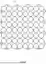
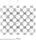
In a preferred embodiment, the plurality of spring units are arranged in a staggered arrangement to form a hexagonal distribution.
The present disclosure provides an elastic module, and the elastic module comprises a plurality of spring units and a connecting plate. The plurality of spring units are configured to be spliced together to form the elastic module, and each of the plurality of spring units comprises a first spring and a second spring. The first spring is configured to be axially compressed to a locking position, and an upper end of the first spring is disposed with an end cover. A bottom of the second spring is disposed with a bottom cover, and the end covers of the first springs of the plurality of spring units and the bottom covers of the second springs of the plurality of spring units are respectively connected to two sides of the connecting plate to form the elastic module.
In a preferred embodiment, a lower side of the connecting plate comprises a first insertion structure into which the end cover of the first spring is inserted, and an upper side of the connecting plate comprises a second insertion structure into which the bottom cover of the second spring is inserted.
In a preferred embodiment, the first springs of the plurality of spring units are arranged in a transverse direction and a longitudinal direction to be in a matrix arrangement, or the first springs of the plurality of spring units are arranged in a staggered arrangement to form a hexagonal distribution.
In a preferred embodiment, the second springs of the plurality of spring units are arranged in a transverse direction and a longitudinal direction to be in a matrix arrangement, or the second springs of the plurality of spring units are arranged in a staggered arrangement to form a hexagonal distribution.
In a preferred embodiment, the upper side and the lower side of the connecting plate each comprises a plurality of circular protruding rings extending along a vertical direction, and the end cover and the bottom cover each comprises a recessed hole that is interference-fitted with a corresponding one of the plurality of circular protruding rings.
In a preferred embodiment, the upper side and the lower side of the connecting plate are each formed with a plurality of annular insertion grooves, and an inside of each of the plurality of annular insertion grooves comprises a tapered insertion member configured to be connected to the bottom cover or the end cover to be self-locked along an axial direction of the first spring.
The present disclosure provides an elastic module, and the elastic module comprises a plurality of spring units. Each of the plurality of spring units comprises a first spring and a second spring, and the first spring is configured to be axially compressed to a locking position. An upper end of the first spring is disposed with an end cover, and the second spring is detachably connected to the end cover. The plurality of spring units are arranged in a transverse direction and a longitudinal direction to be in a matrix arrangement to enable adjacent rows or columns of the plurality of spring units to be formed with gaps, and one or more third springs are inserted into one or more of the gaps to form the elastic module.
In a preferred embodiment, the second spring is in an inverted conical shape, and the one or more third springs are in a positive conical shape.
In a preferred embodiment, the second spring and the one or more third springs are cylindrical in a same size.
The present disclosure provides an elastic module, and the elastic module comprises a plurality of spring units. The plurality of spring units are configured to be spliced together to form the elastic module, and each of the plurality of spring units comprises a first spring and at least two second springs. The first spring is configured to be axially compressed to a locking position, and an upper end of the first spring is disposed with an end cover. The at least two second springs are detachably connected to the end cover to form a corresponding one of the plurality of spring units.
In a preferred embodiment, the end cover comprises at least two mounting structures, and the at least two second springs are connected to the end cover through the at least two mounting structures by insertion or rotation.
In a preferred embodiment, the second spring is configured to be axially compressed to a locking position.
In a preferred embodiment, the second spring is a hollow structure, and the second springs of the plurality of spring units are configured to be stacked to each other along an axial direction of the second springs.
In a preferred embodiment, a flexible spring top cover is provided on an upper side of the second spring, and the flexible spring top cover is inserted into the hollow structure.
In a preferred embodiment, an end of the first spring facing the end cover is disposed with a base, and a lower end of the end cover is disposed with a first buckling structure extending along a spring compression direction. An upper end of the base is disposed with a second buckling structure extending along the spring compression direction. When the first spring is in the locking position, the first buckling structure and the second buckling structure are buckled to each other.
In a preferred embodiment, two hooks are symmetrically provided on a lower end surface of the end cover in the spring compression direction as the first buckling structure. Each of the two hooks comprises a connecting portion and a hook portion, and the hook portion is disposed on an outer side of the connecting portion.
In a preferred embodiment, two sides of the base extend toward a center of the base to form two buckling members as the second buckling structure, and each of the two buckling members comprises a connecting arm and a buckling portion. The buckling portion is located at a distal end of the connecting arm, and the buckling portion is suspended so that the two buckling members have elasticity to be pushed up by the two hooks. When the first spring is in the locking position, the hook portion and the buckling portion are axially interlocked with each other to achieve a buckling connection.
In a preferred embodiment, a distance between the buckling portion and a central axis of the first spring gradually decreases along the spring compression direction of the first spring, so that the buckling portion forms an inclined surface. Due to an external force, the hook portion slides down along the inclined surface to be buckled to a bottom end of the buckling portion, so that the two hooks and the two buckling members are axially interlocked with each other.
In a preferred embodiment, due to the external force, the hook portion pushes the buckling portion until the hook portion is separated from the buckling portion to release the buckling connection.
In a preferred embodiment, a lower end surface of the end cover is disposed with a pushing member extending along the spring compression direction of the first spring, and two sides of the pushing member are respectively disposed with one or more elastic position-limiting members as the first buckling structure.
In a preferred embodiment, an upper end surface of the base is disposed with a position-limiting groove configured to cooperate with the one or more elastic position-limiting members as the second buckling structure, and a side wall of the position-limiting groove is formed with a position-limiting wall. Due to an external force, the pushing member drives the one or more elastic position-limiting members to slide into the position-limiting groove, so that the one or more elastic position-limiting members are stuck by the position-limiting wall to achieve a buckling connection.
In a preferred embodiment, the first spring comprises a spring and a cloth cover, and the cloth cover is wrapped on an outside of the spring. An outside of the cloth cover at a top of the spring is disposed with a ring, and a lower surface of the ring is recessed inward along a vertical direction to form an annular groove. A bottom surface of the end cover is disposed with a positioning structure, and the positioning structure is buckled to the annular groove to be interlocked with the ring.
In a preferred embodiment, the ring comprises a first portion and a second portion, and the second portion is disposed on an inside of the cloth cover. The first portion is disposed on the outside of the cloth cover, and the first portion and the second portion are buckled and fixed to the spring.
In a preferred embodiment, the first spring comprises a spring and a cloth cover, and the cloth cover is wrapped on an outside of the spring. An outside of the cloth cover at a bottom of the spring is disposed with a ring, and an outside of the ring comprises a protrusion. A radial outside of the base forms a U-shaped groove, and a top of an outer wall of the U-shaped groove forms a positioning structure. The ring is buckled to the U-shaped groove, and the U-shaped groove and the ring are axially interlocked with each other.
In a preferred embodiment, a spring in the second spring is detachable.
In a preferred embodiment, an elastic cushion comprises the elastic module.
Compared with the existing techniques, the technical solution has the following advantages.
Compared with the existing techniques, the beneficial effects of the present disclosure are as follows. The elastic module of the present disclosure allows each of the plurality of spring units to be disassembled into the first spring and the second spring, which are detachably installed. The first spring can be compressed axially to a locking position, thereby reducing the occupied space during disassembled transportation and facilitating manual handling. Additionally, the second spring, designed for direct contact with a human body, can be replaced without disassembling the entire spring unit, enabling users to customize firmness levels by the second springs of varying stiffness, thus meeting diverse user demands.
BRIEF DESCRIPTION OF THE DRAWINGS
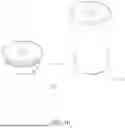
FIG. 1 is a schematic view of a spring unit in Embodiment 1.
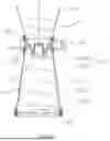
FIG. 2 is a schematic view of a first spring in Embodiment 1.
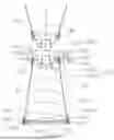
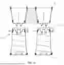
FIG. 3 is a schematic view of the first spring in a compressed state in Embodiment 1.
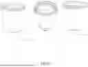
FIG. 4 is a schematic view of a second spring with a conical insertion member in Embodiment 1.
FIG. 5 is a schematic view of the second spring with two rotation-connecting members in Embodiment 1.
FIG. 6 is a schematic view of a stacked state of the second springs in FIG. 4.
FIG. 7 is a schematic view of a stacked state of the second springs in FIG. 5.
FIG. 8 is a schematic view of the second springs with various nestable shapes.
FIG. 9 is a schematic view of the second springs with different firmness levels.
FIG. 10 is a schematic view of a compressible second spring.
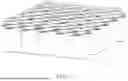
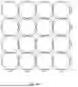
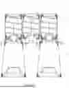
FIG. 11 is a schematic view of the first springs being assembled in Embodiment 1.
FIG. 12 is a schematic view of the second spring mounted on the first spring in Embodiment 1.
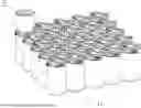
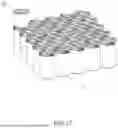
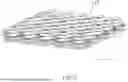
FIG. 13 is a schematic view of a partial elastic module formed by the first springs and the second springs in Embodiment 1.
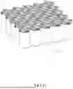
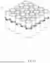
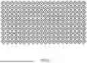
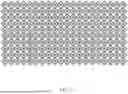
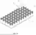
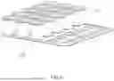
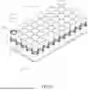
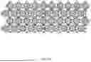
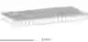
FIG. 14 is a schematic view of an elastic module in Embodiment 1.
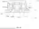
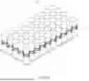
FIG. 15 is a schematic view of an elastic cushion in Embodiment 1.
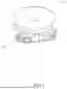
FIGS. 16-18 are schematic views of an assembly method where the second spring is installed first, followed by assembly into a structure shown in FIG. 14.
FIGS. 19-22 are schematic views of an assembly method where the first spring is assembled first, followed by installation of the second spring.
FIG. 23 is a schematic view of a spring unit in Embodiment 2.
FIG. 24 is an exploded view of the spring unit in Embodiment 2.
FIG. 25 is a cross-sectional view of a first spring in a compressed state in Embodiment 2.
FIG. 26 is a cross-sectional view of the first spring in Embodiment 2.
FIG. 27 is a schematic view of a first spring in Embodiment 3.
FIG. 28 is a schematic view of the first spring in a compressed state in Embodiment 3.
FIG. 29 is a cross-sectional view of the first spring in the compressed state in Embodiment 3.
FIG. 30 is a schematic view of a second spring in Embodiment 3.
FIG. 31 is a cross-sectional view of the second spring in Embodiment 3.
FIG. 32 is a schematic view of the first springs in the compressed state in Embodiment 3, when the first springs are assembled together.
FIG. 33 is a schematic view of the first springs in a released state in Embodiment 3, when the first springs are assembled together.
FIG. 34 is a schematic view of the second spring mounted on the first spring in Embodiment 3.
FIG. 35 is a schematic view of an elastic module in Embodiment 3.
FIG. 36 is a schematic view of first springs in a compressed state in Embodiment 4.
FIG. 37 is a schematic view of the first springs in a released state in Embodiment 4.
FIG. 38 is a schematic view of second springs mounted on a connecting plate in Embodiment 4.
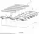
FIG. 39 is a schematic view of an elastic module in an assembly process in Embodiment 4.
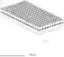
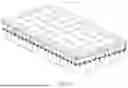
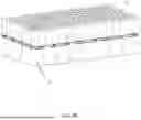
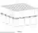
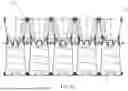
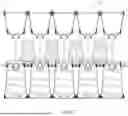
FIG. 40 is a schematic view of an elastic module in Embodiment 5.
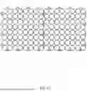
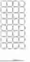
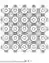
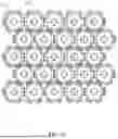
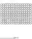
FIG. 41 is a top view of the elastic module in Embodiment 5.
FIG. 42 is a bottom view of the elastic module in Embodiment 5.
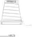
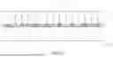
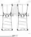
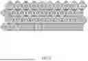
FIG. 43 is a side view (long edge) of the elastic module in Embodiment 5.
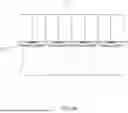
FIG. 44 is a side view (short edge) of the elastic module in Embodiment 5.
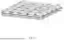
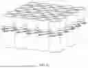
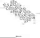
FIG. 45 is a schematic view of a disassembled partial elastic module in Embodiment 5.
FIG. 46 is a bottom view of the disassembled partial elastic module in Embodiment 5.
FIG. 47 is a top view of the disassembled partial elastic module in Embodiment 5.
FIG. 48 is a cross-sectional view of a group of spring units in a disassembled state in Embodiment 6.
FIG. 49 is a top view of the group of spring units in the assembled state in Embodiment 6.
FIG. 50 is a cross-sectional view of an elastic module in Embodiment 6.
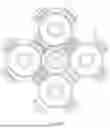
FIG. 51 is a schematic view of an installation position of a third spring in Embodiment 6.
FIG. 52 is a cross-sectional view of the group of spring units in the assembled state in Embodiment 6.
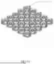
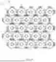
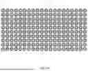
FIG. 53 is a top view of the elastic module in Embodiment 6.
FIG. 54 is an exploded view of a spring unit in Embodiment 7.
FIG. 55 is a schematic view of an elastic module in Embodiment 7.
FIGS. 56-60 are schematic views of arrangements of spring units in an elastic module of Embodiment 8.
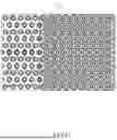
FIG. 61 is a distribution schematic of first springs in Embodiment 9.
FIG. 62 is a distribution schematic of second springs in Embodiment 9.
FIG. 63 is a cross-sectional view of a connection between second springs and a third spring in Embodiment 10.
FIG. 64 is a top view of a connection between the second springs and the third spring in Embodiment 10.
FIG. 65 is a schematic view of a lower elastic layer formed by assembled first springs in Embodiment 10.
FIG. 66 is a top view of the lower elastic layer formed by the assembled first springs in Embodiment 10.
FIG. 67 is a schematic view of an elastic module in Embodiment 10.
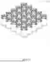
FIG. 68 is a top view of the elastic module in Embodiment 10.
DETAILED DESCRIPTION OF THE EMBODIMENTS
The following will clearly and completely describe the technical solutions in the embodiments of the present disclosure with reference to the accompanying drawings. Obviously, the described embodiments are only a portion of the embodiments of the present disclosure, and not all of the embodiments. Based on the embodiments of the present disclosure, all other embodiments obtained by those of ordinary skill in the art without creative work fall within the protection scope of the present disclosure.
In the description of the present disclosure, it should be noted that the terms “upper”, “lower”, “inner”, “inner”, “outer”, “top end”, “bottom end”, etc. indicate the orientation or positional relationship based on the orientation shown in the drawings. The positional relationship is only for the convenience of describing the present disclosure and simplifying the description, rather than indicating or implying that the referenced device or element must have a specific orientation, be constructed, and be operated in a specific orientation. Therefore, the positional relationship should not be understood as a limitation of the present disclosure. Additionally, the terms “first” and “second” are used solely for descriptive purposes and should not be construed as indicating or implying relative importance.
In the description of the present disclosure, it is noted that unless otherwise explicitly defined or limited, terms such as “mounted,” “provided with,” “sleeved”, “fitted,” and “connected” shall be interpreted broadly. For example, “connected” may refer to wall-mounted connections, detachable connections, integral connections, mechanical connections, or electrical connections. It may involve direct attachment, indirect linkage via an intermediary medium, or internal communication between two components. To those of ordinary skill in the art, the specific meanings of these terms in the context of the present disclosure may be understood based on practical circumstances.
Embodiment 1
Referring to FIGS. 1 to 22, an elastic module is provided in this embodiment, and the elastic module comprises a plurality of spring units 1. Each of the plurality of spring units 1 comprises a first spring 11 and a second spring 12, and the first spring 11 is configured to be axially compressed to a locking position due to an external force.
Specifically, the first spring 11 comprises a spring 111, a cloth cover 112, and an end cover 113, which are similar to those disclosed in Embodiment 2. The cloth cover 112 is wrapped on an outside of the spring 111. The end cover 113 is installed on a top of the spring 111 and an outside of the cloth cover 112 to enable the cloth cover 112 to be fixed to form a pocket spring. All sides of the end cover 113 comprise a plurality of connecting structures 114, and adjacent ones of the first springs 11 of the plurality of spring units 1 are configured to be spliced together through the plurality of connecting structures 114. The second spring 12 comprises a bottom cover 121, and the bottom cover 121 of the second spring 12 is detachably connected to the end cover 113 through a mounting structure on the end cover 113, so that the second spring 12 is installed on the first spring 11 to form a corresponding one of the plurality of spring units 1. The plurality of spring units 1 are spliced together through the plurality of connecting structures 114 on the all sides of the first spring 11 to form the elastic module.
During a splicing process, the first springs 11 of the plurality of spring units 1 can be released and then spliced together to form a lower elastic layer, and then the second springs 12 of the plurality of spring units 1 can be installed on the first springs 11 to form an upper elastic layer. The upper elastic layer and the lower elastic layer together form the elastic module. The second springs 12 can also be installed on the first springs 11 to form the plurality of spring units 1 and then the plurality of spring units 1 are spliced through the plurality of connecting structures 114 on the first spring 11. The elastic module can also be divided into the upper elastic layer formed by the first springs 11 and the lower elastic layer formed by the second springs 12. The first springs 11 can also be spliced together in a compressed state to form the lower elastic layer in a compressed state, and then the lower elastic layer can be released and the second springs 12 can be installed to form the elastic module.
In this embodiment, the bottom cover 121 of the second spring 12 is connected to the end cover 113 of the first spring 11 by rotation. The bottom cover 121 of the second spring 12 is symmetrically provided with two rotation-connecting members 122, and each of the two rotation-connecting members 122 comprises a first part 1221 and a second part 1222. The first part 1221 extends axially from a bottom of a base, and the second part 1222 is located at an end of the first part 1221 and extends radially outward from a center of the first part 1221. A top of the end cover 113 comprises two sliding rails 1131 corresponding to the two rotation-connecting members 122 in a one-to-one correspondence as the mounting structure, and each of the two sliding rails 1131 is a strip-shaped recessed hole. A width of the strip-shaped recessed hole gradually narrows along a rotation direction of the two rotation-connecting members 122. A width of a narrowest part of the strip-shaped recessed hole is smaller than a width of the second part 1222.
The two rotation-connecting members 122 of the second spring 12 are inserted into the strip-shaped recessed hole and then the second spring 12 is rotated until the second part 1222 of each of the two rotation-connecting members 122 is rotated to the narrowest part of the strip-shaped recessed hole. Since the width of the narrowest part of the strip-shaped recessed hole is smaller than the width of the second part 1222, the second part 1222 of each of the two rotation-connecting members 122 and the strip-shaped recessed hole are axially interlocked with each other, so that the second spring 12 is installed on an upper side of the first spring 11. When the second spring needs to be detached, the second spring 12 is rotated until the second part 1222 of each of the two rotation-connecting members 122 reaches a wide part of the strip-shaped recessed hole so that the two rotation-connecting members 122 can be taken out from the wide part.
As a simple alternative to the present embodiment, the bottom cover 121 of the second spring 12 is connected to the end cover 113 of the first spring 11 by insertion. A bottom of the bottom cover 121 comprises a conical insertion member 123 with a gradually decreasing radius along an insertion direction of the conical insertion member 123, and the top of the end cover 113 comprises an insertion groove 1132 configured to correspond to the conical insertion member 123. The conical insertion member 123 is inserted into the insertion groove 1132 to enable the conical insertion member 123 to be self-locked along a vertical direction. The conical insertion member 123 of the second spring 12 is inserted into the insertion groove 1132 on the end cover 113 of the first spring 11, and the conical insertion member 123 is self-locked in the insertion groove 1132 so that the second spring 12 is installed on the upper side of the first spring 11. When the second spring 12 needs to be detached, the conical insertion member 123 of the second spring 12 can be pulled out from the insertion groove 1132 on the end cover 113 of the first spring 11 by an external force.
To facilitate storage of the second spring 12, the second spring 12 can be compressed to a locked position along an axial direction of the second spring 12 due to an external force. A locking method for the first spring 11 and the second spring 12 to be in the compressed state is not limited, as long as a purpose of this embodiment can be achieved. An upper end and a lower end of the first spring 11 can be installed with a buckling structure, and the compressed state of the first spring 11 is achieved by the buckling structures, or any method in the existing techniques can be adopted.
When the elastic module needs to be disassembled for storage or transportation, the plurality of spring units 1 assembled to form the elastic module are first disassembled, and then the first spring 11 and the second spring 12 of each of the plurality of the spring units 1 are disassembled according to the above method. The first spring 11 and the second spring 12 are respectively compressed to the locked state by an external force, and a space occupied by the first spring 11 and the second spring 12 when compressed to the locked state is significantly reduced compared to when not compressed. Compared with a traditional elastic module, each of the plurality of spring units 1 of the elastic module in this embodiment can be disassembled independently, and each of the plurality of spring units 1 can also be disassembled into the first spring 11 and the second spring 12. The first spring 11 and the second spring 12 can be compressed to the locked state. Therefore, when carrying, transporting, or storing, each of the plurality of spring units 1 is split into the first spring 11 and the second spring 12 in a smallest compressed state, which can reduce an occupied space, facilitate manual handling, and increase a number of the plurality of spring units 1 carried at one time, thereby improving transportation efficiency.
When the plurality of spring units 1 need to be assembled into the elastic module, the first spring 11 and the second spring 12 are released, and then the first springs 11 are assembled into the lower elastic layer through the plurality of connecting structures 114. Then, the second springs 12 are installed one by one on the first springs 11 to form the upper elastic layer, and the upper elastic layer and the lower elastic layer together form the elastic module. Alternatively, the first spring 11 and the second spring 12 can be assembled directly into a single one of the plurality of spring units 1 after releasing the first spring 11 and the second spring 12, and then the plurality of spring units 1 can be assembled into the elastic module through the plurality of connecting structures 114.
As a simple alternative to the present embodiment, the second spring 12 is a hollow structure, and the second springs 12 can be axially stacked. Therefore, when the elastic module is disassembled into the first springs 11 and the second springs 12, the first springs 11 are compressed to the locked state, and then the second springs 12 are axially stacked, which can also reduce the occupied space.
In order to meet the needs of different users for an elastic cushion with different hardness and softness, springs in the second springs 12 forming the upper elastic layer are detachable, so that the springs can be replaced with different hardness and softness according to user needs.
The elastic cushion can be formed by laying a cushion layer 4 on the upper elastic layer of the elastic module of this embodiment.
Embodiment 2
Referring to FIGS. 23 to 26, an elastic module is provided in this embodiment, and the elastic module comprises a plurality of spring units 1. Each of the plurality of spring units 1 comprises a first spring 11 and a second spring 12, and the first spring 11 is configured to be axially compressed to a locking position.
Specifically, the first spring 11 comprises a spring 111, a cloth cover 112, and an end cover 113. The cloth cover 112 is wrapped on an outside of the spring 111. The end cover 113 is installed on a top of the spring 111 and an outside of the cloth cover 112 to enable the cloth cover 112 to be fixed to form a pocket spring. All sides of the end cover 113 comprise a plurality of connecting structures 114, and adjacent ones of the first springs 11 of the plurality of spring units 1 are configured to be spliced together through the plurality of connecting structures 114. The second spring 12 comprises a bottom cover 121, and the bottom cover 121 of the second spring 12 is detachably connected to the end cover 113 through a mounting structure on the end cover 113, so that the second spring 12 is installed on the first spring 11 to form a corresponding one of the plurality of spring units 1. The plurality of spring units 1 are spliced together through the plurality of connecting structures 114 on the all sides of the first spring 11 to form the elastic module.
In this embodiment, the bottom cover 121 of the second spring 12 is connected to the end cover 113 of the first spring 11 by insertion. A bottom of the bottom cover 121 is symmetrically provided with two tapered insertion members 124 with a gradually decreasing width, and a tapered groove 125 is formed between the two tapered insertion members 124. Two sides of a top of the end cover 113 comprises two tapered insertion grooves 1133 configured to cooperate with the two tapered insertion members 124, and a tapered protrusion 1137 is formed between the two tapered insertion grooves 1133. The two tapered insertion members 124 are inserted into the two tapered insertion grooves 1133, and a double-conical surface structure formed by the two tapered insertion members 124 and the tapered protrusion 1137 is self-locked along a vertical direction. The two tapered insertion members 124 of the second spring 12 are inserted into the two tapered insertion grooves 1133 of the first spring 11, so that the second spring 12 is installed on the first spring 11.
In this embodiment, a base 115 is further provided at a second end of the first spring 11. Two hooks 1134 are symmetrically provided on a lower end surface of the end cover 113 in a compression direction as a first buckling structure. Each of the two hooks 1134 comprises a connecting portion 11341 and a hook portion 11342. The hook portion 11342 is disposed on an outer side of the connecting portion 11341. Two sides of the base 115 extend toward a center of the base 115 to form two buckling members 1151 as a second buckling structure. Each of the two buckling members 1151 comprises a connecting arm 11511 and a buckling portion 11512. The buckling portion 11512 is located at a distal end of the connecting arm 11511. The buckling portion 11512 is suspended so that the two buckling members 1151 have elasticity to be pushed up by the two hooks 1134. A distance between the buckling portion 11512 and a central axis of the first spring 11 gradually decreases along the compression direction of the spring 111, so that the buckling portion 11512 forms an inclined surface. Due to an external force, the hook portion 11342 slides down along the inclined surface to be buckled to a bottom end of the buckling portion 11512, so that the two hooks 1134 and the two buckling members 1151 are axially interlocked with each other to realize locking of the first spring 11. When the first spring 11 is in the locking position, the hook portion 11342 and the buckling portion 11512 are axially interlocked with each other to achieve a buckling connection.
The end cover 113 and the base 115 are grabbed with both hands, and then the first spring 11 is compressed in an axial direction of the first spring 11. Due to an external force, the hook portion 11342 slides down along the inclined surface to be buckled to the bottom end of the buckling portion 11512, so that the two hooks 1134 and the two buckling members 1151 are axially interlocked with each other to achieve the locking of the first spring 11. When the first spring 11 needs to be released, the end cover 113 and the base 115 are pulled outward. At this time, the hook portion 11342 pushes the buckling portion 11512 until the hook portion 11342 is separated from the buckling portion 11512 to release the buckling connection. The first spring 11 will be released due to a reset force of the spring 111. The locking and releasing method of the first spring 11 in a compressed state in this embodiment can be applied to the above-mentioned embodiment, and can also be applied to the second spring 12.
In this embodiment, the end cover 113 and the base 115 of the first spring 11 are detachably mounted on the spring 111. Specifically, the outside of the cloth cover 112 at the top of the spring 111 is disposed with a ring 1121. A lower surface of the ring 1121 is recessed inward along the vertical direction to form an annular groove 11213. A bottom end of the end cover 113 is disposed with a positioning structure 11311, and the positioning structure 11311 is buckled to the annular groove 11213 to be interlocked with the ring 1121. The ring 1121 comprises a first portion 1223 and a second portion 1224. The second portion 1224 is disposed on an inside of the cloth cover 112, and the first portion 1223 is disposed on the outside of the cloth cover 112. The first portion 1223 and the second portion 1224 are buckled and fixed to the cloth cover 112. The ring 1121 enables the cloth cover 112 wrapped on the outside of the spring 111 to be fixed, and the ring 1121 cooperates with the end cover 113 to be interlocked with the end cover 113 so that the end cover 113 is installed on the top of the first spring 11.
Alternatively, the outside of the cloth cover 112 at a bottom of the spring 111 is disposed with another one of the rings 1121, and an outside of the ring 1121 comprises a protrusion 1122. A radial outside of the base 115 forms a U-shaped groove 1153, a top of an outer wall of the U-shaped groove 1153 forms another one of the positioning structures 11311, and the ring 1121 is buckled to the U-shaped groove 1153. The U-shaped groove 1153 and the ring 1121 are axially interlocked with each other. The ring 1121 also comprises a first portion 11211 and a second portion 11212, and the second portion 11212 is disposed on the inside of the cloth cover 112. The first portion 11211 is disposed on the outside of the cloth cover 112, and the first portion 11211 and the second portion 11212 are buckled and fixed to the cloth cover 112.
The rest is the same as that of Embodiment 1 and will not be repeated.
Embodiment 3
Referring to FIGS. 27 to 35, an elastic module is provided in this embodiment, and the elastic module comprises a plurality of spring units 1. Each of the plurality of spring units 1 comprises a first spring 11 and a second spring 12, and the first spring 11 is configured to be axially compressed to a locking position.
Specifically, the first spring 11 comprises a spring 111, a cloth cover 112, and an end cover 113. The cloth cover 112 is wrapped on an outside of the spring 111. The end cover 113 is installed on a top of the spring 111 and an outside of the cloth cover 112 to enable the cloth cover 112 to be fixed to form a pocket spring. All sides of the end cover 113 comprise a plurality of connecting structures 114, and adjacent ones of the first springs 11 of the plurality of spring units 1 are configured to be spliced together through the plurality of connecting structures 114. The second spring 12 comprises a bottom cover 121, and the bottom cover 121 of the second spring 12 is detachably connected to the end cover 113 through a mounting structure on the end cover 113, so that the second spring 12 is installed on the first spring 11 to form a corresponding one of the plurality of spring units 1. The plurality of spring units 1 are spliced together through the plurality of connecting structures 114 on the all sides of the first spring 11 to form the elastic module.
In this embodiment, the bottom cover 121 of the second spring 12 is threadedly connected to the end cover 113 of the first spring 11. An inside of the end cover 113 comprises a threaded connecting member 1139, and outer threads 11391 are provided on an outer wall of the threaded connecting member 1139. The bottom cover 121 is a circular ring, and an inner wall of the circular ring is provided with inner threads 11392. The bottom cover 121 of the second spring 12 is threadedly connected to the threaded connecting member 1139. The threaded connecting member 1139 of the end cover 113 is inserted into the circular ring of the bottom cover 121, and then the end cover 113 is rotated to enable the inner threads 11392 on the inner wall of the circular ring and the outer threads 11391 on the outer wall of the threaded connecting member 1139 to be threadedly matched. After tightening, the second spring 12 is installed on the first spring 11.
In this embodiment, a lower end surface of the end cover 113 is disposed with a pushing member 1135 extending along a compression direction of the first spring 11, and two sides of the pushing member 1135 are respectively disposed with one or more elastic position-limiting members 1136 as a first buckling structure. An upper end surface of a base 115 is disposed with a position-limiting groove 1152 configured to cooperate with the one or more elastic position-limiting members 1136 as a second buckling structure. A side wall of the position-limiting groove 1152 is formed with a position-limiting wall 11521. Due to an external force, the pushing member 1135 drives the one or more elastic position-limiting members 1136 to slide into the position-limiting groove 1152 to enable the one or more elastic position-limiting members 1136 to contact the position-limiting wall 11521, until a friction between the one or more elastic position-limiting members 1136 and the position-limiting wall 11521 is greater than a restoring force of the spring 111, so that the one or more elastic position-limiting members 1136 are stuck by the position-limiting wall 11521 to achieve a buckling connection. The rest is the same as that of Embodiment 1 and will not be repeated.
Embodiment 4
Referring to FIGS. 36 to 39, this embodiment provides an elastic module, and the elastic module comprises a plurality of spring units 1. Each of the plurality of spring units 1 comprises a first spring 11 and a second spring 12.
A top of the first spring 11 comprises an end cover 113, and all sides of the end cover 113 comprise a plurality of connecting structures 114. Adjacent ones of the first springs 11 of the plurality of spring units 1 are configured to be spliced together through the plurality of connecting structures 114. The first spring 11 is configured to be axially compressed to a locking position. A bottom of the second spring 12 comprises a bottom cover 121. The elastic module comprises a connecting plate 2. An upper side and a lower side of the connecting plate 2 each comprises a plurality of circular protruding rings 21 extending along a vertical direction as a first insertion structure and a second insertion structure, and the plurality of circular protruding rings 21 are arranged in an array on the connecting plate 2. An upper end surface of the end cover 113 of the first spring 11 and a lower end surface of the bottom cover 121 of the second spring 12 each comprises a recessed hole that is interference-fitted with a corresponding one of the plurality of circular protruding rings 21, and each of the plurality of circular protruding rings 21 has a certain interference amount relative to the recessed hole of the end cover 113 and the recessed hole of the bottom cover 121.
When splicing the elastic module, the plurality of circular protruding rings 21 of the connecting plate 2 are respectively inserted into the recessed hole of the first spring 11 and the recessed hole of the second spring 12, so that the first spring 11 and the second spring 12 are spliced into a single one of the plurality of spring units 1. The plurality of spring units 1 are spliced to form the elastic module through the plurality of connecting structures 114 on all sides of the first spring 11. The first springs 11 form a lower elastic layer on the lower side of the connecting plate 2, and the second springs 12 form an upper elastic layer on the upper side of the connecting plate 2. A cushion layer is laid on the upper elastic layer to form an elastic cushion. The rest is the same as that of Embodiment 1 and will not be repeated here.
Embodiment 5
Referring to FIGS. 40-47, this embodiment provides an elastic module, and the elastic module comprises a plurality of spring units 1. The plurality of spring units 1 are spliced together to form the elastic module. Each of the plurality of spring units 1 comprises a first spring 11 and four second springs 12, and the first spring 11 can be axially compressed to a locking position. An upper end of the first spring 11 comprises an end cover 113, and the four second springs 12 can be detachably mounted on the end cover 113 to form a corresponding one of the plurality of spring units 1.
The difference between this embodiment and Embodiment 1 is the four second springs 12, and a diameter of each of the four second springs 12 is smaller than a diameter of the first spring 11, so that the four second springs 12 can be installed on the end cover 113 of the first spring 11, thereby increasing a number of springs in an upper elastic layer and making an elastic cushion using the elastic module of this embodiment more comfortable. Taking the elastic cushion of 1 meter by 2 meters as an example, a total number of the four second springs 12 in the upper elastic layer can be increased by more than 300%. A number of the second springs 12 can be improved according to the needs of the user and is not limited to 4 in this embodiment. The rest is the same as that of Embodiment 1 and will not be repeated here.
Embodiment 6
Referring to FIGS. 48-53, this embodiment provides an elastic module, and the elastic module comprises a plurality of spring units 1. Each of the plurality of spring units 1 comprises a first spring 11 and a second spring 12, and the first spring 11 can be axially compressed to a locking position. An upper end of the first spring 11 comprise an end cover 113, and the second spring 12 can be detachably mounted on the end cover 113. The plurality of spring units 1 are arranged in a transverse and longitudinal array so that a gap is formed between each four adjacent spring units 1 of the plurality of spring units 1. A position of the gap corresponding to the second springs 12 is disposed with a third spring 13 to form the elastic module.
The difference between this embodiment and Embodiment 1 is that in this embodiment, the third springs 13 are inserted into an upper elastic layer formed by the second springs 12. Since the second spring 12 is in an inverted cone shape, when the second spring 12 is arranged in the transverse and longitudinal array, a space is formed and surrounded by each four second springs 12 of the second springs 12 for a positive conical spring to be disposed. Therefore, the third spring 13 having a positive conical shape and disposed in the space to increase a number of supporting points of the upper elastic layer can make an elastic cushion using the elastic module of this embodiment more comfortable. Taking the elastic cushion of 1 meter by 2 meters as an example, a total number of the second springs 12 and the third springs 13 in the upper elastic layer can be increased by more than 80% compared with Embodiment 1. The rest is the same as that of Embodiment 1 and Embodiment 2 and will not be repeated.
Embodiment 7
Referring to FIGS. 54-55, when the second spring 12 is a hollow structure, a contact surface between a user and the second spring 12 is only an annular contact area, which is small and hard, and a thick cushion layer is required to improve comfort of an elastic cushion so that the user cannot feel the annular contact area. When a cushion layer is thin, the elastic cushion will be very uncomfortable.
Therefore, to improve elastic touch and comfort of the elastic cushion, in this embodiment, a flexible spring top cover 14 is provided on an upper side of the second spring 12, and the flexible spring top cover 14 is inserted into the hollow structure, which can increase a contact surface between the user and the second spring 12. At the same time, a spring 129 inside the flexible spring top cover 14 has high elasticity and a flexible upper end, which can improve the elastic touch and comfort.
Embodiment 8
The difference between this embodiment and Embodiment 1 is that the plurality of connecting structures 114 in Embodiment 1 are symmetrically arranged on all sides of the end cover 113, so that the plurality of spring units 1 are connected to each other in a transverse direction and a longitudinal direction to enable the plurality of spring units 1 to be arranged in a matrix arrangement.
In this embodiment, two adjacent rows of the plurality of spring units 1 are arranged in a staggered arrangement to form a hexagonal distribution, which increases a number of springs per unit area and reduces a spring gap of a quadrilateral layout. The number of the springs can be increased by more than 15%, which greatly improve comfort of the elastic cushion.
In order to form the staggered arrangement, an arrangement of the plurality of connecting structures 114 is different from Embodiment 1, and the following methods may be used.
-
- 1. In Embodiment 1, a number of the plurality of connecting structures 114 is identical in both transverse and longitudinal directions, with one structure on each side. However, as shown in FIG. 56, in this embodiment, each side of the end cover 113 in the longitudinal direction is provided with two connecting structures 114 of the plurality of connecting structures 114 for connecting corresponding ones of the plurality of the spring units 1 in the longitudinal direction, and the two connecting structures 114 are arranged in an equilateral triangle configuration (i.e., the two connecting structures 114 are spaced at 60-degree intervals).
- 2. As shown in FIG. 57, in this embodiment, the plurality of connecting structures 114 for connecting the corresponding ones of the plurality of the spring units 1 in the longitudinal direction are divided into a first portion 1141 on a first longitudinal side between adjacent two spring units 1 of the plurality of the spring units 1 and a second portion 1142 on a second longitudinal side of a corresponding one of the plurality of spring units 1. Two adjacent rows of the plurality of spring units 1 can be arranged in a staggered arrangement to form a hexagonal distribution by connecting the first portion 1141 and the second portion 1142. FIG. 58 and FIG. 59 are simple variations of FIG. 57 and will not be described in detail.
- 3. As shown in FIG. 60, the plurality of connecting structures 114 on a first row of the plurality of spring units 1 for connecting the first row of the plurality of spring units 1 in the longitudinal direction in this embodiment are first parts 1141, and the plurality of connecting structures 114 on a second row of the plurality of spring units 1 adjacent to the first row of the plurality of spring units 1 are second parts 1142. The first parts 1141 are located on two sides of each of the plurality of spring units 1 along the longitudinal direction. The second parts 1142 are located on two sides of each of the plurality of spring units 1 along the longitudinal direction.
Embodiment 9
In Embodiment 8, the plurality of spring units 1 are hexagonally distributed. That is, the first spring 11 and the second spring 12 are both hexagonally distributed. Since the second spring 12 contacts a human body, increasing in a number of the first springs 11 has limited effect on improving comfort of an elastic cushion and increases a cost.
Therefore, for a solution with the connecting plate 2 in Embodiment 4, the first spring 11 and the second spring 12 are connected to the connecting plate 2 respectively through the first insertion structure and the second insertion structure. Therefore, as long as a distribution of the first insertion structure and the second insertion structure on the connecting plate 2 is changed to be different, a distribution of the first springs 11 and a distribution of the second springs 12 can be changed to be different. For example, in this embodiment, as shown in FIGS. 61 and 62, the first insertion structure is distributed in an array, so that the first springs 11 are arranged in a matrix arrangement. The second insertion structure is in a staggered arrangement on two adjacent rows of the plurality of spring units 1, so that the second springs 12 are distributed in a hexagonal shape. In this way, the number of the second springs 12 can be increased separately, which can reduce the cost and greatly improve the comfort of the elastic cushion.
Embodiment 10
In Embodiment 6, the third spring 13 with the positive conical shape is placed between the second springs 12, the second springs 12 are in the inverted conical shape, and the third spring 13 is in the positive conical shape. When the upper elastic layer is compressed, a force value and a force direction on the second spring 12 and the third spring 13 are inconsistent. Especially, when a volume of the third spring 13 is smaller than a volume of the second spring 12, an uneven force will reduce comfort of an elastic cushion. Therefore, the second spring 12 and the third spring 13 in the upper elastic layer need to be evenly stressed while maintaining density, thereby maintaining the comfort of the elastic cushion.
Referring to FIGS. 63-68, in this embodiment, the second spring 12 and the third spring 13 are cylindrical and have a same size. A size of the second spring 12 is slightly smaller than the first spring 11, so that a space that can accommodate the third spring 13 can be formed after splicing. The second spring 12 and the third spring 13 are of the same size and cylindrical. When the upper elastic layer is compressed, the second spring 12 and the third spring 13 are subjected to a same force direction and a same force value.
The aforementioned embodiments are merely some embodiments of the present disclosure, and the scope of the disclosure is not limited thereto. Thus, it is intended that the present disclosure cover any modifications and variations of the presently presented embodiments provided they are made without departing from the appended claims and the specification of the present disclosure.
Claims
What is claimed is:1. An elastic module, comprising:
a plurality of spring units, wherein:
the plurality of spring units are configured to be spliced together to form the elastic module,
each of the plurality of spring units comprises a first spring and a second spring,
the first spring is configured to be axially compressed to a locking position,
an upper end of the first spring is disposed with an end cover, and
the second spring is detachably connected to the end cover to form a corresponding one of the plurality of spring units.
2. The elastic module according to claim 1, wherein:
a bottom of the second spring is disposed with a bottom cover, and
the bottom cover of the second spring is connected to the end cover by rotation, insertion, or threads.
3. The elastic module according to claim 2, wherein:
the bottom cover of the second spring is symmetrically provided with two rotation-connecting members,
each of the two rotation-connecting members comprises a first part and a second part,
the first part extends axially from a bottom of a base, and
the second part is located at an end of the first part and extends radially outward from a center of the first part.
4. The elastic module according to claim 3, wherein:
a top of the end cover comprises two sliding rails corresponding to the two rotation-connecting members in a one-to-one correspondence as a mounting structure,
each of the two sliding rails is a strip-shaped recessed hole,
a width of the strip-shaped recessed hole gradually narrows along a rotation direction of the two rotation-connecting members, and
a width of a narrowest part of the strip-shaped recessed hole is smaller than a width of the second part.
5. The elastic module according to claim 2, wherein:
a bottom of the bottom cover of the second spring is disposed with an insertion member.
6. The elastic module according to claim 5, wherein:
a top of the end cover of the first spring comprises an insertion groove configured to correspond to the insertion member.
7. The elastic module according to claim 6, wherein:
the bottom of the bottom cover of the second spring is disposed with a conical insertion member with a gradually decreasing radius along an insertion direction of the conical insertion member, and
the conical insertion member is configured to be inserted into the insertion groove to enable the conical insertion member to be self-locked along a vertical direction.
8. The elastic module according to claim 6, wherein:
the bottom of the bottom cover is symmetrically provided with two tapered insertion members with a gradually decreasing width along an insertion direction of the two tapered insertion members,
a tapered groove is formed between the two tapered insertion members,
two sides of the top of the end cover comprise two tapered insertion grooves configured to cooperate with the two tapered insertion members,
a tapered protrusion is formed between the two tapered insertion grooves,
the two tapered insertion members are configured to be inserted into the two tapered insertion grooves, and
a double-conical surface structure formed by the two tapered insertion members and the tapered protrusion is self-locked along a vertical direction.
9. The elastic module according to claim 2, wherein:
an inside the end cover comprises a threaded connecting member,
outer threads are provided on an outer wall of the threaded connecting member,
the bottom cover is a circular ring,
an inner wall of the circular ring is provided with inner threads, and
the bottom cover of the second spring is threadedly connected to the threaded connecting member.
10. The elastic module according to claim 1, wherein:
the plurality of spring units are arranged in a staggered arrangement to form a hexagonal distribution.
11. An elastic module, comprising:
a plurality of spring units, and
a connecting plate, wherein:
the plurality of spring units are configured to be spliced together to form the elastic module,
each of the plurality of spring units comprises a first spring and a second spring,
the first spring is configured to be axially compressed to a locking position,
an upper end of the first spring is disposed with an end cover,
a bottom of the second spring is disposed with a bottom cover, and
the end covers of the first springs of the plurality of spring units and the bottom covers of the second springs of the plurality of spring units are respectively connected to two sides of the connecting plate to form the elastic module.
12. The elastic module according to claim 11, wherein:
a lower side of the connecting plate comprises a first insertion structure into which the end cover of the first spring is inserted, and
an upper side of the connecting plate comprises a second insertion structure into which the bottom cover of the second spring is inserted.
13. The elastic module according to claim 12, wherein:
the first springs of the plurality of spring units are arranged in a transverse direction and a longitudinal direction to be in a matrix arrangement, or
the first springs of the plurality of spring units are arranged in a staggered arrangement to form a hexagonal distribution.
14. The elastic module according to claim 12, wherein:
the second springs of the plurality of spring units are arranged in a transverse direction and a longitudinal direction to be in a matrix arrangement, or
the second springs of the plurality of spring units are arranged in a staggered arrangement to form a hexagonal distribution.
15. The elastic module according to claim 12, wherein:
the upper side and the lower side of the connecting plate each comprises a plurality of circular protruding rings extending along a vertical direction, and
the end cover and the bottom cover each comprises a recessed hole that is interference-fitted with a corresponding one of the plurality of circular protruding rings.
16. The elastic module according to claim 12, wherein:
the upper side and the lower side of the connecting plate are each formed with a plurality of annular insertion grooves, and
an inside of each of the plurality of annular insertion grooves comprises a tapered insertion member configured to be connected to the bottom cover or the end cover to be self-locked along an axial direction of the first spring.
17. An elastic module, comprising:
a plurality of spring units, wherein:
each of the plurality of spring units comprises a first spring and a second spring,
the first spring is configured to be axially compressed to a locking position,
an upper end of the first spring is disposed with an end cover,
the second spring is detachably connected to the end cover,
the plurality of spring units are arranged in a transverse direction and a longitudinal direction to be in a matrix arrangement to enable adjacent rows or columns of the plurality of spring units to be formed with gaps, and
one or more third springs are inserted into one or more of the gaps to form the elastic module.
18. The elastic module according to claim 17, wherein:
the second spring is in an inverted conical shape, and
the one or more third springs are in a positive conical shape.
19. The elastic module according to claim 18, wherein:
the second spring and the one or more third springs are cylindrical and have a same size.
20. An elastic module, comprising:
a plurality of spring units, wherein:
the plurality of spring units are configured to be spliced together to form the elastic module,
each of the plurality of spring units comprises a first spring and at least two second springs,
the first spring is configured to be axially compressed to a locking position,
an upper end of the first spring is disposed with an end cover, and
the at least two second springs are detachably connected to the end cover to form a corresponding one of the plurality of spring units.
21. The elastic module according to claim 20, wherein:
the end cover comprises at least two mounting structures, and
the at least two second springs are connected to the end cover through the at least two mounting structures by insertion or rotation.
22. The elastic module according to claim 1, wherein:
the second spring is configured to be axially compressed to a locking position.
23. The elastic module according to claim 1, wherein:
the second spring is a hollow structure, and
the second springs of the plurality of spring units are configured to be stacked to each other along an axial direction of the second springs.
24. The elastic module according to claim 23, wherein:
a flexible spring top cover is provided on an upper side of the second spring, and
the flexible spring top cover is inserted into the hollow structure.
25. The elastic module according to claim 1, wherein:
an end of the first spring facing the end cover is disposed with a base,
a lower end of the end cover is disposed with a first buckling structure extending along a spring compression direction,
an upper end of the base is disposed with a second buckling structure extending along the spring compression direction, and
when the first spring is in the locking position, the first buckling structure and the second buckling structure are buckled to each other.
26. The elastic module according to claim 25, wherein:
two hooks are symmetrically provided on a lower end surface of the end cover in the spring compression direction as the first buckling structure,
each of the two hooks comprises a connecting portion and a hook portion, and
the hook portion is disposed on an outer side of the connecting portion.
27. The elastic module according to claim 26, wherein:
two sides of the base extend toward a center of the base to form two buckling members as the second buckling structure,
each of the two buckling members comprises a connecting arm and a buckling portion,
the buckling portion is located at a distal end of the connecting arm,
the buckling portion is suspended so that the two buckling members have elasticity to be pushed up by the two hooks, and
when the first spring is in the locking position, the hook portion and the buckling portion are axially interlocked with each other to achieve a buckling connection.
28. The elastic module according to claim 27, wherein:
a distance between the buckling portion and a central axis of the first spring gradually decreases along the spring compression direction of the first spring, so that the buckling portion forms an inclined surface, and
due to an external force, the hook portion slides down along the inclined surface to be buckled to a bottom end of the buckling portion, so that the two hooks and the two buckling members are axially interlocked with each other.
29. The elastic module according to claim 28, wherein:
due to the external force, the hook portion pushes the buckling portion until the hook portion is separated from the buckling portion to release the buckling connection.
30. The elastic module according to claim 25, wherein:
a lower end surface of the end cover is disposed with a pushing member extending along the spring compression direction of the first spring, and
two sides of the pushing member are respectively disposed with one or more elastic position-limiting members as the first buckling structure.
31. The elastic module according to claim 30, wherein:
an upper end surface of the base is disposed with a position-limiting groove configured to cooperate with the one or more elastic position-limiting members as the second buckling structure,
a side wall of the position-limiting groove is formed with a position-limiting wall, and
due to an external force, the pushing member drives the one or more elastic position-limiting members to slide into the position-limiting groove, so that the one or more elastic position-limiting members are stuck by the position-limiting wall to achieve a buckling connection.
32. The elastic module according to claim 1, wherein:
the first spring comprises a spring and a cloth cover,
the cloth cover is wrapped on an outside of the spring,
an outside of the cloth cover at a top of the spring is disposed with a ring,
a lower surface of the ring is recessed inward along a vertical direction to form an annular groove,
a bottom surface of the end cover is disposed with a positioning structure, and
the positioning structure is buckled to the annular groove to be interlocked with the ring.
33. The elastic module according to claim 32, wherein:
the ring comprises a first portion and a second portion,
the second portion is disposed on an inside of the cloth cover,
the first portion is disposed on the outside of the cloth cover, and
the first portion and the second portion are buckled and fixed to the spring.
34. The elastic module according to claim 25, wherein:
the first spring comprises a spring and a cloth cover,
the cloth cover is wrapped on an outside of the spring,
an outside of the cloth cover at a bottom of the spring is disposed with a ring,
an outside of the ring comprises a protrusion,
a radial outside of the base forms a U-shaped groove,
a top of an outer wall of the U-shaped groove forms a positioning structure,
the ring is buckled to the U-shaped groove, and
the U-shaped groove and the ring are axially interlocked with each other.
35. The elastic module according to claim 1, wherein:
a spring in the second spring is detachable.
36. An elastic cushion, comprising:
the elastic module according to claim 1.
Images & Drawings included:


Sources:
- United States Patent and Trademark Office - verify current appl. status at the USPTO↗
Similar patent applications:
Recent applications in this class:
- » 20250302207 2025-10-02
SPRING HAVING POSITIONING RING AND ELASTIC MATTRESS - » 20250288122 2025-09-18
ELASTIC MODULE WITH LARGE SUPPORTING AREA AND ELASTIC MATTRESS - » 20250261766 2025-08-21
SPRING MODULE AND SPRING CUSHION FOR FURNITURE - » 20250261765 2025-08-21
ELASTIC MODULE, ELASTIC MATTRESS, AND METHOD THEREOF - » 20250248535 2025-08-07
SPRING IN WHICH INNER MIDDLE RING AND OUTER MIDDLE RING ARE MATCHED WITH AND CONNECTED TO EACH OTHER AND ELASTIC MATTRESS - » 20250194819 2025-06-19
CONNECTING STRUCTURE FOR PAD LAYER OF ELASTIC MATTRESS AND BED MATTRESS - » 20250194818 2025-06-19
ELASTIC MATTRESS - » 20250194817 2025-06-19
ELASTIC MATTRESS - » 20250176733 2025-06-05
STRUCTURE OF SPRING MODULE GROUP FOR INSTALLING INDEPENDENT SPRINGS, SPRING MATTRESS, AND CUSHION - » 20250169614 2025-05-29
SPRING MODULE AND SPRING CUSHION FOR FURNITURE