METHOD FOR TREATING SHALE FORMATIONS USING CYCLIC STEAM INJECTION
US20250333653A1
2025-10-30
18/295,795
2023-04-04
Smart Summary: Heated water vapor and hot water are injected into shale rock through a well. This process fills the rock's fractures with steam. After stopping the injection, the steam heats the rock, making it easier to extract oil and gas. Once the rock has absorbed enough heat, the well is opened. This drop in pressure allows oil and gas to flow from the reservoir into the well and up to the surface. 🚀 TL;DR
Abstract:
A mixture of heated water vapor, hot water, and optional solvent gases are injected into the formation through the wellhead, and the well and fracture network are filled with steam. The injection is ceased and the heated water vapor and solvent gases are allowed to soak, allowing the rock to take in the heat of the steam in the fractures via thermal conduction. The well is then opened allowing the well to produce hydrocarbons, and pressure of fluid in the fractures to drop. Oil and gas from the reservoir will then flow into the well and to the surface.
Inventors:
- Ivan E. Terez 1 🇺🇸 Sugar Land, TX, United States
- Kenneth Richard Kibodeaux 1 🇺🇸 Houston, TX, United States
Applicant:
Interested in similar patents?
Get notified when new applications in this technology area are published.
Classification:
C10G2300/4031 » CPC further
Aspects relating to hydrocarbon processing covered by groups -; Characteristics of the process deviating from typical ways of processing Start up or shut down operations
C10G2300/807 » CPC further
Aspects relating to hydrocarbon processing covered by groups -; Additives; Water Steam
C10G1/04 » CPC main
Production of liquid hydrocarbon mixtures from oil-shale, oil-sand, or non-melting solid carbonaceous or similar materials, e.g. wood, coal by extraction
Description
CROSS-REFERENCE TO RELATED APPLICATIONS
The present application is a continuation-in-part of U.S. patent application Ser. No. 16/838,360, filed Apr. 2, 2020, which claims the benefit of U.S. Provisional Patent Application No. 62/865,553, filed Jun. 24, 2019. Related information is disclosed in U.S. patent application Ser. No. 17/719,523, filed Apr. 13, 2022, which claims the benefit of U.S. Provisional Patent Application No. 63/175,108, filed Apr. 15, 2021. The disclosures of all of the above-noted applications are hereby incorporated by reference in their entireties into the present application.
STATEMENT REGARDING FEDERALLY SPONSORED RESEARCH OR DEVELOPMENT
Not applicable.
THE NAMES OF THE PARTIES TO A JOINT RESEARCH AGREEMENT
Not applicable.
INCORPORATION BY REFERENCE OF MATERIAL SUBMITTED ON A COMPACT DISC OR AS A TEXT FILE VIA THE OFFICE ELECTRONIC FILING SYSTEM (EFS-WEB)
Not applicable.
STATEMENT REGARDING PRIOR DISCLOSURES BY THE INVENTOR OR A JOINT INVENTOR
Not applicable.
BACKGROUND OF THE INVENTION
Field of the Invention
The present invention relates generally to methods and systems for production of hydrocarbons from various subsurface formations such as hydrocarbon-containing formations. More specifically, it is directed to a cyclic hot-gas well treatment of hydraulically-fractured wells in shales. “Shales” is a term that refers to hydrocarbon-rich source-rock formations with ultra-low permeability which in recent years have been exploited as oil & gas reservoirs, enabled by the advent of multi-stage hydraulic fracturing in horizontal wellbores. The shales upon which the invention may be employed have no restrictions on their concentrations of bitumen and kerogen.
Description of Related Art
Hydrocarbons obtained from subterranean formations such as shales are often used as energy resources, as feedstocks, and as consumer products. Concerns over depletion of available hydrocarbon resources and concerns over declining overall quality of produced hydrocarbons have led to development of processes for more efficient recovery, processing and/or use of available hydrocarbon resources. In-situ processes may be used to remove hydrocarbon materials from subterranean formations. Chemical and/or physical properties of hydrocarbon material in a subterranean formation may need to be changed to allow hydrocarbon material to be more easily removed from the subterranean formation. The chemical and physical changes may include in-situ reactions that produce removable fluids, composition changes, solubility changes, density changes, phase changes, and/or viscosity changes of the hydrocarbon material in the formation. A fluid may be, but is not limited to, a gas, a liquid, an emulsion, a slurry, and/or a stream of solid particles that has flow characteristics similar to liquid flow. Shales are attractive because they have large quantities of high quality oil and/or gas. However, oil-bearing shales virtually always suffer from low recovery factors, for multiple technical reasons. First, liquid compressibility is low compared to gas, causing rapid rate decline.
Second, oil mobility is low compared to gas, leading to very small production rates. The oil-mobility term from Darcy's Law has three elements (Kro*K/μo), all three of which lead to poor oil productivity for shales. Rock permeability K is extremely low for shales. Oil (oleic liquid) viscosity μ is high compared to the vapor in shale gas. Relative permeability for oil Kro is lower than for gas (gas resides in the larger pore networks). Furthermore, eventually pressure will drop below bubble point at the fracture face. The exsolved gas will reside in largest pores, greatly reducing oil relative permeability at the fracture face, creating a flow barrier to oil production. This suggests the need for an effective stimulation/enhancement technique that allows the oil-in-place to flow to the fracture through the vapor phase. “Fracture” is a term that refers not only the propped fracture lobes connected directly to the horizontal well, but it also refers to the unpropped network of natural microcracks in the native rock that comprises the SRV, or Stimulated Rock Volume. These microcracks are activated during the high-pressure fluid injection process known as hydraulic fracturing, which was performed prior to oil and gas production. For shale-gas wells, since pressure is lowest at the fracture face, the dew point is often passed and liquid has built up, which restricts production into the fractures. Also, a large amount of methane (which is the predominant component in natural gas) often exists adsorbed against the rock surfaces as a liquid-like condensed phase. A method is needed that will take away liquid blocking at the fracture face and/or adsorbed methane trapped against the rock surfaces. Furthermore, fluids used to create hydraulic fractures often contain polymers to improve fracture creation. However, the polymers can create gels in the proppant that decreases permeability in the fractures and thereby restricts production rates. A method is needed to remove this problematic polymer from the propped fracture space.
Poor performance in shales has engendered a desperate need for production enhancement methods. There has been some recent use of gas injection in fractured shales. Since there is a small region of mobile gas close to the fracture face, some of the injected gas can enter the matrix. The contact of high-pressure injected gas with oil, both at the fracture face, and for a tiny depth-of-penetration into the matrix, allows for diffusion of gas into the oil during the injection cycle. During the production cycle, the gas is produced back, and carries with it some of the oil components. The process is somewhat effective because 1) it relies on vapor-phase flow in the matrix for carrying the initial oil components out to the fracture, and 2) because the surface area of rock face that the process acts on is enormous in a multi-stage fractured horizontal well, so a small invasion depth is sometimes adequate. However, the recovery factor is still very small.
U.S. Pat. No. 5,415,231 to Northrop appears to describe a process for “low permeability” reservoirs described as having minimum permeability of 0.1 milliDarcy. However, a process is needed for shale reservoirs having permeability in the nanoDarcy range—more than a thousand times lower than the minimum target for their process. Their process works by imbibition of the steam's liquid water into this matrix. However, a technique is needed for situations in which matrix permeability is too low for water to enter, which Northrop does not teach or suggest. Northrop's technique also requires injection of steam at pressure so high that it fractures the matrix.
United States Patent Application Publication No. 2014/0216739 to Brown appears to describe a process that targets a reservoir that is already hot from previous steam injection, wherein the injectant is heated by the rock. That process targets shallow high-permeability unfractured heavy-oil reservoirs. Instead, it would be useful to have a process that targets low-permeability fractured reservoirs containing light oil and/or gas at any depth, which Brown neither teaches nor suggests. Although their invention does not specify shallow depth, since it requires steam to enter the rock matrix, it requires both high matrix permeability and low matrix pressure. Since low matrix pressure only exists in shallow reservoirs, their process is restricted to shallow reservoirs. Their process requires intermittent injection of a surfactant and gas (non-steam) foam in addition to steam.
U.S. Pat. No. 5,129,457 to Sydansk appears to describe only injection of a pre-formed polymer-enhanced foam, where injected water contains specified combinations of specified polymers and specified surfactants. While steam is listed as a possible injectant gas candidate, steam temperatures are too high for these surfactants (like AOS) and polymers to be chemically stable. Sydansk specifies target reservoirs wherein fractures are naturally encountered. The process disclosed therein does not apply for gas reservoirs, but only applies for reservoirs containing oil, which is at least twice as viscous as water. That process works by diverting a gas injectant from fractures into the matrix. That suggests the need of a matrix of adequately high permeability for gas to enter, which precludes use of the process in shales.
SUMMARY OF THE INVENTION
The present invention provides an improved method for the production of hydrocarbons from shales. A mixture of heated water vapor, hot water, and solvent gases are injected into the formation through the wellhead and the well and fracture network are filled with steam. The injection is ceased and the heated water vapor and solvent gases are allowed to soak, allowing the rock to take in the heat of the steam in the fractures via thermal conduction. The well is then opened at the wellhead allowing the well to produce hydrocarbons and allowing the pressure of fluid in the fractures to drop. Oil and gas from the reservoir will then flow into the well and to the surface. The process is then repeated until a desired production goal is met. Also, when the same steam process is deployed in gas shales, it extracts the liquid blocks as well as extracts the adsorbed condensed methane via thermal desorption, therein resulting in increased production. Furthermore, the steam will decompose any blocking gels that are restricting flow of produced fluids in the fractures, thereby increasing subsequent production rates.
In furtherance of the inventive method, it is intended to use Vacuum Insulated Tubings (VIT) or centralized tubings inside the casing with the annulus space filled with natural gas, nitrogen, air, CO2 or any type of inert gas to provide thermal insulation. The purpose of providing the tubing is threefold. First, it minimizes the amount of steam or steam component in the injected gas mixture that condenses before reaching reservoir during injection period; second it minimizes the amount of vaporized oil and steam that condenses in the wellbore during production before reaching surface treatment facilities, thus preventing possible well loading with liquid; and third it ensures wellbore integrity in the vertical section.
The present invention in at least some embodiments offers advantages such as the following. Water can be devoid of the polymers and surfactants of Sydansk or can contain other species of chemicals in any combination. The invention can be used with man-made hydraulic fractures and with already fractured wells. The invention can be used with gas reservoirs, with lower viscosity than oil. The invention can be used with a matrix that is shale, which is virtually impermeable (permeability in the nanoDarcy range), and thus gas cannot readily enter. The process can merely fill the fracture with the gas injectant, in which case the process works via conduction of the injectant's heat into the neighboring matrix rock without gas entering the matrix. The process can target a cool reservoir that will be heated up by injecting steam, wherein the rock is heated by the injectant. Foam is not required.
It is a major object of the invention to provide a method for production of hydrocarbons from various subsurface formations.
It is another object of the invention to provide an improved method for the production of hydrocarbons from shales.
It is another object of the invention to remove flow barriers to oil and gas production from shales.
It is another object of the invention to remove factors that decrease permeability of shales.
It is another object of the invention to provide an improved method for the production of hydrocarbons involving cyclic hot-gas treatment of shales.
BRIEF DESCRIPTION OF THE DRAWINGS
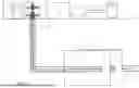
FIG. 1 is a diagrammatic overview of the invention.
FIG. 2 depicts temperature vs time for enhanced recovery techniques as described herein.
FIG. 3 (prior art) depicts a representation of propagated fractures in a wellbore.
FIG. 4 is a flowchart illustrating a method for treating shale formations using cyclic steam injection.
DETAILED DESCRIPTION OF THE PREFERRED EMBODIMENT
The present invention is directed to a method of increasing oil and gas production from subterranean formations. The method has particular utility with hydraulically-fractured shales, and may be employed in oil wells, gas wells, and/or gas condensate wells. The invention includes all the advantages of prior art gas-injection projects, but adds numerous other effective recovery mechanisms. Introducing hot gases (heated water vapor with or without added solvent gases such as CO2, N2, and methane) will include all the advantageous recovery mechanisms of the current hot gas injection method.
The present invention is an improvement on what currently exists. The present invention is an improvement in at least the following ways: it introduces heating, it is a cyclic process, it uses gases that are more effective at recovering oil, and it is designed to heat the fracture rather than injecting gases directly into the reservoir.
The invention works through exposing the entire well and fracture system to heated water vapor and other gases in a way that cycles between low and high pressures. This causes an increased and longer-lived driving force for flow from reservoir to well, it increases amount of oil removed by the gas, it increases fluid mobility for greater flow to the well, and increases penetration depth of the process into the reservoir.
The invention includes all the advantages of prior art gas-injection projects but adds numerous other effective recovery mechanisms including thermal conduction, enhanced oil vaporization of via steam distillation, reduced oil viscosity, thermal expansion, thermal desorption of trapped gas, and improved well productivity. Introducing hot gases (heated water vapor with or without added non-aqueous gases such as CO2, N2, and methane) will include all the advantageous recovery mechanisms of the current hot gas injection method.
Thermal Conduction-Steam does not have to enter the rock to achieve heating of rock and its resident oil and gas via thermal conduction—it only has to fill the fracture space. This is feasible for contacting a large amount of oil in a short amount of time due to the enormous surface area of rockface exposed by hydraulic fractures and their connecting natural fracture networks. Since this does not require steam to enter the rock, steam can be injected at much lower pressures, where steam is a more effective heat-transfer medium due to its increased latent heat at lower pressures. Moreover, injecting at lower pressures is not possible in conventional reservoirs, especially in deeper wells such as most shale wells, because the reservoir fluids would quickly flow into the fractures and force the attempted low-pressure injectant to be produced. However, in unconventional reservoirs the reservoir permeability is so low that fluids take so long to flow into the fractures that fluids can be readily injected into the well at pressures much lower than the prevailing reservoir pressure. Furthermore, the production cycle of this process occurs at even lower pressures, enabling steam to be an even more effective heat carrier.
Vaporization by Steam Distillation-Steam exposes the in situ oil to vapor space. Exposing a liquid to vapor always promotes vaporization, but in the case of exposure of oil to steam there are three (3) factors that further enhance vaporization: 1) Heating rock up from initial temperature to steam temperature drives some of its resident liquid water into the vapor. This increase in the amount of vapor increases the in situ vapor's capacity to vaporize oil. 2) The primary mechanism of steam distillation is driven by the fact that a vapor composed of water has a greater capacity for vaporizing oil than does a hydrocarbon vapor at the same conditions. Increased presence of water in a vapor reduces the hydrocarbon partial-pressure in the vapor, and the lower the vapor's hydrocarbon partial-pressure, the greater its capacity for vaporizing additional oil. 3) Unlike exposure of the in situ oil to a cold gas injectant, steam increases the temperature, and vaporization occurs to a much greater degree at higher temperature than it does at lower temperature.
Reduced Oil Viscosity—Some of the initial oil that exits the rock into the fractures does so in the form of hot vapor, but some also leaves the rock in the form of liquid oil. The rate at which this happens is directly proportional to the oil's viscosity, and oil viscosity is a strong function of temperature. Thus, hot oil is less viscous, and exits the rock at a higher rate, which results in increased oil production for the well.
Thermal Expansion—The fluids in the reservoir rock fill the void volume available in the rock. Therefore, if the fluid's volume can be increased by some means, their volume becomes too much for the rock to hold and they will flow into the fractures to be produced from the well. Advantageously, this is precisely what happens when oil is heated-its volume expands, and by that mechanism some of it is driven to exit the rock and be produced. Furthermore, the rock grains adjacent to the fluids become heated as well, and they swell and expand in volume also. This reduces the amount of void volume available to hold the fluids, and further drives even more oil to the fractures to be produced.
Thermal Desorption—It is well known in unconventional reservoirs that, owing to its small-sized pores, there are large amounts of light hydrocarbon components (mostly methane) that are adsorbed against the rock grain surfaces inside the pores of the rock. It is also well known that only a small fraction of these adsorbed components can be desorbed by decreasing pressure to the levels realized during production of the wells. It is well known also that these adsorbed components would be readily released via thermal desorption if the rock could somehow be heated. By introducing hot steam, steam desorption is enabled as a recovery mechanism, and these fluids that are otherwise left behind can be readily produced.
Improved Well Productivity—In some wells, hydraulic fractures were generated using a fluid containing polymers. While potentially advantageous for making fractures, the polymers can create a gel that is left behind, which in turn can create very viscous blockages in the fractures that impair flow of fluids from the reservoir rock to the wellbore, leading to reduced production. However, at elevated temperatures (such as that of steam), these blocking gels decompose into new compounds that have low viscosity and can readily flow, and which no longer block flow, leading to improved performance in terms of wells productivity. Furthermore, for all wells, the presence of a greater amount of liquid in its vertical section leads to lower production rates, due to the weight of this dense liquid pushing down on the otherwise non-dense fluid column. The increased temperature that results from steam causes more of the well stream to be in the vapor phase rather than liquid and this increases production rates in the well.
The present inventive methods expose the entire well and fracture system to heated water vapor, or steam, and other gases in a way that cycles between low and high pressures. During the high pressure cycles steam fills the wellbore, the man made propped fractures, and the connected system of unpropped natural fractures, and immediately begins to conduct heat into the adjacent rock and its resident oil and gas via thermal conduction. This heating enables multiple recovery mechanisms, including thermal expansion, reduced oil viscosity, enhanced vaporization from steam distillation, and thermal desorption. During the low-pressure cycles: fluids flow energetically towards the surface, owing to the expansion of the hot fluids caused by the reduction in pressure. Also steam continues to heat the formation. The high and low pressure cycles cause an increased and longer-lived driving force for flow from reservoir to well, an increased amount of oil removed by the gas, an increase in the fluid mobility for greater flow to the well, and an increase in the penetration depth of the process into the reservoir.
Benefit of increased driving force. Given the amount of oil in place, it is produced at higher production rates when the driving force for flow is higher.
Benefit of increased oil removed by gas. This causes more oil to be produced by the process for a given amount of gas injected. This means a greater oil production rate for the well.
Benefit of increase in fluid mobility for greater flow to the well. For a given amount of driving force, higher fluid mobility means fluid will flow at a greater flow rate. This means a greater production rate for the well.
Benefit of increased penetration depth. The greater depth of penetration that a process can achieve, the more reservoir rock that is exposed to enhanced recovery mechanisms. This results in more oil exiting the rock, which means more oil production for the well.
The present invention includes a method of increasing production of hydrocarbons comprising gas from a wellbore formed in subterranean rock formations. Accordingly, the method comprises: generating steam and injecting said steam into a wellbore, sealing said well to trap said steam, maintaining the seal for a predetermined amount of time to affect conductive heating of said rock formations, and releasing said seal to allow the flow of hydrocarbons. Further it is contemplated that heat loss occurring from injecting said steam to said wellbore is reduced by lining said well with thermal insulation. Further, it is contemplated that steam is injected into the wellbore at a flow rate that is preferable to reduce heat loss.
In some embodiments, said steam is injected via one or more conduits, each of said conduits having an inner and outer annulus, said outer annulus containing a gas for insulation.
In some embodiments, a thermal packer is positioned to reduce steam loss. In the preferred embodiment, the tubing extends from the surface wellhead down only to the end of the vertical section, and the packer is located near the bottom of the tubing. In one embodiment, a normal thermal packer arrangement is installed, which seals between the casing and tubing but also allows for thermal expansion of the tubing. In another embodiment, a “leaky” packer arrangement is installed, wherein the seal between the bottomhole and the annulus is not complete which allows some flow, wherein some gas is injected into the casing at the surface. This gas flow helps keep the annulus cool on its way down the casing while also providing a form of gas lift as it travels back up the tubing along with produced fluids, improving both tubing insulation and well performance (via the added artificial lift of the gas).
In some embodiments, N2 foam may be injected before said steam injection to increase said hydrocarbon production. It is well known that the horizontal section of the wellbore can become clogged with extant fluids and other residues and/or materials after drilling and oil extraction is done. Accordingly, injecting N2 foam prior to steam injection is an effective way to clean out any remaining extant fluids, residues and/or other materials existing in the well from previous drilling and extraction that may exist on shale face and decrease the ability for hydrocarbons to exit the shale. By cleaning out unwanted extant fluids, residues, and materials, the permeability of the shale in the formation is increased, or at least returned to its original permeability prior to drilling and extraction.
In some embodiments, the well may be swabbed before said steam injection to increase said hydrocarbon production. It is well known the horizontal section of the wellbore can become clogged with extant fluids and other residues and/or materials after drilling and oil extraction is done. Accordingly, swabbing the well prior to steam injection is an effective way to clean out any remaining residues and/or other materials existing in the well from previous drilling and extraction. Swabbing the well, to reduce the pressure of fluids in the fracture network, and/or remove extant liquids from the fracture network is a well known technique which may be used in conjunction with the inventive method. By cleaning out remaining residues, the permeability of the shale is increased, or at least returned to its original permeability prior to drilling and extraction.
In some embodiments, other gasses may be injected along with said steam. Accordingly, other gasses that may be injected along with said steam may include, but are not limited to: CO2, N2, air, hydrocarbon gasses, flue gasses, and other known suitable gasses, and/or any combination thereof. It is contemplated that injecting other gasses may be useful at least for moderating steam temperature, and increasing gas volume fraction and gas flow rate of the wet steam.
In some embodiments, said steam may be injected at a low pressure. For example, a low pressure steam injected may be approximately 500 psi.
Further, it is contemplated that said steam may be injected cyclically, alternating between high pressure, via steam injection, and low pressure, via production of steam and reservoir fluids. During the “high pressure” part of the cycle high pressure steam is injected, while during the “low pressure” part of the cycle, the well is opened up to production of the pressurized steam and reservoir fluids. For example, high pressure steam may be injected at high pressure of approximately 1500 psi for 7 days, the well is shut for 7 days to allow the steam to soak into the shale for 7 days, and then production of the well is commenced, reducing the internal pressure to a low pressure for 7 days.
In some embodiments, an aerial cooler is positioned to prepare hot produced fluids for existing surface production equipment.
Further, it is contemplated that said method may be employed in a shale in an oil window. Even further, it is contemplated that said method may be employed in a shale in a gas window. Even further still, it is contemplated that said method may be employed in oil wells, gas wells, or gas condensate wells.
In some embodiments that additives are injected along with the steam, said additives comprising at least one of salts, surfactants, chemically reactive agents, pH-altering agents, nanoparticles, gasses, and solvents. There are a number of purposes and benefits related to injecting other additives along with the steam. For example, salt may added to keep certain salinity in the mixture of native salty water and fresh water condensing from steam injected to prevent clay swelling in the formation. Further, it is well known that solvents can improve oil recovery. Further, surfactants and/or nanoparticles can result in foams that allow hot steam vapor to better access the lower portions of the fractures.
In some embodiments, agents are injected intermittently with steam injection, said agents comprising at least one of surfactants, chemically reactive agents, pH-altering agents, nanoparticles, gasses, and solvents.
Further, it is contemplated that the steam may generated downhole in said wellbore, where said steam may be generated by either downhole steam generators, electromagnetic heating, downhole electrical heater cables, or exothermically reactive injectants.
In some embodiments, said steam is cyclically injected into two or more neighboring wells having connected fracture networks. Accordingly, it may be the case that two individual wells installed in individual locations may be connected by way of connected fracture networks. Fracture networks oftentimes exist as well-connected subterranean systems comprising a plurality of sub-system networks, the sub-system networks connected to each other. Steam may be injected into a Well A and into a Well B, wherein both Well A and Well B lead to the same interconnected subterranean fracture network. In some embodiments, steam is cyclically injected into the two or more neighboring wells by way alternating between injecting high-pressure steam into a first well, and injecting high-pressure steam into a second well. Alternatively, steam may be injected into Well A while being produced from Well B.
FIG. 1 shows the apparatus for the invention. Fuel (A) powers a steam generator (B), said steam generator (B) heats up feed water (C) until most of the feed water (C) becomes a hot high-pressure vapor. During the high-pressure flow-in stage of the process described above, steam flows in through the wellhead (D), down through the centralized tubings (I), which are placed using a thermal packer (J) inside the casings (M) located in the well's vertical (E) and horizontal (F) sections, and fills the fractures (G). It is understood that said process may also be used for wells where the horizontal section is uncased, although uncommon for shale wells. During the soak period, the wellhead (D) is closed, and the well is shut-in, while the reservoir takes in the steam's heat. During the low-pressure flow-out period, the wellhead (D) is open to the aerial cooler (H) and production system (K) to accept flow of downhole fluids. Vacuum Insulated Tubings or centralized tubings (I) sit inside the well casing with the annulus space (L) filled with natural gas, nitrogen, air, CO2 or any type of inert gas to provide required thermal insulation. The steam injection or flow-in stage is preferably done at the maximum flow rate possible with the equipment used, which rate would be apparent to one of skill in the art. The max flow technique protects existing casing (M) from excess (prolonged) heating, and to keep produced fluids hot so that they flow as vapor and increase well deliverability (i.e., hydrocarbon production). The tubings may be slotted to release excess heat and minimize the possibility of collapse from overheating. Slotting would be done in horizontal sections of the tubing. Alternatively, low pressure low flow rate steam may be injected into the well. The techniques of swabbing and N2 foam injection may also be used to increase production. Swabbing the well, to reduce the pressure of fluids in the fracture network, and/or remove extant liquids from the fracture network is a well known technique which may be used in conjunction with the inventive method. Injecting other gases along with the steam may also increase production. An aerial cooler near the wellhead prepares the hot produced fluids for existing surface production equipment in the field. A thermal packer may also be used.
FIG. 2 depicts temperature vs time for enhanced recovery techniques as described herein. It should be noted that as soon as one day of steam exposure, rock up to 1 ft away from the fracture face has been heated substantially higher than its initial reservoir temperature, which in this example is 80° C.
FIG. 3 depicts a representation of propagated fractures in a wellbore, where F represents the horizontal wellbore, P represents a single fracture lobe held open by proppant, and R represents the network of unpropped natural fractures that emanate out from the man-made fracture. Steam injected into wellbore F will flow to fill the void space in fracture P and the proceed to fill the network of natural fractures R. Note that there are dozens of fractures like P created in a single horizontal wellbore F.
In accordance with the inventive method, there are a number of steps to provide for extracting an increased amount of hydrocarbons from the wellbore.
FIG. 4 is a flowchart illustrating an exemplary method to provide increased extraction of hydrocarbons from a wellbore. In general, the method may be accomplished by performing the following steps: (i) setting up a steam generator near a wellhead of a well configured to extract hydrocarbons from a rock formation, (ii) installing a liner in the well, (iii) flowing into the wellhead a mixture of heated water vapor, hot water, and/or solvent gasses, (iv) filling the wellhead and the wellbore and fracture network, (v) sealing the wellhead, (vi) allowing the mixture to soak into the rock formation, (vii) opening the wellhead to allow for hydrocarbon extraction, (viii) repeating steps (i)-(vii) until a desired amount of hydrocarbons are extracted from the rock formation.
With reference to FIG. 4, first, at step 702, a steam generator is set up at surface level adjacent near a wellhead of a horizontal well that penetrates a shale rock formation and has been hydraulically fractured through the shale.
Next, at step 704, liner is installed in the well using known techniques. Accordingly, heat loss from injecting said steam to wellbore is reduced by installing a thermal insulation along a length of a vertical section of the wellbore.
Next, at step 706, a flow-in cycle begins, where the steam generator flows in a mixture of heated water vapor and hot water with or without solvent gases (including CO2, N2, and/or other gases) through the wellhead to fill the well and the fracture network with steam. The rate, temperature, and duration requires some trial and error to achieve a desired rate of production for each individual well as would be apparent to one of skill in the art. Steam may be injected at a plurality of spaced locations along the horizontal well. It is potentially beneficial to pack-off the horizontal well a section at a time, and administer steam treatment starting at the toe and moving later to the heel. Some other variables include administering steam at different temperatures and pressures, and at different steam qualities, as well as co-injecting other gases such as CO2, N2, air, hydrocarbon gases, flue gases, etc., along with the hot water vapor.
Next, at step 708, the wellhead is sealed, allowing for the soak period to begin. During this step, steam from the steam generator is hydraulically isolated from the well and the well is sealed off using conventional means.
Next, at step 710, the soak period begins. The trapped and heated steam is allowed to soak for a period, the duration of which will vary depending upon how much oil production is desired. This heating process sets up a temperature profile of hot rock and fluids out into the reservoir to an increasing penetration depth with time. In other words, the oil shales are conductively heated for an extended period of time. The amount of time for this step is also variable and would be optimized for a given production goal using trial-and-error techniques as would be apparent to one of skill in the art. In one embodiment, the method includes 7 days of injection, 7 days of soaking, and then 7 days of production. In another embodiment, the method includes 1-10 days of injection, 1-7 days of soaking, and then 1-3 months of production. However, the duration of the soak period may be as small as zero minutes.
Next, at step 712, the well is opened, allowing the well to produce oil & gas, and causing the pressure of fluid in the fractures to drop. Oil and gas from the reservoir will flow into the well and to the surface during this period.
Finally, at step 714, steps 702-712 are repeated cyclically to maximize production, until a desired amount of hydrocarbon extraction is achieved.
It should be noted that in accordance with an aspect of the invention, the inventive method may be used in neighboring wells simultaneously. That is, steam may be cyclically injected in two or more neighboring wells whose fracture networks are connected, as is known to happen occasionally in the industry. For example, while Well A is undergoing its soak or production period, neighboring Well B could be undergoing its injection period. In this manner, the steam generator stays active and is used to maximum affect instead of sitting idle. Alternatively, steam may be injected into Well A while being produced from Well B, followed by a period of injecting into Well B and producing from Well A.
It is to be understood that the present invention is not limited to the sole embodiment described above, but encompasses any and all embodiments within the scope of the following claims:
Claims
1. A method of increasing production of hydrocarbons from a wellbore formed in subterranean rock formations, the method comprising:
generating steam and injecting said steam into the wellbore;
sealing said wellbore to trap said steam, and maintaining a seal for a period of time to affect conductive heating of said rock formations;
releasing said seal to allow a flow of hydrocarbons; and
repeating the method until a desired amount of hydrocarbons is extracted.
2. The method of claim 1 wherein heat loss from injecting said steam to wellbore is reduced by installing a thermal insulation along a length of a vertical section of the wellbore.
3. The method of claim 1 wherein steam is injected into the wellbore at a flow rate to reduce heat loss.
4. The method of claim 1 wherein said steam is injected via one or more conduits, wherein multiple such conduits form an inner and outer annulus, said outer annulus containing a gas for insulation.
5. The method of claim 4 wherein a thermal packer is positioned to reduce steam loss.
6. The method of claim 1 wherein N2 foam is injected before said steam injection to increase said hydrocarbon production.
7. The method of claim 1 wherein the well is swabbed before said steam injection to increase said hydrocarbon production.
8. The method of claim 1 wherein other gases are injected along with said steam.
9. The method of claim 1 wherein an aerial cooler is positioned to prepare hot produced fluids for existing surface production equipment.
10. The method of claim 1 wherein said method is employed in a shale in an oil window.
11. The method of claim 1 wherein said method is employed in a shale in a gas window.
12. The method of claim 1 wherein said method is employed in oil wells, gas wells, or gas condensate wells.
13. The method of claim 1 wherein additives are injected along with the steam, said additives comprising at least one of salts, surfactants, chemically reactive agents, pH-altering agents, nanoparticles, gases, and solvents.
14. The method of claim 1 wherein agents are injected intermittently with steam injection, said agents comprising at least one of surfactants, chemically reactive agents, pH-altering agents, nanoparticles, gases, and solvents.
15. The method of claim 1 wherein steam is generated downhole in said wellbore, where said steam may be generated by either downhole steam generators, electromagnetic heating, downhole electrical heater cables, or exothermically reactive injectants.
16. The method of claim 1 wherein steam is cyclically injected in two or more neighboring wells having connected fracture networks.
17. The method of claim 1 wherein steam is injected in one well while steam and hydrocarbons are being produced in a neighboring well having a connected fracture network, followed by a period of switching which well is being injected with steam and which well is producing steam and hydrocarbons.
Images & Drawings included:


Sources:
- United States Patent and Trademark Office - verify current appl. status at the USPTO↗
Recent applications in this class:
- » 20250145890 2025-05-08
SOLVENT EXTRACTION METHOD FOR PETROLEUM SLUDGE/OIL SAND ASSISTED BY PARTICLE DISPERSANT - » 20240376384 2024-11-14
High Shear Method to Separate Fractions in Woody Biomass - » 20230235232 2023-07-27
MULTISTAGE OIL RECLAMATION SYSTEM - » 20230159832 2023-05-25
VERTICAL CONTINUOUS MULTIPHASE REACTOR FOR THE CLEAN PRODUCTION OF HYDROCARBONS AND ENERGY AND THERMOCHEMICAL METHOD CARRIED OUT - » 20230043762 2023-02-09
Solvothermal liquefaction process from biomass for biocrude production - » 20230041631 2023-02-09
METHOD AND SYSTEM FOR FLOTATION SEPARATION IN A MAGNETICALLY CONTROLLABLE AND STEERABLE MEDIUM - » 20210054290 2021-02-25
Renewable energy use in oil shale retorting - » 20200385638 2020-12-10
RADIAL FLOW OIL SHALE RETORT - » 20200056098 2020-02-20
System for production of a renewable liquid fuel - » 20200048560 2020-02-13
Enhanced temperature control of bitumen froth treatment process