DOWNHOLE TOOLS AND SYSTEMS AND RELATED METHODS OF USE
US20260028892A1
2026-01-29
19/280,684
2025-07-25
Smart Summary: A downhole tool is designed to be used inside a wellbore, which is a deep hole drilled into the ground. It has a central part called a mandrel, surrounded by other components that help it function. There is a cone-shaped piece and a key that fits into a special pocket on the tool. This design includes a feature that prevents the tool from rotating while in use. Overall, the tool is built to perform specific tasks safely and effectively in challenging underground environments. 🚀 TL;DR
Abstract:
A downhole tool or assembly suitable for use in a wellbore, the tool having a mandrel with an outer surface. The downhole tool includes one or more components disposed around the mandrel. A cone or comparable piece at least one key disposed in a preformed pocket. The downhole tool includes an anti-rotation feature or mechanism.
Inventors:
- Derek Slater Payne 9 🇺🇸 Katy, TX, United States
- Santiago Galvez Porta 1 🇬🇧 Aberdeen, United Kingdom
- Grant Matthew Tollette 1 🇺🇸 Houston, TX, United States
- Andrew James Cayson 1 🇺🇸 Houston, TX, United States
Applicant:
Interested in similar patents?
Get notified when new applications in this technology area are published.
Classification:
E21B33/129 » CPC main
Sealing or packing boreholes or wells in the borehole; Packers; Plugs with mechanical slips for hooking into the casing
Description
STATEMENT REGARDING FEDERALLY SPONSORED RESEARCH OR DEVELOPMENT
Not applicable.
BACKGROUND
Field of the Disclosure
This disclosure generally relates to downhole tools and related systems and methods used in oil and gas wellbores. More specifically, the disclosure relates to a downhole system and tool that may be run into a wellbore and useable for wellbore isolation, and methods pertaining to the same. In particular embodiments, the downhole tool may be a plug suitable to provide a reliable gas-tight seal.
Background of the Disclosure
An oil or gas well includes a wellbore extending into a subterranean formation at some depth below a surface (e.g., Earth's surface), and is usually lined with a tubular, such as casing, to add strength to the well. Many commercially viable hydrocarbon sources are found in “tight” reservoirs, which means the target hydrocarbon product may not be easily extracted. The surrounding formation (e.g., shale) to these reservoirs typically has low permeability, and it is uneconomical to produce the hydrocarbons (i.e., gas, oil, etc.) in commercial quantities from this formation without the use of drilling accompanied with fracing operations.
A frac plug and accompanying operation may be such as described or otherwise disclosed in U.S. Pat. No. 8,955,605, incorporated by reference herein in its entirety for all purposes. FIG. 1 illustrates a conventional plugging system 100 that includes use of a downhole tool 102 used for plugging a section of the wellbore 106 drilled into formation 110. The tool or plug 102 may be lowered into the wellbore 106 by way of workstring 112 (e.g., e-line, wireline, coiled tubing, etc.) and/or with setting tool 117, as applicable. The tool 102 generally includes a body 103 with a compressible seal member 122 to seal the tool 102 against an inner surface 107 of a surrounding tubular, such as casing 108. The tool 102 may include the seal member 122 disposed between one or more slips 109, 111 that are used to help retain the tool 102 in place.
In operation, forces (usually axial relative to the wellbore 106) are applied to the slip(s) 109, 111 and the body 103. As the setting sequence progresses, slip 109 moves in relation to the body 103 and slip 111, the seal member 122 is actuated, and the slips 109, 111 are driven against corresponding conical surfaces 104. This movement axially compresses and/or radially expands the compressible member 122, and the slips 109, 111, which results in these components being urged outward from the tool 102 to contact the inner wall 107.
In this manner, the tool 102 provides a seal expected to prevent transfer of fluids from one section 113 of the wellbore across or through the tool 102 to another section 115 (or vice versa, etc.), or to the surface. Tool 102 may also include an interior passage (not shown) that allows fluid communication between section 113 and section 115 when desired by the user. Oftentimes multiple sections are isolated by way of one or more additional plugs (e.g., 102A).
The setting tool 117 is incorporated into the workstring 112 along with the downhole tool 102. Examples of commercial setting tools include the Baker #10 and #20, and the ‘Owens Go’. Upon proper setting, the plug may be subjected to high or extreme pressure and temperature conditions, which means the plug must be capable of withstanding these conditions without destruction of the plug or the seal formed by the seal element.
The wellbore may be the subject of other downhole tools (including those that provide a seal), such as a packer or a bridge plug, depending on the service or operational need. There are times through the life of the wellbore that production may no longer be needed or possible, and the wellbore wished closed off or shut in.
A tool known for this is termed a permanent (bridge) plug due to the long-term nature of its use. A composite-type plug is not a viable choice for a permanent solution; the material degrades fairly quickly in downhole environments, and is also not usable in higher temperature environments. As such, permanent plugs tend to be made of rugged, durable metals.
Most jurisdictions have high standards or requirements in place related to a shut-in well, due to the critical need to ensure no leakage. API 11D1 (comparable to ISO 14310) is a known standard intended to establish guidelines for both manufacturers and end users in the selection, manufacture, design, and laboratory testing of many types of plugs, including permanent bridge plugs.
There are three grades, or levels, established for quality control and six grades (plus one special grade) for design verification. Validation grades vary from Q3 to Q1, with grade Q3 representing the minimum requirements and Q1 representing the highest level of verification. Similarly, the are six standard design-validation grades range from V6 to V1. V6 is the lowest grade, and V1 represents the highest level of testing. A special V0 (V-zero) grade represents special acceptance criteria requirements for the market conditions of today (including increased awareness and scrutiny on environmental concern), namely, ‘zero bubbles’ (no gas leakage).
However, permanent plugs struggle to reliably and predictably provide results suitable to reach V0 standards. First, during downhole setting, forces are not always applied equally, and setting is uneven (leaving the plug at greater risk of failure or leakage, and sometimes requiring immediate removal so that a better seal may be achieved).
These plugs are also susceptible to losing seal due to fluctuations (including sometimes extreme) in temperature and pressure, which impacts expansion and contraction properties of the plug components. The cycle of temperature may be real-world or testing. The physical change of components results in loss of seal. Plugs can sometimes handle a partial cycle, such as going from high temperature to lower temperature. But upon return to high temperature, leak or fail.
Then, even in the instance where use is considered permanent, there may always come a time when the plug needs to be removed (such as when (re) production of the well is chosen or when the wellhead requires workover). The drillout of such a plug is problematic because the durable metal is not easily drilled, and moreover, some parts are engaged together in a way that results in slippage and constant rotation of the bit. Such drillout routinely encounters one or more time consuming and expensive interventions.
Accordingly, there are needs in the art for a downhole tool able to provide reliable barrier integrity and drillability in high temperature cycle gas in satisfaction of strict requirements, such as V0. There is a need to provide a plug with components that may ‘catch’ instead of freely rotate during drilling, as well as to promote even and symmetrical slip fracture. Other needs include case of manufacture to achieve desired component geometry and at the same time anti-slippage or anti-rotation, including for drill-thru capabilities.
SUMMARY
Embodiments of the disclosure pertain to a downhole tool (and related systems and methods) for use in a wellbore. Such tools may include a mandrel having a distal end; a proximate end; and an outer surface.
A downhole tool of any embodiment that may include an anti-rotation or anti-slippage configuration.
A downhole tool of any embodiment that may include a mechanical coupling between a slip and another component, such as when the downhole tool is in a set configuration.
Embodiments of the disclosure my include a downhole tool for use in a wellbore. The downhole tool may have one or more of: a mandrel comprising: a distal end, a proximate end, and an outer mandrel surface; at least one component disposed on the mandrel in a run-in configuration, and between the distal end and the proximate end; and/or an anti-rotation mechanism engaged with a first end of the at least one component.
The mechanism may include an at least one movable member movingly engaged with the outer mandrel surface. The downhole tool may be selectably engageable to a surrounding surface in the wellbore. The downhole tool may include a first slip and a second slip, each disposed around the mandrel in the run-in configuration. The downhole tool may be configured to move from a run-in configuration to an at least one of: a set configuration, a disconnected configuration, and combinations thereof.
An anti-rotation mechanism of any embodiment may facilitate (linear) longitudinal movement between an at least one component and the mandrel when the downhole tool is moved from the run-in configuration to a set configuration. The anti-rotation mechanism may include a lock or comparable type feature configured to prevent rotational movement between the at least one component and the mandrel.
A component, such as a cone or cone member, may include an end or surface configured with a key. The key could be integral or separately coupled therewith. As an example, the key may have a key nose portion and a key back end. The key nose portion may include a first width. The key back end may have a second width. In aspects, the second width may be greater than the first width. The key nose portion comprises a tapered top surface.
An at least one component of embodiments may be a sleeve configured with a first sleeve end and a second sleeve end. The first sleeve end may have a key receptacle with a key disposed therein. The second sleeve end may include a pocket with the at least one movable member at least partially disposed therein.
Other embodiments herein may provide for a downhole tool for use in a wellbore, the downhole tool comprising: a mandrel comprising: a distal end, a proximate end, and an outer mandrel surface. There may be a cone or cone-type member disposed around the mandrel. The cone may have a first cone end configured with a plurality of cone key receptacles, and a second cone end.
The downhole tool may have a sleeve or housing type structure disposed around the mandrel. The sleeve may include: a first sleeve end configured with a plurality of sleeve key receptacles, and a second sleeve end configured with a plurality of pockets.
The downhole tool may utilize a backup or expansion ring disposed around the mandrel. The backup ring may have a ring end configured with a plurality of ring slots, each one of the plurality of ring slots respectively positioned proximately to each one of the plurality of pockets.
There may be one or more movable members. Any or each one of the plurality of movable members may be respectfully disposed at least partially within each of one of the plurality of ring slots and each one of the plurality of pockets.
Any embodiment herein may have the downhole tool with a first slip disposed around the mandrel. The first slip may include a first longitudinal slip groove positioned proximate to the key nose portion. The movable members may be movably engaged with the outer surface to facilitate longitudinal movement therebetween.
Any downhole tool of the disclosure may have the mandrel with one or more components disposed therearound. An at least one component thereof may include a device, such as a key or dog, which may be configured to engage a slip. In aspects, the engagement may promote substantially even fracture of the slip.
Any downhole tool of the disclosure may include a bean spring or spring sleeve. Such a device may be used to help maintain a reliable seal of the downhole tool against a surrounding surface under conditions where wellbore temperature is changing over time.
Embodiments herein may provide for a downhole tool in the form of a bridge plug rated in satisfaction of V0 requirements. The bridge plug may be a permanent bridge plug rated to shut-in a wellbore.
In aspects, any downhole tool of the disclosure may have one or more components thereof made of a durable metal, such as cast iron. In other aspects, any downhole tool of the disclosure may be drillable. For example, a permanent bridge plug of the disclosure may be drillable. In drillout, the downhole tool may utilize an anti-rotation or anti-slippage configuration.
These and other embodiments, features and advantages will be apparent in the following detailed description and drawings.
BRIEF DESCRIPTION OF THE DRAWINGS
A full understanding of embodiments disclosed herein is obtained from the detailed description of the disclosure presented herein below, and the accompanying drawings, which are given by way of illustration only and are not intended to be limitative of the present embodiments, and wherein:
FIG. 1 is a side view of a process diagram of a conventional plugging system;
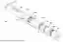
FIG. 2A shows an isometric view of a system having a downhole tool, according to embodiments of the disclosure;
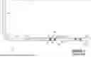
FIG. 2B shows an isometric, partial component breakout view of a downhole tool, according to embodiments of the disclosure;
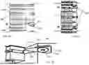
FIG. 3A shows a longitudinal side cross-sectional view of a downhole tool in a run-in configuration according to embodiments of the disclosure;
FIG. 3B shows a longitudinal side cross-sectional view of the downhole tool of FIG. 3A moved to a set configuration according to embodiments of the disclosure;
FIG. 3C shows a longitudinal side cross-sectional view of the downhole tool of FIG. 3A moved to a disconnected configuration according to embodiments of the disclosure;
FIG. 3D shows a close-up side view of a component of a downhole tool having a key proximate a slip according to embodiments of the disclosure;
FIG. 3E shows a close-up view of the key of FIG. 3D in a pocket or receptacle of the component according to embodiments of the disclosure;
FIG. 3F shows a close-up side view of the key of FIG. 3D engaging the slip according to embodiments of the disclosure;
FIG. 3G shows a close-up view of a component having a pocket or receptacle for a key according to embodiments of the disclosure;
FIG. 3H shows a lateral cross-sectional view of an anti-slippage or rotation feature for a downhole tool according to embodiments of the disclosure;
FIG. 3I shows a close-up lateral cross-sectional view of part of the anti-slippage feature of FIG. 3H according to embodiments of the disclosure;
FIG. 3J shows a lateral cross-sectional view of an anti-slippage feature for a downhole tool in a set configuration according to embodiments of the disclosure;
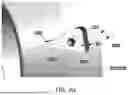
FIG. 4A shows a top end view of a key according to embodiments of the disclosure;
FIG. 4B shows an upward view of a bottom side the key of FIG. 4A according to embodiments of the disclosure;
FIG. 4C shows a bottom end view of the key of FIG. 4A according to embodiments of the disclosure;
FIG. 4D shows a downward view of a top side of the key of FIG. 4A according to embodiments of the disclosure;
FIG. 4E shows a longitudinal side view of a first side of the key of FIG. 4A according to embodiments of the disclosure;
FIG. 4F shows a longitudinal side view of a second side of the key of FIG. 4A according to embodiments of the disclosure; and
FIG. 4G shows an isometric view of the key of FIG. 4A according to embodiments of the disclosure.
DETAILED DESCRIPTION
Herein disclosed are novel apparatuses, systems, and methods that pertain to and are usable for wellbore operations, details of which are described herein.
Embodiments of the present disclosure are described in detail in a non-limiting manner with reference to the accompanying Figures. In the following discussion and in the claims, the terms “including” and “comprising” are used in an open-ended fashion, such as to mean, for example, “including, but not limited to . . . ”. While the disclosure may be described with reference to relevant apparatuses, systems, and methods, it should be understood that the disclosure is not limited to the specific embodiments shown or described. Rather, one skilled in the art will appreciate that a variety of configurations may be implemented in accordance with embodiments herein.
Although not necessary, like elements in the various figures may be denoted by like reference numerals for consistency and ease of understanding. Numerous specific details are set forth in order to provide a more thorough understanding of the disclosure; however, it will be apparent to one of ordinary skill in the art that the embodiments disclosed herein may be practiced without these specific details. In other instances, well-known features have not been described in detail to avoid unnecessarily complicating the description. Directional terms, such as “above,” “below,” “upper,” “lower,” “front,” “back,” “right”, “left”, “down”, etc., are used for convenience and to refer to general direction and/or orientation, and are only intended for illustrative purposes only, and not to limit the disclosure.
Connection(s), couplings, or other forms of contact between parts, components, and so forth may include conventional items, such as lubricant, additional sealing materials, such as a gasket between flanges, PTFE between threads, and the like. The make and manufacture of any particular component, subcomponent, etc., may be as would be apparent to one of skill in the art, such as molding, forming, press extrusion, machining, or additive manufacturing. Embodiments of the disclosure provide for one or more components that may be new, used, and/or retrofitted.
Various equipment may be in fluid communication directly or indirectly with other equipment. Fluid communication may occur via one or more transfer lines and respective connectors, couplings, valving, and so forth. Fluid movers, such as pumps, may be utilized as would be apparent to one of skill in the art.
Numerical ranges in this disclosure may be approximate, and thus may include values outside of the range unless otherwise indicated. Numerical ranges include all values from and including the expressed lower and the upper values, in increments of smaller units. As an example, if a compositional, physical or other property, such as, for example, molecular weight, viscosity, temperature, pressure, distance, melt index, etc., is from 100 to 1,000, it is intended that all individual values, such as 100, 101, 102, etc., and sub ranges, such as 100 to 144, 155 to 170, 197 to 200, etc., are expressly enumerated. It is intended that decimals or fractions thereof be included. For ranges containing values which are less than one or containing fractional numbers greater than one (e.g., 1.1, 1.5, etc.), smaller units may be considered to be 0.0001, 0.001, 0.01, 0.1, etc. as appropriate. These are only examples of what is specifically intended, and all possible combinations of numerical values between the lowest value and the highest value enumerated, are to be considered to be expressly stated in this disclosure. Others may be implied or inferred.
Embodiments herein may be described at the macro level, especially from an ornamental or visual appearance. Thus, a dimension, such as length, may be described as having a certain numerical unit, albeit with or without attribution of a particular significant figure. One of skill in the art would appreciate that the dimension of “2 centimeters” may not be exactly 2 centimeters, and that at the micro-level may deviate. Similarly, reference to a “uniform” dimension, such as thickness, need not refer to completely, exactly uniform. Thus, a uniform or equal thickness of “1 millimeter” may have discernable variation at the micro-level within a certain tolerance (e.g., 0.001 millimeter) related to imprecision in measuring and fabrication.
Terms
The term “connected” as used herein may refer to a connection between a respective component (or subcomponent) and another component (or another subcomponent), which can be fixed, movable, direct, indirect, and analogous to engaged, coupled, disposed, etc., and can be by screw, nut/bolt, weld, and so forth. Any use of any form of the terms “connect”, “engage”, “couple”, “attach”, “mount”, etc. or any other term describing an interaction between elements is not meant to limit the interaction to direct interaction between the elements and may also include indirect interaction between the elements described.
The term “fluid” as used herein may refer to a liquid, gas, slurry, multi-phase, etc. and is not limited to any particular type of fluid such as hydrocarbons.
The term “fluid connection”, “fluid communication,” “fluidly communicable,” and the like, as used herein may refer to two or more components, systems, etc. being coupled whereby fluid from one may flow or otherwise be transferrable to the other. The coupling may be direct or indirect. For example, valves, flow meters, pumps, mixing tanks, holding tanks, tubulars, separation systems, and the like may be disposed between two or more components that are in fluid communication.
The term “pipe”, “conduit”, “line”, “tubular”, or the like as used herein may refer to any fluid transmission means, and may be tubular in nature.
The term “composition” or “composition of matter” as used herein may refer to one or more ingredients, components, constituents, etc. that make up a material (or material of construction). Composition may refer to a flow stream, or the material of construction of a component of a downhole tool, of one or more chemical components.
The term “frac operation” as used herein may refer to fractionation of a downhole well that has already been drilled. ‘Frac operation’ can also be referred to and interchangeable with the terms fractionation, hydrofracturing, hydrofracking, fracking, fracing, frac, and the like. A frac operation can be land or water based.
The term “mounted” as used herein may refer to a connection between a respective component (or subcomponent) and another component (or another subcomponent), which can be fixed, movable, direct, indirect, and analogous to engaged, coupled, disposed, etc., and can be by screw, nut/bolt, weld, and so forth.
The term “machined” can refer to a computer numerical control (CNC) process whereby a robot or machinist runs computer-operated equipment to create machine parts, tools and the like.
Referring now to FIGS. 2A and 2B, an isometric view of a downhole system having a downhole tool for use in a wellbore, and an isometric, partial component breakout view of a downhole tool, respectfully, illustrative of embodiments disclosed herein, are shown. FIGS. 2A and 2B together depict a downhole system 200 may have a wellbore formed in a subterranean formation 210. The wellbore may be or include a tubular 208 disposed therein. In an embodiment, the tubular 208 may be casing (e.g., casing, hung casing, casing string, etc.) (which may be cemented), and the like, or in the event of an uncased well, could be the wellbore itself.
A workstring 212, the complete or upper end need not be shown (which may include a setting tool or device 217 coupled therewith [which may use a setting sleeve or other load bearing component]) may be used to position or run the downhole tool 202 into and through the tubular 208 to a desired location. One or more tool components may be disposed around a (tool) mandrel 214. Any component may be movingly (e.g., slidingly) or securely attached (such as via set screw), and in some instances a combination thereof, such as via shear member.
The downhole tool 202, as well as its components, may be annular in nature, and thus (centrally) disposed or arranged with respect to a longitudinal axis 258. The tool 202 may have a first or run-in configuration (position, etc.). The tool 202 may have a second or set configuration. The tool 202 may be movable from the first configuration to the second configuration. In the first or second configuration the tool 202 may remain, at least partially, engaged with the workstring 212. In a third or disconnect configuration, the tool 202 may be (completely) disengaged from the workstring 212.
In accordance with embodiments of the disclosure, the tool 202 may be configured as a plugging tool (such as a bridge plug), which may be set within the tubular 208 in such a manner that the tool 202 forms a fluid-tight seal against an inner surface 207 of the tubular 208. In aspects, the fluid-tight seal may be robust enough to prevent liquid or gas to pass thereby (such as up to the ppb level). The seal may be facilitated by a seal element 222 expanded into a sealing position against the inner surface 207.
The seal element 222 may be supported by or proximate to one or more backup rings or elements 223. The backup (or sometimes ‘expansion’) ring 223 may be disposed around the mandrel. Any backup ring 223 may be nested with one or more adjacent (backup) rings, which may provide additional expansion support. Once set, the downhole tool 202 may be held in place by use of an at least one slip 234a. The slip 234a may have a one-piece configuration. As shown here, there may be a first slip 234a and a second slip 234b (or also sometimes ‘bottom’ slip and ‘top’ slip, respectively).
In an embodiment, the downhole tool 202 may be configured as a bridge plug, whereby flow from one section of the wellbore to another (e.g., above and below the tool 202) is controlled. Other tool embodiments may be used, which may include whereby the downhole 202 may be configured where flow into one section of the wellbore may be blocked and otherwise diverted into the surrounding formation or reservoir 210.
Once the tool 202 reaches the set position within the tubular 208, the workstring 212 may be detached from the tool 202 by various methods, resulting in the tool 202 left in the surrounding tubular 208 and one or more sections of the wellbore isolated.
The setting force for the tool 202 may be determined by specifically designing the interacting surfaces of the tool 202 and the respective tool surface angles. The tool 202 may also be configured with a predetermined failure point (not shown) configured to fail, break, or otherwise induce fracture.
One or more components of tool 202 may be made of non-dissolvable materials (e.g., materials suitable for and are known to withstand downhole environments [including extreme pressure, temperature, fluid properties, etc.] for an extended period of time (predetermined or otherwise) as may be desired, such as carbon steel). The downhole tool 202 (and other tool embodiments disclosed herein) and/or one or more of its components may be 3D-printed or made with other forms of additive manufacturing.
The downhole tool 202 in an assembled, run-in configuration may have a general elongated shape with respect to a reference or axis 258. The downhole tool 202 may be run into the wellbore to a desired depth or position by way of the workstring 212 that may be configured with the setting tool assembly 217. The workstring 212 may be part of the tool system 200 utilized to run the downhole tool 202 into the wellbore and activate the tool 202 to move from an unset to set position.
The downhole tool 202 may include a lower sleeve 260, which may be disposed around and/or engaged with the mandrel 214. During setting, one of skill would appreciate there may be a push or pull resulting in urging components of the tool 202 into engagement. Once a first pre-determined force is exceeded, a shear member may shear, and components become movable.
The set configuration of the tool 202 (not shown here) may include the seal element 222 and/or (first or lower) slips 234a, 234b engaged with the tubular 208. The setting device(s) and components of the downhole tool 202 may be coupled with, and axially and/or longitudinally movable along or in a working relationship with the mandrel. When the setting sequence begins, the lower sleeve 260 may be pulled.
As the lower sleeve 260 is pulled or experiences force, the lower sleeve 260 (being engaged with the slip 234a) may urge the slip 234a to compressively slide against a cone (and its surface) 229. As it is desirous for the slip 234a to fracture, the slip 234a need not have any elongation of significance. As fracture occurs, the slip (or segments thereof) 234a may also move radially outward into engagement with the surrounding tubular 208.
To aid holding seal after periods of being exposed to dramatic temperature changes, the tool 202 may have a main housing or sleeve (such as a bean spring) 235. Although not limited, the sleeve 235 may be configured to expand and contract to some amount, which may be useful to keep the tool 202 completely sealed against the tubular 208.
The setting device(s) and components of the downhole tool 202 may be coupled with, and axially and/or longitudinally movable along mandrel 214. When the setting sequence begins, the mandrel may be pulled into tension while the setting sleeve remains stationary. The lower sleeve 260 may be pulled as well because of its attachment to the mandrel by virtue of the coupling of threads or other mating feature. As shown, the cone 229 and/or sleeve 235 may be configured with a key(s) (guide pin, dog, splitter, etc.) 238 (for receptacle(s) 237), which may be aligned with grooved features of the slips 234a, 234b to promote or facilitate even fracture (such as in grooved regions 244).
As the lower sleeve 260 is pulled, the components disposed about mandrel between the lower sleeve 260 and bearing sleeve 283 may begin to compress against one another. Because a setting sleeve may be held rigidly in place, the setting sleeve may engage against the bearing plate 283 that may result in the transfer load through the rest of the tool 202. The resultant movement causes compression and expansion of seal element 222. Additional tension or load may be applied to the tool 202 that results in complete setting, and eventually disconnect.
As the downhole tool 202 may be robust or durable, such as for instances intended as a more permanent or extended usage (over time), the downhole tool 202 may utilize an anti-slippage or -rotation mechanism. The mechanism may include the use of one or more movable members 281 disposed within the tool 202, such as at least partially within member slots or receptacles 282 (of ring 223). The movable members 281 may also be disposed at least partially within respective sleeve pockets or slots 286. The mechanism provides a point of (movable) mechanical coupling between the ring 223 and the sleeve 235. In the same context, a shear feature (such as a shear pin) 205 may be used to couple the sleeve 235 with the mandrel 214.
Referring now to FIGS. 3A, 3B, 3C, 3D, 3E, 3F, 3G, 3H, 3I, and 3J together, a longitudinal side view of a downhole tool in a run-in configuration, a longitudinal side cross-sectional view of the downhole tool of FIG. 3A moved to a set configuration, a longitudinal side cross-sectional view of the downhole tool of FIG. 3A moved to a disconnected configuration, a close-up side view of a component of a downhole tool having a key proximate a slip (such as in a run-in configuration), a close-up view of the key in a pocket or receptacle of the component, a close-up side view of the key engaging the slip (such as in a setting configuration or sequence), a close-up view of a component having a pocket or receptacle for a key, a lateral cross-sectional view of an anti-slippage feature for a downhole tool, a close-up lateral cross-sectional view of part of the anti-slip feature, and a lateral cross-sectional view of an anti-rotation or -slippage feature for a downhole tool in a set configuration, respectfully, illustrative of embodiments disclosed herein, are shown.
FIGS. 3A-3J together show the downhole tool 302 may be run, set, and operated as described herein and in other embodiments (such as in system 200, 300, and so forth), and as otherwise understood to one of skill in the art. Components of the downhole tool 302 may be arranged and disposed about a mandrel 314 (or its outer mandrel surface 330), as described herein and in other embodiments, and as otherwise understood to one of skill in the art. Thus, downhole tool 302 may be comparable or identical in aspects, function, operation, components, etc. as that of other tool embodiments disclosed herein. Similarities may not be discussed for the sake of brevity.
Operation of the downhole tool 302 may allow for fast run in of the tool 302 to isolate one or more sections of a wellbore or tubular 308 as provided for herein. It may be desirous for the downhole tool 302 to be of a robust and durable nature, thus being made of metal (carbon steel, etc.).
The mandrel 314 may extend through the tool (or tool body) 302 in the sense that components may be disposed therearound. The mandrel 314 may be a solid body. In other aspects, the mandrel 314 may include a flowpath or bore 350 formed therein (e.g., an axial bore). The bore 350 may extend partially or for a short distance through the mandrel 314. Alternatively, the bore 350 may extend through the entire mandrel 314, with an opening at its proximate end 348 and oppositely at its distal end 346.
The ends 346, 348 of the tool 302 (or mandrel 314) may include internal or external (or both) threaded portions or other suitable mating features. As shown, the mandrel 314 may have external or internal threads 318 for coupling with another component, such as a lower sleeve 360 (or its threads 319). In other aspects, the mandrel 314 may have one or more types of shear members engaged therewith, such as pins or threads (e.g., pins 303, 305, which may insert through respective bores 303a, 305a, 305b, etc.). With the presence of the bore 350, the mandrel 314 may have an inner bore surface 347, which may include one or more threaded surfaces formed thereon. The mandrel 314 may also have an upper mandrel portion or bore 348a, which may be where a setting tool 317 (or setting [tension] mandrel 316) may engage therewith. One or more setting pins 387 may couple the tool mandrel 314 with the setting mandrel 316 (via receptacle 387a).
To facilitate embodiments herein there may beneficially be a ‘bottom’ or ‘first’ slip 334a. The first slip 334a may be metallic, such as cast iron. The first slip 334a may be a one-piece slip. The first slip 334a may include an angled inner surface 341a (‘angled’ with respect to a reference, such as axis 358). The rest of the slip body may be respective to one or more respective slip segments 391 associated therewith, and/or more generally the entire effective outer surface. It is within the scope of the disclosure that although shown or contemplated as a one-piece slip, other embodiments remain possible, such as a multi-segmented slip (which may be held together by a band or ring), and thus not one-piece.
The downhole tool 302 may be run into a wellbore (such as within tubular 308) to a desired depth or position by way of the workstring 312 that may be configured with the setting device or mechanism 317 and thus part of an overall system 300. The system 300 may include the workstring 312 and setting device (with setting sleeve 354) utilized to run the downhole tool 302 into the tubular 308. The setting device 317 may be activated to move the tool 302 from an unset or run-in (or first) configuration (3A) to a set (or second) configuration (3B). When desired the setting device 317 may be disconnected from the tool 302, resulting in a third (or set) configuration (3C).
The set (or setting) position or configuration (or sometimes setting sequence) may include seal element 322 and/or slips 334a, 334b engaged with (the inner surface 307 of) the tubular 308. In an embodiment, the setting sleeve 354 (that may be configured as part of the setting mechanism or workstring) may be utilized to force or urge compression of the seal element 322, as well as swelling of the seal element 322 into sealing engagement with the surrounding tubular 308 to form seal S. The set or setting configuration may be a temporal moment from the time the tool 302 moves from the run-in configuration to the disconnected configuration.
Although not limited, the seal element 322 may be made from any type of resilient, or durable elastomer material (such as 75 to 80 duro). The element 322 may be disposed (relatively) between the first slip 334a and the second slip 334b. In a preferred embodiment, the seal element 322 provides a seal S. In aspects, the seal may be a reliable gas bubble-tight seal S of the seal surface against the tubular 308. The seal element 322 may have one or more angled surfaces configured for contact with other component surfaces proximate thereto. For example, the seal element 322 may be proximate one or more adjacent seal elements.
When the setting sequence begins, the mandrel 314 may be pulled into tension (via connection with tension mandrel 316) while the setting sleeve 354 is urged against tool components (such as the bearing sleeve 383). The lower sleeve 360 may be pulled as well because of its attachment to the mandrel 314 by virtue of the coupling therewith.
As the lower sleeve 360 experiences setting forces (e.g., pulled), the components disposed about mandrel 314 between the lower sleeve 360 and the setting sleeve 354 may begin to compress against one another. This force and resultant movement may cause compression and expansion of seal element 322. As the lower sleeve 360 is pulled further in tension toward the setting sleeve 354, the sleeve 360 may compresses against the slip 334a. As a result, slip(s) 334a may move along a tapered or angled surface 331 of first or lower cone 329, and eventually (radially) outward into engagement with the surrounding tubular 308 (and analogously with other or second cone surface 333 and respective second slip 334b). The second slip 334b may be like that of the first slip 334a (cast iron, one piece, etc.).
Slips 334a, 334b may be used in either upper or lower slip position, or both, without limitation. As apparent, both the first slip 334a and the second slip 334b may be disposed around the mandrel 314. Either of slips 334a, 334b may include a respective surface 373a, 373b for gripping the inner wall 307 of the tubular 308 (such as [serrated] teeth or inserts). The gripping surfaces 373a, 373b may be arranged or configured whereby movement (e.g., longitudinally axially) of the slips 334a, 334b or the tool 302 once set is prevented. The slips 334a, 334b may be used to lock the tool 302 during the setting process by holding potential energy of compressed components in place. The slips 334a, 334b may also prevent the tool 302 from moving as a result of fluid pressure against the tool 302.
In embodiments, the slips 334a, 334b may be hardened, surface hardened, heat-treated, carburized, etc., as would be apparent to one of ordinary skill in the art. The use of a rigid single- or one-piece slip configuration may reduce the chance of presetting that is associated with conventional slip rings, as conventional slips are known for pivoting and/or expanding during run in. As the chance for pre-set is reduced, faster run-in times are possible.
One or both of the cone 329 and sleeve (or housing) 335 may be configured with one or more respective pockets or receptacles (also, notch, groove, etc.) 337. In aspects, each of the cone 329 and the sleeve 335 may be configured with a respective plurality of pockets 337.
Any pocket 337 may be configured with non-limiting other shapes and geometries, as may be desired. The pocket 337 may be formed (machined, milled, etc.) in a cone or sleeve member end (including at least partially in angled end surfaces 333, 331), respectively, with a shape that may generally correspond to the shape of a dog or key 338. The pocket 337 may have a nose portion 332 (corresponding to key nose portion 338a) with one or more axial surfaces 392 that may lie in a plane P parallel to a longitudinal or reference axis 358. Any pocket may be configured to receive or seat respective key 338.
The pocket 337 may be formed at a uniform or non-uniform depth D1 (with respect to outer surface of the cone 329 or sleeve 335). Once the key 338 is positioned in the pocket 337, as may be seen, any key 338 may have a top surface 359 that lies sunk or lower the outer surface by a depth or distance D2. However, the key nose portion 338a may lie above or external to the outer surface by a depth or distance D3. Thus, the key 338 may transition from below surface to above surface with reference to a key lateral LA3.
Any key may have a key bore (261, FIG. 2B), which may facilitate the insertion of a respective securing member or key pin 374 (also 274), screw, etc. The key pin 374 may further extend or insert into a respective cone/sleeve pin bore 372, allowing the key 338 to be sufficiently engaged and secured with the cone 329 and/or the sleeve 335, respectively.
They key 338 may have a suitable configuration or shape (such as wedge or triangle) that allows non-engagement to the respective slips 334a, 334b during run-in (see, e.g., FIGS. 2A, 3D). For example, the keys (or a portion thereof) may reside in a clearance of one or more slip grooves 244/344. Then, when setting occurs, the keys 338a, 338b may engage the slips 334a, 334b, and function to guide and force the slips (or segments, portions, etc.) thereof into even or equal fracture (approximately).
The keys 338 may facilitate or provide an additional benefit of helping to lock the slips 334a, 334b in place so that drill-thru may be easier. The keys 338 may also have a ‘catch’ for the bit to ensure better drilling operation; meaning, the keys 338 may prohibit the cone 329 and/or the sleeve 335 from slippage or rotating since these components are engaged with the keys 338, which are locked with the slips 334a, 334b. As such, the key 338 may provide a mechanical or physical coupling between the slips 334a, 334b and the respective surfaces of cone 329 and/or sleeve 335.
It may be the case that a guide pin or member 378 resides in first groove 344a, whereas the key 338 may reside in a different groove 344b. The offset nature of such an arrangement may better promote or facilitate even breakage. The guide pin may be disposed (such as press-fit, glued, etc.) into a respective guide pin notch or groove 377, 377a.
The position or arrangement of keys 338 in a pattern around the circumference (for example, four keys 338 spaced 90 degrees apart) may provide a ‘lane’ for the slips (segments) to follow. This type of arrangement may promote even breakage of segments 391 for better holding the tool 302 in place after setting, and prevent or mitigate non-uniform breakage that may leave a gap susceptible to leakage (see FIG. 3J, showing even breakage of segments 391 and engagement with tubular 308; analogously slip 334b may also have segments 391).
The protruding nature of the keys 338 may also be useful to move or lift the slips 334a, 334b away from the cone/sleeve to promote greater expansion than what the conical surfaces alone would otherwise provide. The clearance between surfaces increases as the slip segments continue to radially expand. One of skill would appreciate that as the keys 338 may be sunk into (at least a portion of) the (pre-formed) pockets 337, which may facilitate easier machining of the conical surfaces, yet still able to provide slip guide lanes for even breakage.
In aspects, as the slip segments ride up the cone, the gaps between adjacent segments 391 (e.g., ‘slip’ portions between one to three grooves 344) may get larger. To accommodate, the key 338 may get wider (such as from W1 to W2) as the slip segments travel up the cone 329 (or analogously the sleeve 335). The width or lateral dimension W1, W2 may be with respect or reference to lateral LA3.
At the other end 348 of the tool 302, because the setting sleeve 354 may held rigidly in place, the bearing plate 383 may likewise be maintained in place. The setting sleeve 354 may have a sleeve end 355 that abuts against bearing plate end 384. Engagement of the sleeve end 355 with the plate end 384 may occur at the beginning of the setting sequence. As setting forces increase through the tool, an other end 385 of the bearing plate 383 may be urged against the slip 334b, forcing the slip 334b outward and into engagement with the surrounding tubular 308.
The sleeve 335 may be slidingly engaged and disposed around the mandrel 314. The sleeve 335 may be (relatively) disposed between the sealing member 322 and the second slip 334b. The sleeve 335 may be configured with at least one angled or cone surface 333 with respect to other proximate components, such as the second slip 334b. As such, the sleeve 335 with surface 333 may be configured to cooperate with the slip surface 341b to force the slip 334b radially outwardly into contact or gripping engagement with the tubular 308, as would be apparent and understood by one of skill in the art.
The sleeve 335 may be configured with one or more cuts (grooves, etc.) (not shown here). The cuts may be equidistantly spaced apart. The cuts may be formed on a lateral LA1, and as such be oriented perpendicular to the longitudinal axis 358. The cuts may have an alternating configuration or position. For example, a first cut may be in a first orientation or spot, and an adjacent cut is in a second orientation offset from the first orientation. The offset, alternating pattern may then repeat itself as may be desired.
As a result of the cuts having a certain amount of clearance or depth, the sleeve 335 may have enough elasticity to expand and contract to some amount, which may be useful to keep the tool 302 completely sealed against the tubular 308.
In some embodiments it may be the case that wide temperature swings occur (for example, during V0 testing); when this occurs, the seal element 322 may contract and be at risk for losing seal S. However, the sleeve 335 (or another component of tool 302) may provide sufficient amount of stored energy to help hold the seal S, regardless of any contraction.
During setting, and as tension increases through the tool 302, an end 335a of the sleeve 335 may compress or engage (directly or indirectly) against the sealing element 322 (or another element adjacent thereto). As shown here, in embodiments the downhole tool 302 may have a backup ring system. The (backup) ring system may include an at least one expansion or backup ring 323a, 323b.
The backup rings 323a, 323b may be engaged with (e.g., an underside of) another adjacent ring. Or put another way, the rings 323a, 323b may be ‘nested’ together with another. As shown here, the second backup ring 323b may have an end ring portion 376b configured to mate and reside within a ring pocket 375b of the end 335a. The pocket 375b may help with mechanical support to the hinge areas of the ring 323b, especially where the maximum bending loads may be incurred.
In an analogous manner, the first backup ring 323a may have an end ring portion 376a configured to mate and reside within a ring pocket 375a of the cone end 329a. The pocket 375b may help with mechanical support to the hinge areas of the ring 323a, especially where the maximum bending loads may be incurred.
Of some interest, the backup ring 323b may have the end ring portion 376b configured with one or more movable member slots 382. The slots 382 may be machined or otherwise disposed in the ring 323b. The slots 382 may be configured for a respective movable member 381 to be positioned (or disposed, nested, etc.) therein. The movable member 381 may be any particular shape, such as spherical, capsule, pill, or the like. In any of the run-in, setting, or disconnected configuration, the movable member 381 may have some amount of freedom of movement while disposed within the slot 382 and/or sleeve receptacle 386.
The sleeve receptacle 386 may have a larger receptacle size at end 386a, and a smaller receptacle size at an opposite or other end 386b. In a sleeve lock position by way of example in FIGS. 3H-3I, a lock or shear feature 389 may be used to keep the ring 323b engaged with the sleeve 335, which may prevent or mitigate against any undesired rotational movement R between the components (such as 335 and 323b).
In this position, the movable member 381 may already engage on the sidewall 386a. On the other hand, in the event of drill thru in the other direction the narrowing structure shape of the receptacle 386 again results in a wedging or catch of the movable member 381 therein. The rotational movement between the sleeve 335 and the ring 323b may only occur once shear feature 389 is destroyed or otherwise broken.
There may be one or more lock or shear features 389. For example, there may be a plurality of shear features 389 engaged between the sleeve 335 (respective sleeve bore 390) and the ring 323b (respective ring bore 388). The locking strength provided therefrom may be predetermined. The locking strength may be such that inadvertent rotation in direction R may be prevented or mitigated in any configuration, such as run-in, set, and disconnect. However, in the event of drill-thru, the drillstring may readily rotate with sufficient enough force to break or disrupt feature 389.
The use of the anti-rotation feature or mechanism (FIGS. 3H-3I) may benefit the structure nature of the tool 302 within the understanding of drillout. That is, as the tool 302 is drilled from its upper end toward its lower end, the upper slip 334b (via engagement to sidewall 307) may provide a requisite amount of hold against undesired component rotation. But, once the slip 334b is drilled through, the other, lower slip 334a may not have enough hold on remaining components to prevent unwanted rotation that hinders drillout. The anti-rotation aspect described herein pertains to drillout, and not meant as in connection with a setting tool or sequence.
The sealing member 322 (engaged with sidewall S) may provide some hold, but in the event it does not, this may result in slippage and rotation of sleeve 335 and other proximate components, were it not for the anti-rotation configuration described herein.
Of other significance is that the anti-rotation feature does not prevent linear (or longitudinal, axial, etc.) movement in direction L, such as to accommodate moving from the run-in configuration to the set configuration. Retainer pins 379, 379a may engage with respective slots 380, 380a formed in the mandrel 314, and keep alignment of respective components during the setting sequence. The anti-rotation feature does not hinder movement of the mandrel 314, as the movable members 381 may be movingly engaged with the outer surface 330. FIGS. 3A and 3C show the relative difference of the movement of the mandrel 314 with respect to the position of the retainer pins 379, 379a. Before movement from the run-in configuration may begin, enough force may be required to break or destroy shear member(s) 305. There may be a plurality of shear members 305 engaged between the sleeve 335 and the mandrel 314, as may be desired.
Once the downhole tool 302 is in the set (or disconnected) configuration, the sealing element 322 in the set, sealed position S, and the relative position of the expanded fingers of the rings 323a, 323b, may together provide full circumference support (directly or indirectly) to the element 322. There may be an additional sealing element(s) adjacent to either or both sides of the element 322.
As a result of conical surface 331, the cone 329 may move to the underside surface 341a of the first slip 334a, forcing the slip 334a outward and into engagement with the surrounding tubular 308. To accompany the moving or sliding nature of the components against the outer mandrel surface 330, one or more components have an o-ring associated therewith (and accompanying o-ring receptacle—not viewable here).
Referring now to FIGS. 4A, 4B, 4C, 4D, 4E, 4F, and 4G together, a top end view of a key, an upward view of a bottom side the key of FIG. 4A, a bottom end view of the key of FIG. 4A, a bottom end view of the key of FIG. 4A, a downward view of a top side of the key of FIG. 4A, a longitudinal side view of a first side of the key of FIG. 4A, a longitudinal side view of a second side of the key of FIG. 4A, and an isometric view of the key of FIG. 4A, in accordance with embodiments disclosed herein, are shown.
FIGS. 4A-4G show together one of but a number of embodiments for a dog or key component that may be used with a downhole tool, such as described herein. The key 438 may have a tear, pie, or wedge shape. At its widest width point, the key 438 may have a back end 468, whereas at its narrowest width point, the key 438 may have a front or tip end 463.
The key 438 may have one more planar or linear sides 465, 466 extending between the back and 468 and the tip end 463.
The body of the key 438 may have configured with a bore or hollow 461, which may extend entirely from a top side or surface 459 to a bottom side or surface 457. Either of the surfaces 457, 459 may have a bevel or other type of recess 462 formed therein. The tip end 463 may have a tapered or sloped nose 464 (which may have a planar portion).
ADVANTAGES
Embodiments herein may achieve a synergetic effect enabling reliable and repeatable tool function and operation at atypical pressure and temperature cycles, whereas other tools would fail.
A synergistic effect is realized because a drillable tool means faster drilling time is easily achieved. Again, even a small savings in drill-through time per single tool results in an enormous savings on an annual basis.
While preferred embodiments of the disclosure have been shown and described, modifications thereof can be made by one skilled in the art without departing from the spirit and teachings of the disclosure. The embodiments described herein are exemplary only, and are not intended to be limiting. Many variations and modifications of the disclosure disclosed herein are possible and are within the scope of the disclosure. Where numerical ranges or limitations are expressly stated, such express ranges or limitations should be understood to include iterative ranges or limitations of like magnitude falling within the expressly stated ranges or limitations. The use of the term “optionally” with respect to any element of a claim is intended to mean that the subject element is required, or alternatively, is not required. Both alternatives are intended to be within the scope of the claim. Use of broader terms such as comprises, includes, having, etc. should be understood to provide support for narrower terms such as consisting of, consisting essentially of, comprised substantially of, and the like.
Accordingly, the scope of protection is not limited by the description set out above but is only limited by the claims which follow, that scope including all equivalents of the subject matter of the claims. Each and every claim is incorporated into the specification as an embodiment of the present disclosure. Thus, the claims are a further description and are an addition to the preferred embodiments of the present disclosure. The inclusion or discussion of a reference is not an admission that it is prior art to the present disclosure, especially any reference that may have a publication date after the priority date of this application. The disclosures of all patents, patent applications, and publications cited herein are hereby incorporated by reference, to the extent they provide background knowledge; or exemplary, procedural or other details supplementary to those set forth herein.
Claims
What is claimed is:1. A downhole tool for use in a wellbore, the downhole tool comprising:
a mandrel comprising: a distal end, a proximate end, and an outer mandrel surface;
at least one component disposed on the mandrel in a run-in configuration, and between the distal end and the proximate end; and
an anti-rotation mechanism engaged with a first end of the at least one component, and comprising an at least one movable member movingly engaged with the outer mandrel surface.
2. The downhole tool of claim 1, wherein the downhole tool is selectably engageable to a surrounding surface in the wellbore.
3. The downhole tool of claim 1, the downhole tool further comprising a first slip and a second slip, each of the first slip and the second slip disposed around the mandrel in the run-in configuration.
4. The downhole tool of claim 1, wherein the downhole tool is configured to move from the run-in configuration to an at least one of: a set configuration, a disconnected configuration, and combinations thereof.
5. The downhole tool of claim 1, wherein the anti-rotation mechanism facilitates linear longitudinal movement between the at least one component and the mandrel when the downhole tool is moved from the run-in configuration to a set configuration, but the anti-rotation mechanism comprises a lock feature configured to prevent rotational movement between the at least one component and the mandrel.
6. The downhole tool of claim 1, wherein a second end of the at least one component comprises a key.
7. The downhole tool of claim 1, wherein the key comprises a key nose portion and a key back end, wherein the key nose portion comprises a first width, wherein the key back end comprises a second width, and wherein the second width is greater than the first width.
8. The downhole tool of claim 7, wherein the key nose portion comprises a tapered top surface.
9. The downhole tool of claim 1, wherein the at least one component comprises a sleeve configured with a first sleeve end and a second sleeve end, wherein the first sleeve end comprises a key receptacle with a key disposed therein, wherein the second sleeve end comprises pocket with the at least one movable member at least partially disposed therein.
10. A downhole tool for use in a wellbore, the downhole tool comprising:
a mandrel comprising: a distal end, a proximate end, and an outer mandrel surface;
a cone disposed around the mandrel, the cone comprising: a first cone end configured with a plurality of cone key receptacles, and a second cone end;
a sleeve disposed around the mandrel, the sleeve comprising: a first sleeve end configured with a plurality of sleeve key receptacles, and a second sleeve end configured with a plurality of pockets;
a backup ring disposed around the mandrel, the backup ring having a ring end configured with a plurality of ring slots, each one of the plurality of ring slots respectively positioned proximately to each one of the plurality of pockets; and
a plurality of movable members, each one of the plurality of movable members respectfully disposed at least partially within each of one of the plurality of ring slots and each one of the plurality of pockets.
11. The downhole tool of claim 10, wherein each of the plurality of cone key receptacles and the plurality of sleeve key receptacles comprise a respective key disposed therein.
12. The downhole tool of claim 11, wherein an at least one respective key comprises a top key surface is disposed within the receptacle at a depth below an outer sleeve surface of the sleeve.
13. The downhole tool of claim 12, wherein the at least one respective key comprises a key nose portion surface disposed within the receptacle such that it protrudes outward from the outer sleeve surface of the sleeve.
14. The downhole tool of claim 13, wherein the downhole tool is selectably engageable to a surrounding surface in the wellbore.
15. The downhole tool of claim 13, the downhole tool further comprising a first slip disposed around the mandrel, the first slip comprising a first longitudinal slip groove positioned proximate to the key nose portion.
16. The downhole tool of claim 13, wherein the movable members movably engaged with the outer surface to facilitate linear longitudinal movement therebetween.
17. The downhole tool of claim 16, wherein the key further comprises a key back end, wherein the key nose portion comprises a first width, wherein the key back end comprises a second width, and wherein the second width is greater than the first width.
18. The downhole tool of claim 17, wherein the downhole tool comprises a bridge plug rated in satisfaction of V0 requirements, and wherein at least two components of the downhole tool are made of cast iron.
19. A downhole tool for use in a wellbore, the downhole tool comprising:
a mandrel comprising: a distal end, a proximate end, and an outer mandrel surface; and
at least one component disposed on the mandrel in a run-in configuration, and between the distal end and the proximate end,
wherein a second end of the at least one component comprises a key,
wherein the key comprises a key nose portion and a key back end,
wherein the key nose portion comprises a first width,
wherein the key back end comprises a second width,
wherein the second width is greater than the first width.
20. The downhole tool of claim 1, wherein the downhole tool is configured to move from the run-in configuration to an at least one of: a set configuration, a disconnected configuration, and combinations thereof, and wherein the downhole tool further comprises:
an anti-rotation or -slippage mechanism engaged with a first end of the at least one component, and comprising an at least one movable member movingly engaged with the outer mandrel surface.
Images & Drawings included:


Sources:
- United States Patent and Trademark Office - verify current appl. status at the USPTO↗
Recent applications in this class:
- » 20250376909 2025-12-11
DOWNHOLE TOOL HAVING CONE SUPPORTED INSERTS WITH SERIAL WIDE TEETH - » 20250146382 2025-05-08
COMPACT DOWNHOLE TOOL - » 20250146381 2025-05-08
COMPACT DOWNHOLE TOOL - » 20250146380 2025-05-08
COMPACT DOWNHOLE TOOL - » 20250116169 2025-04-10
End of tubing carrier tool and method for releasably securing same to end of a tubular - » 20250067143 2025-02-27
MANDREL ASSEMBLIES FOR A PLUG AND ASSOCIATED METHODS - » 20240368959 2024-11-07
LINER HANGER SLIP RETENTION SYSTEM AND METHOD - » 20240287869 2024-08-29
Frac plug device with an anchor mandrel assembly for a locked set configuration - » 20240167594 2024-05-23
SEAL RETAINING CONFIGURATION AND METHOD - » 20240093569 2024-03-21
Methods and systems for a frac plug