EARTHQUAKE ANCHOR
US20260035948A1
2026-02-05
18/791,777
2024-08-01
✅ Patent granted
US 12,624,563 B2
2026-05-12
-
-
Jessie T Fonseca
Vladi Khiterer
2045-01-08
Smart Summary: An earthquake anchor is designed to protect mass plywood panels during an earthquake. It has a special part called a fuse plate that bends when shaking happens, but it keeps the panel safe. This fuse plate is easy to replace after it gets damaged. The anchor is attached to both the plywood panel and the floor or foundation. By using this system, buildings can stay more stable during earthquakes. 🚀 TL;DR
Abstract:
An earthquake anchor for a mass plywood panel has a replaceable fuse plate clamped between two members embedded into the mass plywood panel and anchored to the floor or foundation. The fuse plate deforms in an earthquake but keeps the mass plywood panel intact. The deformed fuse plate is then replaced with a new fuse plate.
Inventors:
- Mikhail Gershfeld 2 🇺🇸 Fullerton, CA, United States
- Matthew Slazas 1 🇺🇸 Nampa, ID, United States
- Michael Waggoner 1 🇺🇸 Santa Ana, CA, United States
Applicant:
Interested in similar patents?
Get notified when new applications in this technology area are published.
Classification:
E04H9/021 » CPC main
Buildings, or groups of buildings, or shelters adapted to withstand or provide protection against abnormal external influences, e.g. war-like action, earthquake, extreme climate withstanding earthquake or sinking of ground Bearing, supporting or connecting constructions specially adapted for such buildings
E04H9/027 » CPC main
Buildings, or groups of buildings, or shelters adapted to withstand or provide protection against abnormal external influences, e.g. war-like action, earthquake, extreme climate withstanding earthquake or sinking of ground Preventive constructional measures against earthquake damage in existing buildings
E02D27/34 » CPC further
Foundations as substructures; Foundations for special purposes Foundations for sinking or earthquake territories
E04B1/26 » CPC further
Constructions in general; Structures which are not restricted either to walls, e.g. partitions, or floors or ceilings or roofs; Structures comprising elongated load-supporting parts, e.g. columns, girders, skeletons the supporting parts consisting of wood
E04B1/2604 » CPC further
Constructions in general; Structures which are not restricted either to walls, e.g. partitions, or floors or ceilings or roofs; Structures comprising elongated load-supporting parts, e.g. columns, girders, skeletons the supporting parts consisting of wood Connections specially adapted therefor
E04H9/14 » CPC further
Buildings, or groups of buildings, or shelters adapted to withstand or provide protection against abnormal external influences, e.g. war-like action, earthquake, extreme climate against other dangerous influences, e.g. tornadoes, floods
E04B2001/268 » CPC further
Constructions in general; Structures which are not restricted either to walls, e.g. partitions, or floors or ceilings or roofs; Structures comprising elongated load-supporting parts, e.g. columns, girders, skeletons the supporting parts consisting of wood; Connections specially adapted therefor Connection to foundations
E04B2001/2684 » CPC further
Constructions in general; Structures which are not restricted either to walls, e.g. partitions, or floors or ceilings or roofs; Structures comprising elongated load-supporting parts, e.g. columns, girders, skeletons the supporting parts consisting of wood; Connections specially adapted therefor; Connection to foundations with metal connectors
E04H9/02 IPC
Buildings, or groups of buildings, or shelters adapted to withstand or provide protection against abnormal external influences, e.g. war-like action, earthquake, extreme climate withstanding earthquake or sinking of ground
Description
FIELD OF THE INVENTION
This invention pertains to earthquake anchors, specifically the earthquake or wind anchors for Mass Plywood Panels (MPPs) or other solid panels.
BACKGROUND OF THE INVENTION
MPPs are engineered wood panels composed of multiple layers of wood veneers, bonded together with adhesives in cross-laminated configuration. The use of MPPs offers a number of benefits in construction. MPPs exhibit superior strength and stiffness properties compared to traditional timber products, making them suitable for use in load-bearing structures such as walls, floors, and roofs. MPPs' cross-laminated construction provides dimensional stability, reducing the risk of warping, shrinking, or swelling, thus ensuring long-term structural stability. Further, MPPs facilitate rapid and cost-effective construction process due to their large panel sizes and prefabricated nature. The ability to manufacture MPPs in customizable dimensions allows for precise fitting and assembly on-site, minimizing material wastage and labor expenses. The lightweight nature of MPPs simplifies transportation and handling, leading to accelerated project timelines and reduced construction downtime.
Be that as it may, the buildings constructed with MPPs are vulnerable to earthquake or wind forces as structures built with any other construction materials. What is needed is an earthquake anchor specifically suited for MPPs.
SUMMARY OF THE INVENTION
The present invention satisfies this need. The earthquake anchor according to this invention comprises a fuse plate clamped between two C-shaped members embedded into the MPP. The purpose of the fuse plate is to provide the lateral load resisting system a ductile response and load path that will improve performance of the lateral load resisting system.
The fuse plate is anchored through the floor to the wall below or to the foundation. Earthquake forces deform the fuse plate, leaving the MPP intact. The fuse plate is then replaced with a new fuse plate. After the fuse plate deforms, the C-shaped members are still capable of transferring tension forces, thus providing secondary defense against failure.
BRIEF DESCRIPTION OF THE DRAWING FIGURES
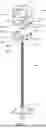
FIG. 1 shows an exploded isometric view of an earthquake anchor according to the first embodiment of this invention.
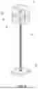
FIG. 2 shows an isometric view of an earthquake anchor according to the first embodiment of this invention.
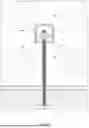
FIG. 3 shows an elevation view of an earthquake anchor according to the first embodiment of this invention installed in an MPP.
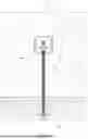
FIG. 4 shows an elevation view of an earthquake anchor according to the first embodiment of this invention installed in the MPP, with an earthquake force acting on the MPP.
FIG. 5 shows an elevation view of an earthquake anchor according to the first embodiment of this invention installed in the MPP, with a fuse plate deformed by the earthquake force.
FIG. 6 shows an exploded isometric view of an earthquake anchor according to the second embodiment of this invention.
FIG. 7 shows an isometric view of an earthquake anchor according to the second embodiment of this invention.
FIG. 8 shows an elevation view of an earthquake anchor according to the second embodiment of this invention installed in an MPP.
FIG. 9 shows an elevation view of an earthquake anchor according to the second embodiment of this invention installed in the MPP, with an earthquake force acting on the MPP.
FIG. 10 shows an elevation view of an earthquake anchor according to the second embodiment of this invention installed in the MPP, with a fuse plate deformed by the earthquake force.
FIG. 11 shows an exploded isometric view of fuse plates according to an alternative embodiment of this invention.
DETAILED DESCRIPTION OF THE PREFERRED EMBODIMENT
This invention will be better understood with reference to FIG. 1 through FIG. 10. The same numerals indicate the same elements in all drawing figures.
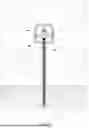
Viewing, simultaneously, FIG. 1 and FIG. 2, numeral 10 indicates a top C-shaped member. Top C-shaped member 10 comprises downward arms indicated by numeral 10a. Downward arms 10a terminate in downward facing flanges indicated by numeral 10b.
Numeral 20 indicates a bottom C-shaped member. Bottom C-shaped member 20 comprises a base indicated by numeral 20a and upward arms indicated by numeral 20b. Upward arms 20b terminate in upward facing flanges indicated by numeral 20c.
Numeral 30 indicates a fuse plate. Fuse plate 30 is clamped between downward facing flanges 10b and upward facing flanges 20c. Fuse plate 30 is disposed substantially parallel to the floor, such that top C-shaped member 10, bottom C-shaped member 20 and fuse plate 30 form a substantially rectangular frame in this embodiment of the invention. The preferred embodiment shows one fuse plate 30, however, several fuse plates 30 can be stacked one on top of the other as shown in FIG. 11.
Numeral 40 indicates a threaded bolt. Threaded bolt 40 comprises a proximate end indicated by numeral 40a and a distal end indicated by numeral 40b. Distal end 40b is affixed to a floor by way of attachment means indicated by numeral 50. Threaded bolt 40 is disposed substantially perpendicularly to the floor.
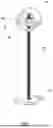
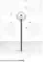
Viewing now FIG. 3, the frame formed by top C-shaped member 10, bottom C-shaped member 20 and fuse plate 30 is configured to be mounted in a rectangular opening formed in the mass plywood panel, the frame adapted to snugly fit therein. Threaded bolt 40 is configured to be inserted in a vertical bore formed in the mass plywood panel, the vertical bore communicating with the rectangular opening.
Viewing again, simultaneously, FIG. 1 and FIG. 2, fuse plate 30 comprises a first opening indicated by numeral 30a. First opening 30a is disposed substantially in the middle of fuse plate 30. Base 20a comprises a second opening indicated by numeral 20d. First opening 30a, second opening 20d and the vertical bore are aligned. First opening 30a and second opening 20d receive proximal end 40a.
In the preferred embodiment, first opening 30a is shown as round hole. However, first opening 30a can be an elongated slot as shown in FIG. 11.
Numeral 60 indicates a nut. A pair of nuts 60 are threaded on threaded bolt 40 and disposed on either side of fuse plate 30, abutting fuse plate 30.
In the preferred embodiment shown in FIG. 1 through FIG. 5, top C-shaped member 10 is larger (i.e. it has longer downward arms 10a) than bottom C-shaped member 20 (which has shorter upward arms 20b than downward arms 10a). This is done for the convenience of assembly and removal of fuse plate 30.
Viewing now FIG. 4, numeral 70 indicates the force of earthquake acting upon the mass plywood panel. Viewing now FIG. 5, fuse plate 30 is shown deformed as a result of the force of earthquake 70, while the mass plywood panel remains intact. The deformed fuse plate 30 would be removed and replaced with a new fuse plate 30.
The second embodiment of this invention shown in FIG. 6 through FIG. 10 is identical to the first embodiment shown in FIG. 1 through FIG. 5, except the shape of the frame formed by top C-shaped member 10, bottom C-shaped member 20 and fuse plate 30 is circular rather than rectangular.
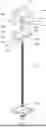
Specifically, viewing, simultaneously, FIG. 6 and FIG. 7, numeral 10 indicates a top C-shaped member. Top C-shaped member 10 comprises downward arms indicated by numeral 10a. Downward arms 10a terminate in downward facing flanges indicated by numeral 10b.
Numeral 20 indicates a bottom C-shaped member. Bottom C-shaped member 20 comprises a base indicated by numeral 20a and upward arms indicated by numeral 20b. Upward arms 20b terminate in upward facing flanges indicated by numeral 20c.
Numeral 30 indicates a fuse plate. Fuse plate 30 is clamped between downward facing flanges 10b and upward facing flanges 20c. Fuse plate 30 is disposed substantially parallel to the floor, such that top C-shaped member 10, bottom C-shaped member 20 and fuse plate 30 form a substantially circular frame in this embodiment of the invention. The preferred embodiment shows one fuse plate 30, however, several fuse plates 30 can be stacked one on top of the other as shown in FIG. 11.
Numeral 40 indicates a threaded bolt. Threaded bolt 40 comprises a proximate end indicated by numeral 40a and a distal end indicated by numeral 40b. Distal end 40b is affixed to a floor by way of attachment means indicated by numeral 50. Threaded bolt 40 is disposed substantially perpendicularly to the floor.
Viewing now FIG. 8, the frame formed by top C-shaped member 10, bottom C-shaped member 20 and fuse plate 30 is configured to be mounted in a rectangular opening formed in the mass plywood panel, the frame adapted to snugly fit therein. Threaded bolt 40 is configured to be inserted in a vertical bore formed in the mass plywood panel, the vertical bore communicating with the rectangular opening.
Viewing again, simultaneously, FIG. 6 and FIG. 7, fuse plate 30 comprises a first opening indicated by numeral 30a. First opening 30a is disposed substantially in the middle of fuse plate 30. Base 20a comprises a second opening indicated by numeral 20d. First opening 30a, second opening 20d and the vertical bore are aligned. First opening 30a and second opening 20d receive proximal end 40a.
In the preferred embodiment, first opening 30a is shown as round hole. However, first opening 30a can be an elongated slot as shown in FIG. 11.
Numeral 60 indicates a nut. A pair of nuts 60 are threaded on threaded bolt 40 and disposed on either side of fuse plate 30, abutting fuse plate 30. 20)
In the preferred embodiment shown in FIG. 6 through FIG. 10, top C-shaped member 10 is larger (i.e. it has longer downward arms 10a) than bottom C-shaped member 20 (which has shorter upward arms 20b than downward arms 10a). This is done for the convenience of assembly and removal of fuse plate 30.
Viewing now FIG. 9, numeral 70 indicates the force of earthquake acting upon the mass plywood panel. Viewing now FIG. 10, fuse plate 30 is shown deformed as a result of the force of earthquake 70, while the mass plywood panel remains intact. The deformed fuse plate 30 would be removed and replaced with a new fuse plate 30.
While the present invention has been described and defined by reference to the preferred embodiment of the invention, such reference does not imply a limitation on the invention, and no such limitation is to be inferred. The invention is capable of considerable modification, alteration, and equivalents in form and function, as will occur to those ordinarily skilled and knowledgeable in the pertinent arts. The depicted and described preferred embodiment of the invention is exemplary only, and is not exhaustive of the scope of the invention. Consequently, the invention is intended to be limited only by the spirit and scope of the appended claims, giving full cognizance to equivalents in all respects.
Claims
We claim:1. An earthquake anchor for a mass plywood panel comprising:
a top C-shaped member comprising downward arms terminating in downward facing flanges;
a bottom C-shaped member comprising a base and upward arms terminating in upward facing flanges;
at least one fuse plate clamped between the downward facing flanges and upward facing flanges, the fuse plate disposed substantially parallel to the floor, such that the top C-shaped member, the bottom C-shaped member and the fuse plate form a substantially rectangular frame;
a threaded bolt comprising a proximate end and a distal end, the distal end affixed to a floor by way of attachment means, the threaded bolt disposed substantially perpendicularly to the floor;
wherein the frame configured to be mounted in a rectangular opening formed in the mass plywood panel, the frame adapted to snugly fit therein;
wherein the threaded bolt configured to be inserted in a vertical bore formed in the mass plywood panel, the vertical bore communicating with the rectangular opening;
wherein the fuse plate comprising a first opening disposed substantially in the middle of the fuse plate;
wherein the base comprising a second opening, such that the first opening, the second opening and the vertical bore are aligned, the first opening and the second opening receiving the proximal end;
wherein a pair of nuts threaded on the threaded bolt and disposed on either side of the fuse plate abutting the fuse plate.
2. An earthquake anchor for a mass plywood panel comprising:
a top C-shaped member comprising downward arms terminating in downward facing flanges;
a bottom C-shaped member comprising a base and upward arms terminating in upward facing flanges;
at least one fuse plate clamped between the downward facing flanges and upward facing flanges, the fuse plate disposed substantially parallel to the floor, such that the top C-shaped member, the bottom C-shaped member and the fuse plate form a substantially circular frame;
a threaded bolt comprising a proximate end and a distal end, the distal end affixed to a floor by way of attachment means, the threaded bolt disposed substantially perpendicularly to the floor;
wherein the frame configured to be mounted in a circular opening formed in the mass plywood panel, the frame adapted to snugly fit therein;
wherein the threaded bolt configured to be inserted in a vertical bore formed in the mass plywood panel, the vertical bore communicating with the circular opening;
wherein the fuse plate comprising a first opening disposed substantially in the middle of the fuse plate;
wherein the base comprising a second opening, such that the first opening, the second opening and the vertical bore are aligned, the first opening and the second opening receiving the proximal end;
wherein a pair of nuts threaded on the threaded bolt and disposed on either side of the fuse plate abutting the fuse plate.
Images & Drawings included:


Sources:
- United States Patent and Trademark Office - verify current appl. status at the USPTO↗
Recent applications in this class:
- » 20260103912 2026-04-16
ROCKING SELF-CENTERING SEISMIC AND VIBRATION PREVENTION STRUCTURE FACILITATING OVERALL REGULATION - » 20260049497 2026-02-19
ENERGY DISSIPATOR FOR TRACTIVE LOADS - » 20250361741 2025-11-27
Building System Capable of Withstanding Strong Winds, Earthquakes, Flooding, and Other Natural Disasters - » 20250305316 2025-10-02
STRUCTURAL SLIDING BEARING - » 20250283343 2025-09-11
SEISMIC WALL FUSE - » 20250270837 2025-08-28
REINFORCED BUILDING WALL USING COMPRESSION ROD - » 20250154788 2025-05-15
DIRECTION-ADJUSTABLE BOLTED SPHERICAL JOINT FOR COLLAPSE RESISTANCE AND EARTHQUAKE RESISTANCE - » 20250137275 2025-05-01
SEISMIC ANCHOR SYSTEM, APPARATUS, AND STRUCTURE INCLUDING SAME - » 20250092708 2025-03-20
SEISMIC-RESISTANT JOINT STRUCTURE OF PC COLUMN AND PC BEAM USING STEEL BRACKET - » 20240426125 2024-12-26
COMPOSITE MATERIAL REINFORCEMENT DEVICE FOR BOX-TYPE CONCRETE STRUCTURE AND METHOD OF CONSTRUCTING THE SAME