OPERATION SUPPORT APPARATUS, OPERATION SUPPORT SYSTEM, OPERATION SUPPORT METHOD, AND NON-TRANSITORY COMPUTER READABLE MEDIUM
US20260043161A1
2026-02-12
19/363,620
2025-10-20
Smart Summary: An operation support apparatus helps manage how an electrolyzer works by calculating its operating conditions. It first estimates how the electrolyzer's performance might change. Then, based on this estimate, it calculates a new operating condition to ensure the electrolyzer uses a specific amount of power or produces a certain amount of product within a set time. The operating conditions include various factors that affect how the electrolyzer operates. This system aims to improve efficiency and performance in electrolyzer operations. 🚀 TL;DR
Abstract:
Provided is an operation support apparatus including a calculation unit which calculates an operating condition of an electrolyzer based on a first estimated value of a performance change in electrolytic performance in the electrolyzer. The operation support apparatus may further include an estimation unit which estimates a second estimated value of the performance change based on a first operating condition that is the operating condition calculated by the calculation unit. The calculation unit may calculate, based on the second estimated value, a second operating condition that is the operating condition under which a power consumption amount of the electrolyzer in a predetermined certain period becomes a predetermined power amount or a production amount of a product produced by the electrolyzer in the certain period becomes a predetermined production amount. The operating condition may include a plurality of parameters related to operation of the electrolyzer.
Inventors:
- HIROAKI YOSHINO 11 🇯🇵 Tokyo, Japan
- Takeaki SASAKI 7 🇯🇵 Tokyo, Japan
- Akihito ISHII 2 🇯🇵 Tokyo, Japan
Applicant:
Interested in similar patents?
Get notified when new applications in this technology area are published.
Classification:
C25B15/023 » CPC main
Operating or servicing cells; Process control or regulation Measuring, analysing or testing during electrolytic production
Description
The contents of the following patent application(s) are incorporated herein by reference:
-
- NO. 2023-084339 filed in JP on May 23, 2023
- NO. PCT/JP2024/018857 filed in WO on May 22, 2024.
BACKGROUND
1. Technical Field
The present invention relates to an operation support apparatus, an operation support system, an operation support method, and a non-transitory computer readable medium.
2. Related Art
Patent Document 1 describes that “the current calculation unit 55 calculates the current at which the production amount Pa of the product P produced by the plurality of electrolyzers 90 in the period T is maximized, . . . ” (Paragraph 0093). Patent Document 2 describes that “the estimation unit estimates the performance degradation rate based on the concentration profile” (claim 1).
RELATED ART DOCUMENTS
Patent Documents
-
- Patent Document 1: International Publication No. 2022/191082
- Patent Document 2: Japanese Patent No. 7182025
BRIEF DESCRIPTION OF THE DRAWINGS
FIG. 1 is a diagram illustrating an example of an electrolytic apparatus 200 according to one embodiment of the present invention.
FIG. 2 is a diagram illustrating an example of one electrolyzer 90 in FIG. 1.
FIG. 3 is a diagram illustrating an example of details of one electrolysis cell 91 in FIG. 2.
FIG. 4 is a view of the ion exchange membrane 84 of FIG. 3 as viewed in a Y axis direction.
FIG. 5 is an enlarged view of a vicinity of an ion exchange membrane 84 in the electrolysis cell 91 illustrated in FIG. 3.
FIG. 6 is a block diagram of an operation support apparatus 100 and a diagram illustrating an example of an operation support system 300 according to one embodiment of the present invention.
FIG. 7 is a diagram illustrating an example of a relationship between an accumulation amount of an impurity Im and current efficiency CE for each impurity Im.
FIG. 8 is a diagram illustrating an example of a relationship between an elastic deformation amount of a gasket 85 and the current efficiency CE.
FIG. 9 is a diagram illustrating an example of a relationship between a remaining amount of a metallic coating agent on a surface of a cathode 82 and a surface of an anode 80 and a voltage CV of the electrolyzer 90 for each material of the coating agent.
FIG. 10 is a diagram illustrating an example of a first set value Vs1 of a parameter Pr2 when there are a plurality of electrolyzers 90.
FIG. 11 is a diagram illustrating another example of the first set value Vs1 of the parameter Pr2 when there are the plurality of electrolyzers 90.
FIG. 12 is a diagram illustrating an example of a relationship between an estimated value VL in an electrolyzer 90-1 and time.
FIG. 13 is a diagram illustrating an example of a relationship between the estimated value VL in an electrolyzer 90-2 and the time.
FIG. 14 is a diagram illustrating another example of the relationship between the estimated value VL in the electrolyzer 90-1 and the time.
FIG. 15 is a diagram illustrating another example of the relationship between the estimated value VL in the electrolyzer 90-2 and the time.
FIG. 16 is a diagram illustrating an example of estimation of the estimated value VL.
FIG. 17 is a diagram illustrating another example of the estimation of the estimated value VL.
FIG. 18 is a diagram illustrating an example of candidates for an operating condition Cd.
FIG. 19 is a flowchart illustrating an example of an operation support method according to one embodiment of the present invention.
FIG. 20 is a flowchart illustrating another example of the operation support method according to one embodiment of the present invention.
FIG. 21 is a flowchart illustrating another example of the operation support method according to one embodiment of the present invention.
FIG. 22 is a flowchart illustrating another example of the operation support method according to one embodiment of the present invention.
FIG. 23 is a flowchart illustrating another example of the operation support method according to one embodiment of the present invention.
FIG. 24 is a diagram illustrating an example of a computer 2200 in which the operation support apparatus 100 according to one embodiment of the present invention may be entirely or partially embodied.
DESCRIPTION OF EXEMPLARY EMBODIMENTS
The present invention will be described below through embodiments of the invention, but the following embodiments do not limit the invention according to the claims. In addition, not all combinations of features described in the embodiments are essential to a solution of the invention.
FIG. 1 is a diagram illustrating an example of an electrolytic apparatus 200 according to one embodiment of the present invention. The electrolytic apparatus 200 of the present example includes a plurality of electrolyzers 90 (an electrolyzer 90-1 to an electrolyzer 90-M (M is an integer of 2 or more)). The electrolyzer 90 electrolyzes an electrolyte. The electrolytic apparatus 200 of the present example includes an inlet tube 92, an inlet tube 93, an outlet tube 94, and an outlet tube 95. The inlet tube 92 and the inlet tube 93 are connected to each of the plurality of electrolyzers 90. The outlet tube 94 and the outlet tube 95 are connected to each of the plurality of electrolyzers 90.
The electrolytic apparatus 200 electrolyzes an electrolyte. The electrolyzer 90 electrolyzes an electrolyte. The electrolyte is, for example, a NaCl (sodium chloride) aqueous solution. In the present specification, a case where the electrolyte is a NaCl (sodium chloride) aqueous solution is referred to as brine electrolysis. In the case of brine electrolysis, the electrolyzer 90 generates Cl2 (chlorine) by electrolyzing a NaCl (sodium chloride) aqueous solution in an anode chamber 79 (described later), and generates NaOH (sodium hydroxide) and H2 (hydrogen) by electrolyzing H2O (water) in a cathode chamber 98 (described later).
The electrolyte electrolyzed in the electrolyzer 90 may be a NaOH (sodium hydroxide) aqueous solution or a KOH (potassium hydroxide) aqueous solution. In the present specification, a case where the electrolyte is a NaOH (sodium hydroxide) aqueous solution or a KOH (potassium hydroxide) aqueous solution is referred to as alkaline water electrolysis. In the case of alkaline water electrolysis, the electrolyzer 90 generates O2 (oxygen) and H2 (hydrogen) by electrolyzing a NaOH (sodium hydroxide) aqueous solution or a KOH (potassium hydroxide) aqueous solution.
A first aqueous solution 70 is introduced into each of the plurality of electrolyzers 90. The first aqueous solution 70 may be introduced into each of the plurality of electrolyzers 90 after passing through the inlet tube 92. In the case of brine electrolysis, the first aqueous solution 70 is an aqueous solution of alkali metal chloride. An alkali metal is an element belonging to Group 1 of the periodic table. The first aqueous solution 70 may be a NaCl (sodium chloride) aqueous solution or a KCl (potassium chloride) aqueous solution. In the present example, the first aqueous solution 70 is a NaCl (sodium chloride) aqueous solution. In the case of alkaline water electrolysis, the first aqueous solution 70 is a NaOH (sodium hydroxide) aqueous solution or a KOH (potassium hydroxide) aqueous solution.
A second aqueous solution 72 is introduced into each of the plurality of electrolyzers 90. The second aqueous solution 72 may be introduced into each of the plurality of electrolyzers 90 after passing through the inlet tube 93. The second aqueous solution 72 is an aqueous solution of alkali metal hydroxide. In the case of brine electrolysis, the second aqueous solution 72 is a NaOH (sodium hydroxide) aqueous solution or a KOH (potassium hydroxide) aqueous solution. In the case of alkaline water electrolysis, the second aqueous solution 72 is a NaOH (sodium hydroxide) aqueous solution or a KOH (potassium hydroxide) aqueous solution.
A third aqueous solution 74 and a gas 77 (described later) are discharged from each of the plurality of electrolyzers 90. The third aqueous solution 74 and the gas 77 (described later) may be discharged to an outside of the electrolytic apparatus 200 after passing through the outlet tube 94. In the case of brine electrolysis, the third aqueous solution 74 is an aqueous solution of alkali metal chloride. When the first aqueous solution 70 is a NaCl (sodium chloride) aqueous solution, the third aqueous solution 74 is a NaCl (sodium chloride) aqueous solution. When the first aqueous solution 70 is a KCl (potassium chloride) aqueous solution, the third aqueous solution 74 is a KCl (potassium chloride) aqueous solution. When the first aqueous solution 70 is a NaCl (sodium chloride) aqueous solution or a KCl (potassium chloride) aqueous solution, the gas 77 (described later) is Cl2 (chlorine). In the case of water electrolysis, the first aqueous solution 70 is a NaOH (sodium hydroxide) aqueous solution or a KOH (potassium hydroxide) aqueous solution. When the first aqueous solution 70 is a NaOH (sodium hydroxide) aqueous solution, the third aqueous solution 74 is a NaOH (sodium hydroxide) aqueous solution. When the first aqueous solution 70 is a KOH (potassium hydroxide) aqueous solution, the third aqueous solution 74 is a KOH (potassium hydroxide) aqueous solution.
A fourth aqueous solution 76 and a gas 78 (described later) are discharged from each of the plurality of electrolyzers 90. The fourth aqueous solution 76 and the gas 78 (described later) may be discharged to the outside of the electrolytic apparatus 200 after passing through the outlet tube 95. The fourth aqueous solution 76 is an aqueous solution of alkali metal hydroxide. When the second aqueous solution 72 is a NaOH (sodium hydroxide) aqueous solution, the fourth aqueous solution 76 is a NaOH (sodium hydroxide) aqueous solution. When the second aqueous solution 72 is a KOH (potassium hydroxide) aqueous solution, the fourth aqueous solution 76 is a KOH (potassium hydroxide) aqueous solution. The gas 78 (described later) is H2 (hydrogen).
FIG. 2 is a diagram illustrating an example of one electrolyzer 90 in FIG. 1. The electrolyzer 90 may include a plurality of electrolysis cells 91 (an electrolysis cell 91-1 to an electrolysis cell 91-N (N is an integer of 2 or more)). N is 50, for example. In the present example, each of the electrolyzer 90-1 to the electrolyzer 90-M (see FIG. 1) includes the plurality of electrolysis cells 91.
In the present example, the inlet tube 92 and the inlet tube 93 are connected to each of the electrolysis cell 91-1 to the electrolysis cell 91-N. The first aqueous solution 70 is introduced into each of the electrolysis cell 91-1 to the electrolysis cell 91-N. The first aqueous solution 70 may be introduced into each of the electrolysis cell 91-1 to the electrolysis cell 91-N after passing through the inlet tube 92. The second aqueous solution 72 is introduced into each of the electrolysis cell 91-1 to the electrolysis cell 91-N. The second aqueous solution 72 may be introduced into each of the electrolysis cell 91-1 to the electrolysis cell 91-N after passing through the inlet tube 93.
In the present example, the outlet tube 94 and the outlet tube 95 are connected to each of the electrolysis cell 91-1 to the electrolysis cell 91-N. The third aqueous solution 74 and the gas 77 (described later) are discharged from each of the electrolysis cell 91-1 to the electrolysis cell 91-N. The third aqueous solution 74 and the gas 77 (described later) may be discharged from each of the electrolysis cell 91-1 to the electrolysis cell 91-N to the outside of the electrolytic apparatus 200 after passing through the outlet tube 94. The fourth aqueous solution 76 and the gas 78 (described later) are discharged from each of the electrolysis cell 91-1 to the electrolysis cell 91-N. The fourth aqueous solution 76 and the gas 78 (described later) may be discharged from each of the electrolysis cell 91-1 to the electrolysis cell 91-N to the outside of the electrolytic apparatus 200 after passing through the outlet tube 95.
FIG. 3 is a diagram illustrating an example of details of one electrolysis cell 91 in FIG. 2. The electrolyzer 90 includes the anode chamber 79, an anode 80, the cathode chamber 98, a cathode 82, and an ion exchange membrane 84, and a gasket 85. In the present example, one electrolysis cell 91 includes the anode chamber 79, the anode 80, the cathode chamber 98, the cathode 82, the ion exchange membrane 84, and the gasket 85. The anode chamber 79 and the cathode chamber 98 are provided inside the electrolysis cell 91. The anode chamber 79 and the cathode chamber 98 are partitioned by the ion exchange membrane 84. The anode 80 is arranged in the anode chamber 79. The cathode 82 is arranged in the cathode chamber 98. The gasket 85 holds the ion exchange membrane 84. The gasket 85 prevents a liquid 73 and a liquid 75 from leaking to an outside of the electrolysis cell 91 by holding the ion exchange membrane 84. In the present example, a gasket 85-1 and a gasket 85-2 sandwich the ion exchange membrane 84.
The electrolyzer 90 may have at least one of a temperature sensor 96 or a temperature sensor 97. The temperature sensor 96 measures a temperature T1 of the liquid 73 (described later). The temperature sensor 97 measures a temperature T2 of the liquid 75 (described later). At least one of the temperature T1 measured by the temperature sensor 96 or the temperature T2 measured by the temperature sensor 97 may be transmitted to a control unit 60 (described later).
The inlet tube 92 and the outlet tube 94 are connected to the anode chamber 79. The inlet tube 93 and the outlet tube 95 are connected to the cathode chamber 98. In the present example, the inlet tube 92 and the inlet tube 93 are connected to a bottom surface 87, and the outlet tube 94 and the outlet tube 95 are connected to a ceiling surface 88. The first aqueous solution 70 is introduced into the anode chamber 79. The second aqueous solution 72 is introduced into the cathode chamber 98. The third aqueous solution 74 is discharged from the anode chamber 79. The fourth aqueous solution 76 is discharged from the cathode chamber 98.
The ion exchange membrane 84 is a film-shaped substance which prevents passage of ions having a same sign as ions arranged in the ion exchange membrane 84 and allows passage of ions having a different sign therefrom. In the case of brine electrolysis, the ion exchange membrane 84 is a membrane which allows Na+ (sodium ion) to pass therethrough and prevents OH− (hydroxide ion) and Cl− (chloride ion) from passing therethrough.
The anode 80 and the cathode 82 may be maintained at predetermined positive and negative potentials, respectively. The first aqueous solution 70 introduced into the anode chamber 79 and the second aqueous solution 72 introduced into the cathode chamber 98 are electrolyzed by a potential difference between the anode 80 and the cathode 82. In each case of brine electrolysis and alkaline water electrolysis, following chemical reactions take place at the anode 80.
2Cl−→Cl2+2e− Chemical Formula 1-1 (Brine electrolysis)
4OH−≥O2+2H2O+4e− Chemical Formula 1-2 (Alkaline water electrolysis)
When the first aqueous solution 70 is a NaCl (sodium chloride) aqueous solution, NaCl (sodium chloride) dissociates into Na+ (sodium ion) and Cl− (chloride ion) in the first aqueous solution 70. In the anode 80, a Cl2 (chlorine) gas is generated by the chemical reaction represented by Chemical Formula 1-1. The gas 77 (the Cl2 (chlorine) gas) and the third aqueous solution 74 may be discharged from the anode chamber 79. By the attractive force from the cathode 82, Na+ (sodium ion) moves from the anode chamber 79 via the ion exchange membrane 84 and then to the cathode chamber 98.
When the first aqueous solution 70 is a NaOH (sodium hydroxide) aqueous solution, NaOH (sodium hydroxide) dissociates into Na+ (sodium ion) and OH− (hydroxide ion) in the first aqueous solution 70. In the anode 80, H2O (water) and an O2 (oxygen) gas are generated by the chemical reaction represented by Chemical Formula 1-2. The gas 77 (the O2 (oxygen) gas) and the third aqueous solution 74 (the H2O (water)) may be discharged from the anode chamber 79. By the attractive force from the cathode 82, Na+ (sodium ion) moves from the anode chamber 79 via the ion exchange membrane 84 and then to the cathode chamber 98.
The liquid 73 may remain in the anode chamber 79. The liquid 73 may be an aqueous solution of alkali metal chloride. In the case of brine electrolysis, the liquid 73 is a NaCl (sodium chloride) aqueous solution or a KCl (potassium chloride) aqueous solution. When the liquid 73 is a NaCl (sodium chloride) aqueous solution, a Na+ (sodium ion) concentration and a Cl− (chloride ion) concentration of the liquid 73 may be smaller than a Na+ (sodium ion) concentration and a Cl− (chloride ion) concentration of the first aqueous solution 70. When the liquid 73 is a KCl (potassium chloride) aqueous solution, a K+ (potassium ion) concentration and a Cl− (chloride ion) concentration of the liquid 73 may be smaller than a K+ (potassium ion) concentration and a Cl− (chloride ion) concentration of the first aqueous solution 70. In the case of alkaline water electrolysis, the liquid 73 is a NaOH (sodium hydroxide) aqueous solution or a KOH (potassium hydroxide) aqueous solution.
In the cathode 82, a following chemical reaction occurs.
2H2O+2e−→H2+2OH− Chemical Formula 2
When the second aqueous solution 72 is a NaOH (sodium hydroxide) aqueous solution, NaOH (sodium hydroxide) dissociates into Na+ (sodium ion) and OH− (hydroxide ion) in the second aqueous solution 72. In the cathode 82, a H2 (hydrogen) gas and OH− (hydroxide ion) are generated by the chemical reaction represented by Chemical Formula 2. The gas 78 (the H2 (hydrogen) gas) and the fourth aqueous solution 76 may be discharged from the cathode chamber 98. A case where the second aqueous solution 72 is a KOH (potassium hydroxide) aqueous solution is also similar thereto.
The liquid 75 may remain in the cathode chamber 98. The liquid 75 may be an aqueous solution of alkali metal hydroxide. In the present example, the liquid 75 is a NaOH (sodium hydroxide) aqueous solution or a KOH (potassium hydroxide) aqueous solution. In the case of brine electrolysis, the liquid 75 in which OH− (hydroxide ion) generated by the chemical reaction represented by Chemical Formula 2 and Na+ (sodium ion) moved from the anode chamber 79 are dissolved remains in the cathode chamber 98.
FIG. 4 is a view of the ion exchange membrane 84 of FIG. 3 as viewed in a Y axis direction. The gasket 85 of the present example is a frame-shaped member which holds an edge of the ion exchange membrane 84 in an XZ plane. In FIG. 4, the gasket 85 is indicated by hatching. When viewed in the Y axis direction, the gasket 85 may be arranged so as to surround the ion exchange membrane 84. A lower end 61 of the gasket 85 may be connected to the bottom surface 87 (see FIG. 3), and an upper end 62 may be connected to the ceiling surface 88 (see FIG. 3). One end 63 in an X axis direction of the gasket 85 may be connected to one inner surface which is one inner surface of the electrolysis cell 91 (see FIG. 3) and intersects with the X axis direction. Another end 64 in the X axis direction of the gasket 85 may be connected to another inner surface which is another inner surface of the electrolysis cell 91 (see FIG. 3) and intersects with the X axis direction.
FIG. 5 is an enlarged view of a vicinity of the ion exchange membrane 84 in the electrolysis cell 91 illustrated in FIG. 3. In FIG. 5, the gasket 85 of FIG. 4 is omitted. An anion group 86 is fixed to the ion exchange membrane 84 of the present example. Since anions are repelled by the anion group 86, the anions hardly pass through the ion exchange membrane 84. In the present example, the anions are OH− (hydroxide ion) and Cl− (chloride ion). Since a cation 71 is not repelled by the anion group 86, the cation 71 can pass through the ion exchange membrane 84. When the first aqueous solution 70 (see FIG. 3) is a NaCl (sodium chloride) aqueous solution, the cation 71 is Na+ (sodium ion).
FIG. 6 is a block diagram of an operation support apparatus 100 and a diagram illustrating an example of an operation support system 300 according to one embodiment of the present invention. The operation support apparatus 100 supports operation of the electrolyzer 90 (see FIG. 2). The operation support apparatus 100 includes a calculation unit 10. The operation support apparatus 100 may include an estimation unit 20, a selection unit 22, an input unit 30, an output unit 32, a storage unit 40, a current supply unit 50, and the control unit 60. The input unit 30 is, for example, a keyboard, a mouse, or the like. The output unit 32 is, for example, a display, a monitor, or the like.
The operation support system 300 includes the operation support apparatus 100 and the electrolyzer 90. The control unit 60 may transmit, to the electrolyzer 90, a control signal Sc for controlling the electrolyzer 90. The control unit 60 may wirelessly transmit the control signal Sc. The electrolyzer 90 may transmit a control signal Sc′ to the control unit 60. The electrolyzer 90 may wirelessly transmit the control signal Sc′. The control signal Sc′ may include at least one of the temperature T1 (described later) of the liquid 73 or the temperature T2 (described later) of the liquid 75. In FIG. 6, a range of the operation support apparatus 100 is indicated by a broken line, and a range of the operation support system 300 is indicated by a one-dot chain line.
A part or a whole of the operation support apparatus 100 is, as an example, a computer including a CPU, a memory, an interface, or the like. The control unit 60 may be the CPU. The calculation unit 10, the estimation unit 20, and the control unit 60 may be one corresponding CPU. When the operation support apparatus 100 is a computer, an operation support program for causing the computer to function as the operation support apparatus 100 or the operation support system 300 may be installed in the computer, and an operation support program for executing an operation support method to be described later may be installed in the computer.
An estimated value of a performance change in electrolytic performance in the electrolyzer 90 is defined as an estimated value VL. The performance change in the electrolytic performance in the electrolyzer 90 may be a performance change of the ion exchange membrane 84, the anode 80, the cathode 82, or the gasket 85 included in the electrolyzer 90. The estimated value VL may be an estimated value of performance degradation or an estimated value of performance enhancement.
The calculation unit 10 calculates an operating condition of the electrolyzer 90 (see FIG. 2) based on a first estimated value of the performance change in the electrolytic performance in the electrolyzer 90. The first estimated value is defined as a first estimated value VL1. The operating condition is defined as an operating condition Cd. The operating condition Cd refers to an operating status of the electrolyzer 90 that can affect a state of the ion exchange membrane 84, the anode 80, the cathode 82, or the gasket 85. The first estimated value VL1 is an estimated value of the performance change of the ion exchange membrane 84, the anode 80, the cathode 82, or the gasket 85 after a time point when the calculation unit 10 calculates the operating condition Cd. Accordingly, the calculation unit 10 can calculate the operating condition Cd in consideration of the performance change of the ion exchange membrane 84, the anode 80, the cathode 82, or the gasket 85.
The electrolyzer 90 electrolyzes the first aqueous solution 70. Therefore, one or more impurities can accumulate in the ion exchange membrane 84 as a running time of the electrolyzer 90 elapses. The impurities accumulated in the ion exchange membrane 84 are defined as impurities Im. The impurities Im may be compounds or elements. The one or more impurities Im may refer to one or more types of impurities Im.
The performance change in the electrolytic performance may refer to a performance change of the ion exchange membrane 84, and may refer to a performance change of the gasket 85. The performance change of the ion exchange membrane 84 may refer to a performance change due to accumulation of the impurity Im in the ion exchange membrane 84 or occurrence of perforation in the ion exchange membrane 84. The performance change of the gasket 85 may refer to a performance change due to corrosion of the gasket 85. When the gasket 85-1 and the gasket 85-2 sandwich the ion exchange membrane 84 (see FIG. 3), the liquid 73 may be penetrated between the gasket 85-1 and the ion exchange membrane 84 in the Y axis direction, or the liquid 75 may be penetrated between the gasket 85-2 and the ion exchange membrane 84 in the Y axis direction. Accordingly, the liquid 73 or the liquid 75 may permeate the gasket 85. Accordingly, the gasket 85 may corrode.
The performance change in the electrolytic performance in the electrolyzer 90 may include performance degradation and performance enhancement in the electrolytic performance. The performance degradation and the performance enhancement in the electrolytic performance may refer to performance degradation and performance enhancement of the ion exchange membrane 84 or the gasket 85. When the impurity Im accumulates in the ion exchange membrane 84, the performance of the ion exchange membrane 84 is likely to be degraded. However, when the operating condition Cd of the electrolyzer 90 changes, at least a part of the impurity Im accumulated in the ion exchange membrane 84 may be removed. In such a case, the performance of the ion exchange membrane 84 can be enhanced.
When an elastic deformation amount (described later) of the gasket 85 decreases, the performance of the gasket 85 is likely to be degraded. However, when the operating condition Cd of the electrolyzer 90 changes, the liquid 73 that has been penetrated between the gasket 85-1 and the ion exchange membrane 84 in the Y axis direction or the liquid 75 that has been penetrated between the gasket 85-2 and the ion exchange membrane 84 in the Y axis direction may be removed. For example, when the temperature T1 of the liquid 73 (see FIG. 3) or the temperature T2 of the liquid 75 (see FIG. 3) increases, the gasket 85 may expand. When the gasket 85 expands, the elastic deformation amount (described later) of the gasket 85 may increase. When the elastic deformation amount (described later) of the gasket 85 increases, the liquid 73 or the liquid 73 that has penetrated may be removed as described above. In such a case, the performance of the gasket 85 may be enhanced.
Base materials of the cathode 82 and the anode 80 may be Ni (nickel). A surface of the cathode 82 and a surface of the anode 80 may be coated with a coating agent made of metal. The metal is, for example, Pt (platinum) or Ru (ruthenium). The coating agent may be formed by plating. As the running time of the electrolyzer 90 elapses, Pt (platinum) or Ru (ruthenium) provided on the surface of the cathode 82 may be contained in the liquid 75 (see FIG. 3). The impurity Im may include Ni (nickel), Pt (platinum), or Ru (ruthenium).
The estimation unit 20 may estimate the first estimated value VL1 based on an actual value of impurity data regarding an accumulation rate of the impurity Im in the ion exchange membrane 84. The impurity data is defined as impurity data Di. The actual value of the impurity data Di is defined as an actual value Vi. The actual value Vi of the impurity data Di may include an actual value of an accumulation rate or actual value of an accumulation amount of each of one or more elements constituting one or more impurities Im accumulated in the ion exchange membrane 84. The actual value of the accumulation rate or the actual value of the accumulation amount of each of the one or more elements is defined as an actual value Vi′.
The estimation unit 20 may estimate one or more impurities Im based on the actual value Vi′. The estimation unit 20 may estimate types of one or more impurities Im based on the actual value Vi′. When the impurity Im is a compound, the type of the impurity Im refers to a type of the compound. When the impurity Im is an element, the type of the impurity Im refers to a type of the element. The estimation unit 20 may estimate the first estimated value VL1 based on accumulation rates or accumulation amounts of the one or more impurities Im estimated. The estimation unit 20 may estimate the first estimated value VL1 based on accumulation rates or accumulation amounts of the one or more types of impurities Im estimated.
The actual value Vi and the actual value Vi′ may be actual analysis data of the ion exchange membrane 84. The actual analysis data refers to data evaluated by actually analyzing the ion exchange membrane 84. When the impurity Im is a compound, the actual value Vi′ may be actual analysis data of a plurality of elements constituting the compound accumulated in the ion exchange membrane 84, and an accumulation amount or accumulation rate for each of the elements. The actual analysis data may be acquired by actually analyzing the ion exchange membrane 84 detached from the electrolyzer 90 in a state where the operation of the electrolyzer 90 is stopped. The actual analysis data may be acquired by actually analyzing elements contained in the liquid 73 or the liquid 75 leaking from the electrolysis cell 91 in a state where the electrolyzer 90 is operated.
The estimation unit 20 can estimate one or more compounds based on the accumulation amount or accumulation rate of each element actually analyzed. The one or more compounds may refer to one or more types of compounds. The estimation unit 20 can estimate types of one or more compounds based on the accumulation amount or accumulation rate of each element actually analyzed.
When the impurity Im is an element, the actual value Vi′ may be analysis data, for each element, of an accumulation amount or accumulation rate of each of one or more elements accumulated in the ion exchange membrane 84. The estimation unit 20 can estimate one or more elements based on the accumulation amount or accumulation rate of each element actually analyzed. The one or more elements refer to one or more types of elements.
The accumulation amount of each of one or more elements constituting the impurity Im may be an accumulation amount over a predetermined certain period Te. The certain period Te is, for example, one year. The accumulation rate of each of one or more elements constituting the impurity Im may be an accumulation amount per predetermined certain period Te′. The certain period Te′ may be equal to or different from the certain period Te.
The estimation unit 20 may calculate the accumulation rate or accumulation amount of the impurity Im for the one or more impurities Im estimated. The accumulation amount of the impurity Im may be an accumulation amount of the impurity Im over a certain period Te′. The accumulation rate of the impurity Im may be an accumulation amount of the impurity Im per certain period Te′. The estimation unit 20 may calculate the accumulation rate or accumulation amount of the impurity Im for each impurity Im.
The actual value Vi may be evaluated in a state where the ion exchange membrane 84 is removed from the electrolyzer 90, or may be evaluated in a state where the ion exchange membrane 84 is attached to the electrolyzer 90. The actual value Vi′ may be data obtained by analyzing a relationship between the accumulation amount or the accumulation rate of each of the plurality of elements constituting the impurity Im and the running time of the electrolyzer 90 in a state where the ion exchange membrane 84 or the gasket 85 is attached to the electrolyzer 90.
The estimation unit 20 may estimate the first estimated value VL1 based on an actual value of the elastic deformation amount of the gasket 85. When the ion exchange membrane 84 is sandwiched between the gasket 85-1 and the gasket 85-2 (see FIG. 3), a pressing force for sandwiching the ion exchange membrane 84 is applied to the gasket 85-1 and the gasket 85-2. The elastic deformation amount of the gasket 85 refers to a deformation amount of the gasket 85-1 or the gasket 85-2 due to application of this pressing force.
When the gasket 85 is corroded by the liquid 73 or the liquid 75, the elastic deformation amount of the gasket 85 may change. In the example of FIGS. 3 and 4, the elastic deformation amount of the gasket 85 may be a difference between a thickness in the Y axis direction of the gasket 85 before corrosion and a thickness in the Y axis direction of the gasket 85 after corrosion. The thickness in the Y axis direction of the gasket 85 may be an average value or a median value of thicknesses, in the Y axis direction along a periphery of the ion exchange membrane 84 in FIG. 4, of the gasket 85 arranged around the periphery.
The actual value of the elastic deformation amount of the gasket 85 is defined as an actual value Vj. The actual value Vj may be actual analysis data of the elastic deformation amount. The actual analysis data may be acquired by actually analyzing the gasket 85 detached from the electrolyzer 90 in a state where the operation of the electrolyzer 90 is stopped. The actual analysis data may be acquired by actually analyzing elements contained in the liquid 73 or the liquid 75 leaking from the electrolysis cell 91 in a state where the electrolyzer 90 is operated. The actual value Vi and the actual value Vj may be input by the input unit 30. The actual value Vi and the actual value Vj input by the input unit 30 may be stored in the storage unit 40.
In the case of brine electrolysis, when the performance of the ion exchange membrane 84 changes or the gasket 85 corrodes, an alkali metal chloride contained in the liquid 73 may pass through the ion exchange membrane 84. The alkali metal chloride having passed through the ion exchange membrane 84 may be contained in the liquid 75. As described above, in the case of brine electrolysis, the liquid 75 is an aqueous solution of alkali metal hydroxide.
The impurity data Di may include concentration data of the impurity Im in the liquid 73. When the liquid 73 is a NaCl (sodium chloride) aqueous solution, the actual value Vi may be actual analysis data obtained by actually analyzing the concentration of the impurity Im in the NaCl (sodium chloride) aqueous solution.
The first estimated value VL1 is, for example, a decrease rate of the current efficiency CE of the electrolyzer 90. The current efficiency CE refers to a ratio of an actual production amount to a theoretical production amount of a product produced by the electrolyzer 90. The product is defined as a product P. A theoretical production amount of the product P is defined as a production amount Pa. An actual production amount of the product P is defined as a production amount Pr. The current efficiency CE refers to a ratio of the production amount Pr to the production amount Pa. The current efficiency CE is likely to decrease as the accumulation amount of the impurity Im in the ion exchange membrane 84 increases. The first estimated value VL1 may be an increase rate of the voltage CV of the electrolyzer 90. The voltage CV is likely to increase as the accumulation amount of the impurity Im in the ion exchange membrane 84 increases.
FIG. 7 is a diagram illustrating an example of a relationship between the accumulation amount of the impurity Im and the current efficiency CE for each impurity Im. FIG. 7 illustrates a relationship between the accumulation amount of the impurity Im and the current efficiency CE for each of four impurities Im (an impurity Im1 to an impurity Im4). Types of the impurity Im1 to the impurity Im4 are different from each other. The impurity Im1 is, for example, a compound of Ba (barium) and I (iodine). The impurity Im2 is, for example, a compound of Ca (calcium), Sr (strontium), and I (iodine). The impurity Im3 is, for example, I (iodine). The impurity Im4 is, for example, a compound of Si (silicon) and Al (aluminum).
As illustrated in FIG. 7, the current efficiency CE is likely to decrease as the accumulation amount of the impurity Im increases. As illustrated in FIG. 7, an amount of decrease in the current efficiency CE per accumulation amount of the impurity Im can vary depending on the type of the impurity Im. The relationship between the accumulation amount of the impurity Im and the current efficiency CE illustrated in FIG. 7 may be stored in the storage unit 40 (see FIG. 6).
The estimation unit 20 (see FIG. 6) may estimate the first estimated value VL1 based on an accumulation rate or accumulation amount of the impurity Im in the ion exchange membrane 84. The estimation unit 20 may estimate the first estimated value VL1 based on accumulation rates or accumulation amounts of a plurality of impurities Im. A performance degradation rate of the ion exchange membrane 84 for each impurity Im is defined as a first estimated value VL1′. In the present example, the first estimated value VL1′ is a decrease rate of the current efficiency CE. In the example of FIG. 7, the first estimated values VL1′ of the performance change of the ion exchange membrane 84 for the impurity Im1 to the impurity Im4 are defined as a first estimated value VL1′-1 to a first estimated value VL1′-4, respectively.
The estimation unit 20 may estimate the first estimated value VL1 of the performance change of the ion exchange membrane 84 in which a plurality of impurities Im are accumulated, based on a relationship for each impurity Im between the accumulation rate or accumulation amount of the impurity Im and the first estimated value VL1′. The relationship between the accumulation rate or accumulation amount of the impurity Im and the first estimated value VL1′ may be an actual result of the relationship between the accumulation rate or accumulation amount of the impurity Im and the first estimated value VL1′. In the example of FIG. 7, the estimation unit 20 estimates the first estimated value VL1 based on a relationship between the accumulation amount of the impurity Im1 and the first estimated value VL1′-1, a relationship between the accumulation amount of the impurity Im2 and the first estimated value VL1′-2, a relationship between the accumulation amount of the impurity Im3 and the first estimated value VL1′-3, and a relationship between the accumulation amount of the impurity Im4 and the first estimated value VL1′-4.
The estimation unit 20 may estimate the first estimated value VL1 based on the concentration data of the impurity Im in the liquid 73. The estimation unit 20 may estimate one or more impurities Im based on the concentration data of the impurity Im, and estimate the first estimated value VL1 based on accumulation rates or accumulation amounts of the one or more impurities Im estimated. The estimation unit 20 may estimate one or more impurities Im based on the actual value Vi′, and estimate the first estimated value VL1 based on accumulation rates or accumulation amounts of the one or more impurities Im estimated and the concentration data of the impurity Im in the liquid 73.
FIG. 8 is a diagram illustrating an example of a relationship between the elastic deformation amount of the gasket 85 and the current efficiency CE. As illustrated in FIG. 8, the current efficiency CE is likely to decrease as the elastic deformation amount decreases, and the current efficiency CE is likely to increase as the elastic deformation amount increases. When the elastic deformation amount of the gasket 85 decreases, a pressing force applied to the ion exchange membrane 84 by the cathode 82 may increase. When the pressing force increases, the ion exchange membrane 84 may be damaged. When the ion exchange membrane 84 is damaged, the current efficiency CE is likely to decrease. The relationship between the elastic deformation amount and the current efficiency CE illustrated in FIG. 8 may be stored in the storage unit 40 (see FIG. 6). The estimation unit 20 may estimate the first estimated value VL1 based on the actual value of the elastic deformation amount of the gasket 85. In the example of FIG. 8, the estimation unit 20 estimates the decrease rate of the current efficiency CE as the first estimated value VL1.
FIG. 9 is a diagram illustrating an example of a relationship between a remaining amount of the metallic coating agent on the surface of the cathode 82 and the surface of the anode 80 and the voltage CV of the electrolyzer 90 for each material of the coating agent. The material may be an element or a compound. FIG. 9 illustrates the relationship between the remaining amount of the coating agent and the voltage CV for each of two materials (a material A and a material B). Types of the material A and the material B are different from each other. The material A is, for example, Ru (ruthenium). The material B is, for example, Pt (platinum).
The performance change in the electrolytic performance in the electrolyzer 90 may be a performance change based on the remaining amount of the metallic coating agent on the surface of the cathode 82 and the surface of the anode 80. When the remaining amount of the coating agent of the cathode 82 changes, the performance of the cathode 82 may change. When the remaining amount of the coating agent of the anode 80 changes, the performance of the anode 80 may change. When the performance of the cathode 82 or the anode 80 changes, the electrolytic performance of the electrolyzer 90 may change. When the remaining amount of the coating agent decreases, the voltage CV is likely to increase as illustrated in FIG. 9. Accordingly, the electrolytic performance of the electrolyzer 90 is likely to be degraded. As illustrated in FIG. 9, an amount of increase in the voltage CV per remaining amount may vary depending on the type of the material. The relationship between the remaining amount and the voltage CV illustrated in FIG. 9 may be stored in the storage unit 40 (see FIG. 6).
The estimation unit 20 (see FIG. 6) may estimate the first estimated value VL1 based on the remaining amount of the metallic coating agent on the surface of the cathode 82 and the surface of the anode 80. The remaining amount of the coating agent may be acquired by actually analyzing the cathode 82 or the anode 80 detached from the electrolyzer 90 in a state where the operation of the electrolyzer 90 is stopped. The remaining amount of the coating agent may be acquired by changing a magnitude of current to be supplied to the electrolyzer 90 in a state where the electrolyzer 90 is operated, and analyzing the performance change in the electrolytic performance corresponding to the change in the magnitude of the current.
The estimation unit 20 (see FIG. 6) may estimate the first estimated value VL1 based on the relationship between the remaining amount of the metallic coating agent on the surface of the cathode 82 and the surface of the anode 80 and the voltage CV. The increase rate of the voltage CV for each material is set as a first estimated value VL1″. In the example of FIG. 9, the first estimated values VL1″ for materials A to D are a first estimated value VL1″-1 to a first estimated value VL1″-4, respectively.
The estimation unit 20 (see FIG. 6) may estimate the first estimated value VL1 of the performance change based on a relationship for each material between the remaining amount of the coating agent and the first estimated value VL1″. The relationship between the remaining amount and the first estimated value VL1″ may be an actual result of the relationship between the remaining amount and the first estimated value VL1″. In the example of FIG. 9, the estimation unit 20 estimates the first estimated value VL1 based on a relationship between the remaining amount of the material A and the first estimated value VL1″-1, a relationship between the remaining amount of the material B and the first estimated value VL1′-2, a relationship between the remaining amount of the material C and the first estimated value VL1′-3, and a relationship between the remaining amount of the material D and the first estimated value VL1′-4.
The estimation unit 20 may estimate the remaining amount of the coating agent based on a type and an actual value of an amount of an element contained in the metallic coating agent on the surface of the cathode 82 and the surface of the anode 80. The type and the actual value of the amount of the element contained in the coating agent may be acquired by a fluorescent X-ray analysis terminal. The type and a first actual value of the amount of the element contained in the coating agent before the cathode 82 and the anode 80 start to be used may be acquired by the fluorescent X-ray analysis terminal.
The estimation unit 20 may estimate the type and a second actual value of the amount of the element contained in the coating agent after the cathode 82 and the anode 80 are started to be used (that is, after the operation of the electrolyzer 90 is started), based on the first actual value, a first result of the fluorescent X-ray analysis before the cathode 82 and the anode 80 are started to be used, and a second result of the fluorescent X-ray analysis after the cathode 82 and the anode 80 are started to be used. For example, the estimation unit 20 estimates the second actual value of the amount of one element (for example, Ru (ruthenium)) contained in the coating agent by multiplying the first actual value by a ratio of a peak intensity of the second result to a peak intensity of the first result for the one element. For example, the estimation unit 20 estimates a second remaining amount of the coating agent after the cathode 82 and the anode 80 start to be used, by multiplying a first remaining amount of the coating agent before the cathode 82 and the anode 80 start to be used by a ratio of the second actual value to the first actual value.
The estimation unit 20 may estimate the first estimated value VL1 based on at least one of an update period of the ion exchange membrane 84, the gasket 85, or the cathode 82 or the anode 80, a concentration D0 (described later), or a concentration D1 (described later), and the actual value Vi. The update period of the ion exchange membrane 84 is defined as an update period Tu.
When performance degradation of the ion exchange membrane 84 occurs, the ion exchange membrane 84 may be updated. The update of the ion exchange membrane 84 refers to removal of the impurity Im that causes the performance degradation of the ion exchange membrane 84, or replacement of the ion exchange membrane 84 in which the performance degradation has occurred with a new ion exchange membrane 84. The update period Tu refers to a period of updating the ion exchange membrane 84.
When performance degradation of the gasket 85 occurs, the gasket 85 may be updated. The update of the gasket 85 refers to removal of the impurity Im that causes the performance degradation of the gasket 85, or replacement of the gasket 85 in which the performance degradation has occurred with a new gasket 85. The update period Tu may refer to a period of updating the gasket 85.
When a coating amount of the coating agent on the surface of the cathode 82 decreases, the cathode 82 may be updated. The update of the cathode 82 refers to replacing the cathode 82 having a reduced coating amount with a new cathode 82. The update period Tu may refer to a period in which the cathode 82 is updated. The anode 80 is also similar thereto.
The estimation unit 20 may estimate the first estimated value VL1 based on the actual value Vi and a predetermined constraint condition. The constraint condition is a constraint condition Cr1. The constraint condition Cr1 includes, for example, at least one of a range of the concentration D0 (described later) or a range of a flow rate F0 (described later) of the second aqueous solution 72 flowing through the inlet tube 93, at least one of a range of the concentration D1 (described later) or a range of a flow rate F1 (described later) of the fourth aqueous solution 76 flowing through the outlet tube 95, at least one of a range of a concentration D1-1 to a concentration D1-m (described later) or a concentration D1-1′ to a concentration D1-m′ (described later) of the fourth aqueous solution 76 flowing through the outlet tube 95, or a range of a flow rate F0-1 to a flow rate F0-m (described later) or a flow rate F0-1′ to a flow rate F0-m′ (described later) of the second aqueous solution 72 flowing through the inlet tube 93. The estimation unit 20 may estimate the first estimated value VL1 so as to satisfy the constraint condition Cr1, based on the actual value Vi.
The first estimated value VL1 may be estimated not based on the actual value Vi or the actual value Vi′. The first estimated value VL1 may be estimated based on the decrease in the current efficiency CE of the electrolyzer 90, or may be estimated based on the increase in the voltage CV of the electrolyzer 90. When the electrolytic performance of the electrolyzer 90 decreases, the current efficiency CE is likely to decrease, and the voltage CV is likely to increase.
The operating condition Cd may have a plurality of parameters related to the operation of the electrolyzer 90. The parameters are defined as parameters Pr. A plurality of parameters Pr may include a current I supplied to the electrolyzer 90, a salt concentration of the first aqueous solution 70, an alkali concentration of the second aqueous solution 72, a salt concentration of the third aqueous solution 74, an alkali concentration of the fourth aqueous solution 76, a flow rate of the first aqueous solution 70, a flow rate of the second aqueous solution 72, a flow rate of the third aqueous solution 74, a flow rate of the fourth aqueous solution 76, the temperature T1 of an aqueous solution of alkali metal chloride in the anode chamber 79, and the temperature T2 of an aqueous solution of alkali metal hydroxide in the cathode chamber 98. The aqueous solution of alkali metal chloride in the anode chamber 79 refers to the liquid 73 (see FIG. 3). The aqueous solution of alkali metal hydroxide in the cathode chamber 98 refers to the liquid 75 (see FIG. 3).
One parameter Pr of the plurality of parameters Pr is defined as a parameter Pr1, and another parameter Pr except the parameter Pr1 is defined as a parameter Pr2. A set value of the parameter Pr is defined as a set value Vs. The set value Vs may be set by a user of the operation support apparatus 100.
The calculation unit 10 may calculate the parameter Pr1 as a first operating condition Cd1 (described later) based on the first estimated value VL1. For example, the calculation unit 10 calculates a first current I1 as the first operating condition Cd1 based on the first estimated value VL1. The calculation unit 10 may calculate a first set value of the parameter Pr2 based on the first estimated value VL1. The first set value is defined as a first set value Vs1. The first set value Vs1 is a value of the parameter Pr2 to be realized in the electrolyzer 90 after a time point when the calculation unit 10 calculates the operating condition Cd. The control unit 60 may transmit, to the electrolyzer 90, the first set value Vs1 calculated by the calculation unit 10 as the control signal Sc.
The calculation unit 10 may calculate the parameter Pr1 based on the calculated first set value Vs1. The parameter Pr1 may be the current I supplied to the electrolyzer 90, or may be a parameter Pr other than the current I.
The parameter Pr1 may be the first current I1 supplied to the electrolyzer 90. The calculation unit 10 may calculate the first current I1 as the first operating condition Cd1 (described later) based on the first estimated value VL1. The calculation unit 10 may calculate the first current I1 as the parameter Pr1 based on the first set value Vs1. The current supply unit 50 (see FIG. 6) may supply the first current I1 to the electrolyzer 90. Accordingly, the electrolyzer 90 can be controlled under the operating condition Cd based on the first estimated value VL1.
The parameter Pr2 may be at least one of the plurality of parameters Pr excluding the parameter Pr1. When the parameter Pr1 is the current I supplied to the electrolyzer 90, the parameter Pr2 may be at least one of the salt concentration of the first aqueous solution 70, the alkali concentration of the second aqueous solution 72, the salt concentration of the third aqueous solution 74, the alkali concentration of the fourth aqueous solution 76, the flow rate of the first aqueous solution 70, the flow rate of the second aqueous solution 72, the flow rate of the third aqueous solution 74, the flow rate of the fourth aqueous solution 76, the temperature T1 of the aqueous solution of alkali metal chloride in the anode chamber 79, or the temperature T2 of the aqueous solution of alkali metal hydroxide in the cathode chamber 98.
In the case of brine electrolysis, the salt concentration of the first aqueous solution 70 refers to a concentration of alkali metal chloride in the first aqueous solution 70. The salt concentration of the first aqueous solution 70 may refer to the salt concentration of the first aqueous solution 70 at an inlet to the anode chamber 79. In the case of brine electrolysis, the alkali concentration of the second aqueous solution 72 refers to a concentration of alkali metal hydroxide in the second aqueous solution 72. The alkali concentration of the second aqueous solution 72 may refer to the alkali concentration of the second aqueous solution 72 at an inlet to the cathode chamber 98.
In the case of brine electrolysis, the salt concentration of the third aqueous solution 74 refers to a concentration of alkali metal chloride in the third aqueous solution 74. The salt concentration of the third aqueous solution 74 may refer to the salt concentration of the third aqueous solution 74 at an outlet from the anode chamber 79. In the case of brine electrolysis, the alkali concentration of the fourth aqueous solution 76 refers to a concentration of alkali metal hydroxide in the fourth aqueous solution 76. The alkali concentration of the fourth aqueous solution 76 may refer to the alkali concentration of the fourth aqueous solution 76 at an outlet from the cathode chamber 98.
The flow rate of the first aqueous solution 70 refers to the flow rate of the first aqueous solution 70 flowing through the inlet tube 92. The flow rate of the first aqueous solution 70 may refer to a mass or volume of the first aqueous solution 70 flowing through the inlet tube 92 per unit time. The flow rate of the second aqueous solution 72 refers to the flow rate of the second aqueous solution 72 flowing through the inlet tube 93. The flow rate of the second aqueous solution 72 may refer to a mass or volume of the second aqueous solution 72 flowing through the inlet tube 93 per unit time.
The flow rate of the third aqueous solution 74 refers to the flow rate of the third aqueous solution 74 flowing through the outlet tube 94. The flow rate of the third aqueous solution 74 may refer to a mass or volume of the third aqueous solution 74 flowing through the outlet tube 94 per unit time. The flow rate of the fourth aqueous solution 76 refers to the flow rate of the fourth aqueous solution 76 flowing through the outlet tube 95. The flow rate of the fourth aqueous solution 76 may refer to a mass or volume of the fourth aqueous solution 76 flowing through the outlet tube 95 per unit time.
The temperature T1 of the liquid 73 may be measured by the temperature sensor 96 (see FIG. 3). The temperature T2 of the liquid 75 may be measured by the temperature sensor 97 (see FIG. 3).
FIG. 10 is a diagram illustrating an example of the first set value Vs1 of the parameter Pr2 when there are a plurality of electrolyzers 90. In the present example, the parameter Pr2 is the concentration and flow rate of the second aqueous solution 72 and the concentration and flow rate of the fourth aqueous solution 76.
The electrolytic apparatus 200 may include a post-process reservoir 112. In the present example, the fourth aqueous solution 76 is accommodated in the post-process reservoir 112. A product produced by the electrolyzer 90 may be accommodated in the post-process reservoir 112. The product is defined as a product P. When the first aqueous solution 70 is a NaCl (sodium chloride) aqueous solution and the second aqueous solution 72 is a NaOH (sodium hydroxide) aqueous solution, the product P is NaOH (sodium hydroxide, so-called caustic soda). The product P may include a part of the second aqueous solution 72.
The alkali concentration of the second aqueous solution 72 is defined as the concentration D0. The flow rate of the second aqueous solution 72 is defined as the flow rate F0. The concentrations D0 of the second aqueous solution 72 introduced into the electrolyzer 90-1 to the electrolyzer 90-M are defined as a concentration D0-1 to a concentration D0-m, respectively. The flow rates F0 of the second aqueous solution 72 introduced into the electrolyzer 90-1 to the electrolyzer 90-M are defined as the flow rate F0-1 to the flow rate F0-m, respectively. In the present example, the concentration D0, the concentration D0-1 to the concentration D0-m, the flow rate F0, and the flow rate F0-1 to the flow rate F0-m are the first set value Vs1 of the parameter Pr2.
In the present example, the concentration D0-1 to the concentration D0-m are equal to each other, and the flow rate F0-1 to the flow rate F0-m are equal to each other. In the present example, each of the concentration D0-1 to the concentration D0-m is equal to the concentration D0 of the second aqueous solution 72 flowing through the inlet tube 93, and a sum of the flow rate F0-1 to the flow rate F0-m is equal to the flow rate F0.
The alkali concentration of the fourth aqueous solution 76 is defined as the concentration D1. The flow rate of the fourth aqueous solution 76 is defined as the flow rate F1. The concentrations D1 of the fourth aqueous solution 76 discharged from the electrolyzer 90-1 to the electrolyzer 90-M are defined as the concentration D1-1 to the concentration D1-m, respectively. The flow rates F1 of the fourth aqueous solution 76 discharged from the electrolyzer 90-1 to the electrolyzer 90-M are defined as a flow rate F1-1 to a flow rate F1-m, respectively. In the present example, the concentration D1, the concentration D1-1 to the concentration D1-m, the flow rate F1, and the flow rate F1-1 to the flow rate F1-m are the first set value Vs1 of the parameter Pr2.
In the present example, the concentration D1-1 to the concentration D1-m are equal to each other, and the flow rate F1-1 to the flow rate F1-m are equal to each other. In the present example, the concentration D1 at an inlet of the post-process reservoir 112 is equal to each of the concentration D1-1 to the concentration D1-m. In the present example, the flow rate F1 at the inlet of the post-process reservoir 112 is m times each of the flow rate F1-1 to the flow rate F1-m, and is a sum of the flow rate F1-1 to the flow rate F1-m.
The flow rate F0 may be equal to the flow rate F1. The flow rate F0-1 may be equal to the flow rate F1-1, the flow rate F0-2 may be equal to the flow rate F1-2, and the flow rate F0-m may be equal to the flow rate F1-m.
As the first set value Vs1 of the parameter Pr2, the calculation unit 10 (see FIG. 6) may calculate the concentration D0, the concentration D0-1 to the concentration D0-m, the flow rate F0, and the flow rate F0-1 to the flow rate F0-m, and may calculate the concentration D1, the concentration D1-1 to the concentration D1-m, the flow rate F1, and the flow rate F1-1 to the flow rate F1-m. The concentration D0, the concentration D0-1 to the concentration D0-m, the flow rate F0 and the flow rate F0-1 to the flow rate F0-m, the concentration D1, the concentration D1-1 to the concentration D1-m, the flow rate F1, and the flow rate F1-1 to the flow rate F1-m may be the first set value Vs1 before the calculation unit 10 calculates the first set value Vs1 based on the first estimated value VL1.
A total power consumption amount of the plurality of electrolyzers 90 in a predetermined period is defined as a power amount Pw. The power amount Pw is a sum of power consumption amounts of the electrolyzer 90-1 to the electrolyzer 90-M. When there is one electrolyzer 90, the power amount Pw is a power consumption amount of one electrolyzer 90. The predetermined period may be a period based on a production plan of the product P produced by the plurality of electrolyzers 90. The predetermined period may be set by the user of the operation support apparatus 100. The predetermined period is defined as a certain period T. A total production amount of the products P produced by the plurality of electrolyzers 90 in the certain period T is defined as a production amount Pa. The production amount Pa is a sum of the production amounts P of the electrolyzer 90-1 to the electrolyzer 90-M. When there is one electrolyzer 90, the production amount Pa is the production amount P of one electrolyzer 90.
The power amount Pw in the certain period T is defined as a power amount Pwd. The power amount Pwd may be a desired power amount Pw of the user of the operation support apparatus 100. The power amount Pwd may be a value in a predetermined range of the power amount Pw, or may be a minimum value of the power amount Pw. The predetermined production amount Pa in the certain period T is defined as a production amount Pad. The production amount Pad may be a value in a predetermined range in the production amount Pa, or may be a maximum value of the production amount Pa.
The calculation unit 10 (see FIG. 6) may calculate, for each of the plurality of electrolyzers 90, the first current I1 at which the power amount Pw in the certain period T becomes the power amount Pwd or the production amount Pa in the certain period T becomes the production amount Pad. In the present example, the first current I1 of the electrolyzer 90-1, the first current I1 of the electrolyzer 90-2, and the first current I1 of the electrolyzer 90-M are equal to each other. The current supply unit 50 (see FIG. 6) may supply the first current I1 calculated by the calculation unit 10 to each of the plurality of electrolyzers 90.
FIG. 11 is a diagram illustrating another example of the first set value Vs1 of the parameter Pr2 when there are a plurality of electrolyzers 90. The estimation unit 20 (see FIG. 6) may estimate the first estimated value VL1 for each of the plurality of electrolyzers 90, based on the actual value Vi. The calculation unit 10 (see FIG. 6) may calculate, for each of the plurality of electrolyzers 90, the first set value Vs1 of the parameter Pr2 at which the power amount Pw in the certain period T becomes the power amount Pwd or the production amount Pa in the certain period T becomes the production amount Pad, based on the first estimated value VL1 for each of the plurality of electrolyzers 90. The calculation unit 10 may calculate, for each of the plurality of electrolyzers 90, the first set value Vs1 at which the production amount Pa in the certain period T becomes the production amount Pad and the power amount Pw becomes the power amount Pwd, based on the first estimated value VL1 for each of the plurality of electrolyzers 90. In the present example, as the first set value Vs1, the calculation unit 10 calculates the concentration D0, the concentration D0-1 to the concentration D0-m, the flow rate F0, and the flow rate F0-1′ to the flow rate F0-m′, and calculates the concentration D1, the concentration D1-1′ to the concentration D1-m′, the flow rate F1, and a flow rate F1-1′ to a flow rate F1-m′.
In the present example, the flow rate F0-1′ is greater than the flow rate F0-1 (see FIG. 10), the flow rate F0-2′ is less than the flow rate F0-2 (see FIG. 10), and the flow rate F0-m′ is less than the flow rate F0-m (see FIG. 10). In the present example, the flow rate F0-1′ is greater than each of the flow rate F0-2′ to the flow rate F0-m′.
In the present example, the concentration D1-1′ is less than the concentration D1-1 (see FIG. 10), the concentration D1-2′ is greater than the concentration D1-2 (see FIG. 10), and the concentration D1-m′ is greater than the concentration D1-m (see FIG. 10). In the present example, the concentration D1-1′ is less than each of the concentration D1-2′ to the concentration D1-m′. In the present example, the flow rate F1-1′ is greater than the flow rate F1-1 (see FIG. 10), the flow rate F1-2′ is less than the flow rate F1-2 (see FIG. 10), and the flow rate F1-m′ is less than the flow rate F1-m (see FIG. 10). In the present example, the flow rate F1-1′ is greater than each of the flow rate F1-2′ to the flow rate F1-m′.
The flow rate F0-1′ may be equal to the flow rate F1-1′, the flow rate F0-2′ may be equal to the flow rate F1-2′, and the flow rate F0-m′ may be equal to the flow rate F1-m′. The concentration D0 and the flow rate F0 in FIG. 11 may be equal to the concentration D0 and the flow rate F0 in FIG. 10, respectively. The concentration D1 and the flow rate F1 at the inlet of the post-process reservoir 112 in FIG. 11 may be equal to the concentration D1 and the flow rate F1 at the inlet of the post-process reservoir 112 in FIG. 10, respectively.
The calculation unit 10 (see FIG. 6) may calculate, for each of the plurality of electrolyzers 90, the first current I1 based on the first estimated value VL1 for each of the plurality of electrolyzers 90 and a predetermined constraint condition. The constraint condition is defined as a constraint condition Cr2. The calculation unit 10 may calculate, for each of the plurality of electrolyzers 90, the first current I1 so as to satisfy the constraint condition Cr2, based on the first estimated value VL1 for each of the plurality of electrolyzers 90.
The constraint condition Cr2 may include the power amount Pw or the production amount Pa in the certain period T. The calculation unit 10 (see FIG. 6) may calculate the first current I1 at which the power amount Pw in the certain period T becomes the power amount Pwd or the production amount Pa in the certain period T becomes the production amount Pad, based on the first estimated value VL1. The calculation unit 10 may calculate, for each of the plurality of electrolyzers 90, the first current I1 at which the power amount Pw in the certain period T becomes the power amount Pwd or the production amount Pa in the certain period T becomes the production amount Pad, based on the first estimated value VL1 for each of the plurality of electrolyzers 90. The calculation unit 10 may calculate, for each of the plurality of electrolyzers 90, the first current I1 at which the production amount Pa in the certain period T becomes the production amount Pad and the power amount Pw becomes the power amount Pwd, based on the first estimated value VL1 for each of the plurality of electrolyzers 90.
The calculation unit 10 (see FIG. 6) may calculate, for each of the plurality of electrolyzers 90, the first set value Vs1 of the parameter Pr2 at which the power amount Pw in the certain period T becomes the power amount Pwd or the production amount Pa in the certain period T becomes the production amount Pad, based on the first estimated value VL1 for each of the plurality of electrolyzers 90, and may calculate, for each of the plurality of electrolyzers 90, the first current I1 based on the calculated first set value Vs1 for each of the plurality of electrolyzers. The current supply unit 50 (see FIG. 6) may supply the first current I1 calculated by the calculation unit 10 to each of the plurality of electrolyzers 90.
The performance change of the ion exchange membrane 84, the gasket 85, or the cathode 82 or the anode 80 may differ for each electrolyzer 90. In the present example, the calculation unit 10 (see FIG. 6) calculates, for each of the plurality of electrolyzers 90, the first current I1 at which the power amount Pw in the certain period T becomes the power amount Pwd or the production amount Pa in the certain period T becomes the production amount Pad, based on the first estimated value VL1 for each of the plurality of electrolyzers 90. Therefore, the calculation unit 10 can calculate the operating condition Cd under which the power amount Pw in the certain period T becomes the power amount Pwd or the production amount Pa in the certain period T becomes the production amount Pad while considering the first estimated value VL1 of the performance change for each electrolyzer 90.
The calculation unit 10 (see FIG. 6) may calculate the first current I1 supplied to the electrolyzer 90-1 in the example of FIG. 11 to be smaller than the first current I1 supplied to the electrolyzer 90-1 in the example of FIG. 10. The calculation unit 10 may calculate the first current I1 supplied to the electrolyzer 90-2 in the example of FIG. 11 to be larger than the first current I1 supplied to the electrolyzer 90-2 in the example of FIG. 10, and may calculate the first current I1 supplied to the electrolyzer 90-M in the example of FIG. 11 to be larger than the first current I1 supplied to the electrolyzer 90-M in the example of FIG. 10.
The calculation unit 10 (see FIG. 6) may calculate a cost related to the running of one or more electrolyzers 90. The cost is defined as a cost C. The cost C may include an electricity cost for running the electrolytic apparatus 200 (see FIGS. 1 and 2), an unrecovered cost of the ion exchange membrane 84 or the gasket 85 when the ion exchange membrane 84 or the gasket 85 is replaced before the performance of the ion exchange membrane 84 or the gasket 85 is degraded, and an unrecovered cost of the cathode 82 or the anode 80 when the cathode 82 or the anode 80 is replaced before the remaining amount of the coating agent on the cathode 82 or the anode 80 is depleted.
The electricity cost for running the electrolytic apparatus 200 can be calculated by integrating an electricity cost per unit power consumption amount with the power consumption amount in each electrolyzer 90. The power consumption amount can be calculated by a product of the voltage CV of the electrolyzer 90, the current flowing through the electrolyzer 90, and the running time. When the electricity cost is an electricity cost per day, the running time may be 24 hours. The electricity cost for running the electrolytic apparatus 200 may be a total electricity cost of the plurality of electrolyzers 90.
The cost C may further include at least one of a maintenance cost or an opportunity loss cost of the electrolytic apparatus 200. The cost C may further include a purchase cost of a new ion exchange membrane 84, a new gasket 85, or a new cathode 82 or anode 80 when the ion exchange membrane 84, the gasket 85, or the cathode 82 or the anode 80 is updated. When the ion exchange membrane 84, the gasket 85, or the cathode 82 or the anode 80 is updated, a period in which the electrolytic apparatus 200 cannot be run may occur. The opportunity loss cost refers to a profit of the product P that, when the period in which the electrolytic apparatus 200 cannot be run has occurred, would have been obtained if the electrolytic apparatus 200 had been continuously run.
A predetermined cost C in the certain period T is defined as a cost Cp. The cost Cp may be a desired cost C of the user of the operation support apparatus 100. The cost Cp may be a value in a predetermined range of the cost C, or may be a minimum value of the cost C.
The constraint condition Cr2 may include the cost C in the certain period T. The calculation unit 10 (see FIG. 6) may calculate the parameter Pr1 at which the cost C in the certain period T becomes the cost Cp, based on the first estimated value VL1. The calculation unit 10 may calculate, for each of the plurality of electrolyzers 90, the parameter Pr1 at which the cost C in the certain period T becomes the cost Cp, based on the first estimated value VL1 for each of the plurality of electrolyzers 90. The parameter Pr1 may be the first current I1.
The calculation unit 10 (see FIG. 6) may calculate the first set value Vs1 of the parameter Pr2 at which the cost C in the certain period T becomes the cost Cp, based on the first estimated value VL1, and may calculate the parameter Pr1 based on the calculated first set value Vs1. The calculation unit 10 may calculate, for each of the plurality of electrolyzers 90, the first set value Vs1 of the parameter Pr2 at which the cost C in the certain period T becomes the cost Cp, based on the first estimated value VL1 for each of the plurality of electrolyzers 90, and may calculate, for each of the plurality of electrolyzers 90, the first current I1, based on the calculated first set value Vs1 for each of the plurality of electrolyzers. The current supply unit 50 (see FIG. 6) may supply the first current I1 calculated by the calculation unit 10 to each of the plurality of electrolyzers 90.
As described above, the performance change of the ion exchange membrane 84, the gasket 85, or the cathode 82 or the anode 80 may differ for each electrolyzer 90. In the present example, the calculation unit 10 calculates, for each of the plurality of electrolyzers 90, the first current I1 at which the cost C in the certain period T becomes the cost Cp, based on the first estimated value VL1 for each of the electrolyzers 90. Therefore, the calculation unit 10 can calculate the operating condition Cd under which the cost C in the certain period T becomes the cost Cp while considering the first estimated value VL1 of the performance degradation of the ion exchange membrane 84 for each electrolyzer 90.
The calculation unit 10 (see FIG. 6) may calculate the parameter Pr1 such that the concentration D1 of the fourth aqueous solution 76 in the certain period T becomes a predetermined concentration. The parameter Pr1 may be the first current I1. The predetermined concentration may be the concentration D1 that satisfies a predetermined quality of the product P. Accordingly, the calculation unit 10 can calculate the parameter Pr1 such that a quality of the product P satisfies the predetermined quality. The current supply unit 50 (see FIG. 6) may supply the first current I1 calculated by the calculation unit 10 to each of the plurality of electrolyzers 90.
The calculation unit 10 (see FIG. 6) may calculate, for each of the plurality of electrolyzers 90, the parameter Pr1 such that the concentration D1 of the fourth aqueous solution 76 in the certain period T becomes the predetermined concentration. Based on the first estimated value VL1 for each of the plurality of electrolyzers 90, the calculation unit 10 may calculate, for each of the plurality of electrolyzers 90, the first current I1 at which the power amount Pw in the certain period T becomes the power amount Pwd or the production amount Pa in the certain period T becomes the production amount Pad, and the concentration D1 of the fourth aqueous solution 76 in the certain period T becomes the predetermined concentration. Based on the first estimated value VL1 for each of the plurality of electrolyzers 90, the calculation unit 10 may calculate, for each of the plurality of electrolyzers 90, the first current I1 at which the cost C in the certain period T becomes the cost Cp and the concentration D1 of the fourth aqueous solution 76 in the certain period T becomes the predetermined concentration.
FIG. 12 is a diagram illustrating an example of a relationship between the estimated value VL in the electrolyzer 90-1 and time. FIG. 13 is a diagram illustrating an example of a relationship between the estimated value VL in the electrolyzer 90-2 and the time. FIG. 14 is a diagram illustrating another example of the relationship between the estimated value VL in the electrolyzer 90-1 and the time. FIG. 15 is a diagram illustrating another example of the relationship between the estimated value VL in the electrolyzer 90-2 and the time. In the examples of FIGS. 12 to 15, it is assumed that time t2 is current time t. The time t2 is a time point when the calculation unit 10 calculates the operating condition Cd. In the present example, time t1 is a past time, and time t3 is a future time.
An actual value of the performance change of the electrolyzer 90 is defined as a first actual value VM1. An actual value of the performance degradation of the electrolyzer 90 is defined as a first actual value VM1-1. An actual value of the performance enhancement of the electrolyzer 90 is defined as a first actual value VM1-2. In FIGS. 12 and 13, the first actual value VM1-1 is indicated by a solid line, and the estimated value VL is indicated by a broken line. The actual value VM in FIGS. 12 and 13 is, for example, an example of an actual value when the first currents I1 of the electrolyzer 90-1 to the electrolyzer 90-M are equal to each other (for example, the example of FIG. 10). The performance change of the electrolyzer 90 may be caused by the performance change of the ion exchange membrane 84, the performance change of the gasket 85, or the performance change of the cathode 82 or the anode 80. These performance changes may be caused by a change in current efficiency CE, a change in voltage CV, or a change in NaCl (sodium chloride) concentration in produced NaOH (sodium hydroxide).
The calculation unit 10 may calculate the first operating condition Cd1 based on the first actual value VM1 and the estimated value VL1. For example, the calculation unit 10 may calculate the first current I1 after the time t2, based on a ratio R between a time rate of change of the first actual value VM1 and a time rate of change of the estimated value VL1 and the first current I1 after the time t1 and before the time t2. For example, the calculation unit 10 may calculate, as the first current I1 after the time t2, a value obtained by multiplying the first current I1 after the time t1 and before the time t2 by the ratio R.
In the example of FIG. 12, a time rate of change of the estimated value VL is larger than a time rate of change of the first actual value VM1-1. Therefore, the calculation unit 10 may calculate the first current I1 supplied to the electrolyzer 90-1 to be smaller than the first current I1 supplied to the electrolyzer 90-1 in the example of FIG. 10. In the example of FIG. 13, the time rate of change of the estimated value VL is smaller than the time rate of change of the first actual value VM1-1. Therefore, the first current I1 supplied to the electrolyzer 90-M may be calculated to be larger than the first current I1 supplied to the electrolyzer 90-M in the example of FIG. 10.
In FIGS. 14 and 15, the first actual value VM1-2 is indicated by a solid line, and the estimated value VL is indicated by a broken line. In the example of FIG. 14, the time rate of change of the estimated value VL is larger than a time rate of change of the first actual value VM1-2. Therefore, the calculation unit 10 may calculate the first current I1 supplied to the electrolyzer 90-1 to be larger than the first current I1 supplied to the electrolyzer 90-1 in the example of FIG. 10. In the example of FIG. 15, the time rate of change of the estimated value VL is smaller than the time rate of change of the first actual value VM1-2. Therefore, the calculation unit 10 may calculate the first current I1 supplied to the electrolyzer 90-1 to be smaller than the first current I1 supplied to the electrolyzer 90-1 in the example of FIG. 10.
FIG. 16 is a diagram illustrating an example of estimation of the estimated value VL. The time t2 is the current time. The time t2 is a time point when the calculation unit 10 calculates the operating condition Cd. The time t1 is the past time. The time t3 is the future time. A period from the time t2 to the time t3 is the above-described certain period Te.
The certain period Te may include a plurality of periods. In the present example, the certain period Te includes a first period Te1, a second period Te2, and a third period Te3. The second period Te2 is a period after the first period Te1. The third period Te3 is a period after the second period Te2. In the present example, a period from the time t2 to time ta is the first period Te1, a period from the time ta to time tb is the second period Te2, and a period from the time tb to the time t3 is the third period Te1.
The calculation unit 10 calculates the first operating condition Cd1 of the electrolyzer 90 based on the first estimated value VL1 of the performance change of the electrolytic performance in the electrolyzer 90. The calculation unit 10 may calculate a plurality of first operating conditions Cd1 in each of the plurality of periods, based on the first estimated value VL1. In the present example, the calculation unit 10 calculates a first operating condition Cd1-1 in the first period Te1, a first operating condition Cd1-2 in the second period Te2, and a first operating condition Cd1-3 in the third period Te3, based on the first estimated value VL1. For example, the calculation unit 10 calculates a first current I1-1 in the first period Te1, a first current I1-2 in the second period Te2, and a first current I1-3 in the third period Te3, based on the first estimated value VL1.
The estimation unit 20 may estimate a second estimated value VL2 of the performance change based on the first operating condition Cd1. For example, the estimation unit 20 estimates the second estimated value VL2 of the performance change based on the first current I1. A relationship between a plurality of parameters Pr included in the first operating condition Cd1 and the first estimated value VL1 calculated by the calculation unit 10 may be stored in the storage unit 40 (see FIG. 6). At a timing when the estimation unit 20 estimates the second estimated value VL2, the estimation unit 20 may estimate the second estimated value VL2 based on the relationship between the plurality of parameters Pr and the first estimated value VL1 and a new first operating condition Cd1 calculated by the calculation unit 10. The estimation unit 20 may estimate, as the second estimated value VL2, the first estimated value VL1 corresponding to the parameter Pr included in the new first operating condition Cd1.
The estimation unit 20 may estimate the second estimated value VL2 of the performance change based on a plurality of first operating conditions Cd1 (for example, the first operating condition Cd1-1 to the first operating condition Cd1-3 in FIG. 16) in each of a plurality of periods (for example, the first period Te1 to the third period Te3 in FIG. 16). For example, the estimation unit 20 estimates a first second estimated value VL2-1 of the performance change based on the first current I1-1 in the first period Te1, estimates a second second estimated value VL2-2 of the performance change based on the first current I1-2 in the second period Te2, and estimates a third second estimated value VL2-3 of the performance change based on the first current I1-3 in the third period Te3.
The estimation unit 20 may estimate one second estimated value VL2 which is the second estimated value VL2 of the performance change, based on the first current I1-1 in the first period Te1, the first current I1-2 in the second period Te2, and the first current I1-3 in the third period Te3. When the estimation unit 20 estimates one second estimated value VL2, the estimation unit 20 may estimate one second estimated value VL2 based on an average value, a median value, a minimum value, or a maximum value of the first current I1-1, the first current I1-2, and the first current I1-3.
The calculation unit 10 may calculate a second current I2 as a second operating condition Cd2 based on the second estimated value VL2. The calculation unit 10 may calculate a second current I2-1 as a second operating condition Cd2-1 based on the second estimated value VL2-1, may calculate a second current I2-2 as a second operating condition Cd2-2 based on the second estimated value VL2-2, and may calculate a second current I2-3 as a second operating condition Cd2-3 based on the second estimated value VL2-3. The current supply unit 50 (see FIG. 6) may supply the second current I2 to the electrolyzer 90. Accordingly, the electrolyzer 90 can be controlled under the operating condition Cd2 based on the second estimated value VL2.
Based on the second estimated value VL2, the calculation unit 10 may calculate the second operating condition Cd2 that is the operating condition Cd under which the power consumption amount Pw of the electrolyzer 90 in the certain period Te becomes the predetermined power amount Pwd or the production amount Pa of the product P produced by the electrolyzer 90 in the certain period Te becomes the predetermined production amount Pad. The calculation unit 10 may calculate, for each of the plurality of electrolyzers 90, the second operating condition Cd2 that is the operating condition Cd under which the power amount Pw in the certain period Te becomes the power amount Pwd or the production amount Pa in the certain period Te becomes the production amount Pad, based on the second estimated value VL2 for each of the plurality of electrolyzers 90.
The calculation unit 10 may calculate the second operating condition Cd2 that is the operating condition Cd under which the cost C in the certain period Te becomes the cost Cp, based on the second estimated value VL2. The calculation unit 10 may calculate, for each of the plurality of electrolyzers 90, the second operating condition Cd2 that is the operating condition Cd under which the cost C in the certain period Te becomes the cost Cp, based on the second estimated value VL2 for each of the plurality of electrolyzers 90.
The calculation unit 10 may calculate a first power amount Pw based on the first estimated value VL1. The first power amount Pw is defined as a power amount Pw1. The calculation unit 10 may calculate a second power amount Pw based on the second estimated value VL2. The second power amount Pw is defined as a power amount Pw2. When the power amount Pw2 is smaller than the power amount Pw1, the estimation unit 20 may estimate a third estimated value of the performance change in the electrolytic performance of the electrolyzer 90. The third estimated value is defined as a third estimated value VL3. A third power amount Pw based on the third estimated value VL3 may be smaller than the power amount Pw2. Therefore, the estimation unit 20 may estimate the third estimated value VL3.
The calculation unit 10 may calculate a first production amount Pa based on the first estimated value VL1. The first production amount Pa is defined as a production amount Pa1. The calculation unit 10 may calculate a second production amount Pa based on the second estimated value VL2. The second production amount Pa is defined as a production amount Pa2. When the production amount Pa2 is larger than the production amount Pa1, the estimation unit 20 may estimate the third estimated value VL3 of the performance change in the electrolytic performance of the electrolyzer 90. The production amount Pa is preferably large. When the production amount Pa2 is larger than the production amount Pa1, a third production amount Pa based on the third estimated value VL3 may be larger than the production amount Pa2. Therefore, the estimation unit 20 may estimate the third estimated value VL3.
When the power amount Pw2 is equal to the power amount Pw1 or larger than the power amount Pw1, the calculation unit 10 may correct the second operating condition Cd2 based on the first estimated value VL1 and the first actual value VM1. When the production amount Pa2 is equal to the production amount Pa1 or smaller than the production amount Pa1, the calculation unit 10 may correct the second operating condition Cd2 based on the first estimated value VL1 and the first actual value VM1.
When the power amount Pw2 is equal to the power amount Pw1 or larger than the power amount Pw1, the estimation unit 20 may estimate the production amount Pa. The production amount Pa estimated by the estimation unit 20 is defined as a production amount Pa′. The estimation unit 20 may estimate the production amount Pa′ based on the first current I1. The calculation unit 10 may acquire an actual value of a total production amount of the products P produced by one or more electrolyzers 90 in the certain period Te. The actual value is defined as an actual value Va. The calculation unit 10 may correct the second operating condition Cd2 based on the production amount Pa′ and the actual value Va.
The calculation unit 10 may calculate a first cost C based on the first estimated value VL1. The first cost C is defined as a cost C1. The calculation unit 10 may calculate a second cost C based on the second estimated value VL2. The second cost C is defined as a cost C2. When the cost C2 is smaller than the cost C1, the estimation unit 20 may estimate the third estimated value VL3. The cost C is preferably small. When the cost C2 is smaller than the cost C1, the third cost C based on the third estimated value VL3 may be smaller than the cost C2. Therefore, the estimation unit 20 may estimate the third estimated value VL3.
When the cost C2 is equal to the cost C1 or larger than the cost C1, the calculation unit 10 may correct the second operating condition Cd2 based on the first estimated value VL1 and the first actual value VM1.
An actual value of the performance change of the electrolyzer 90 when the electrolyzer 90 is operated under the first operating condition Cd1 is set as a second actual value VM2. The calculation unit 10 may correct the first operating condition Cd1 based on the second actual value VM2 and the second estimated value VL2. The first operating condition Cd1 is calculated based on the first actual value VM1 and the first estimated value VL1. Therefore, the performance change of the electrolyzer 90 when the electrolyzer 90 is operated under the first operating condition Cd1 is likely to approximate the first estimated value VL1. However, the performance change of the electrolyzer 90 may not approximate the first estimated value VL1 due to an event that may occur in the electrolyzer 90. In such a case, the calculation unit 10 may correct the first operating condition Cd1 based on the second actual value VM2 and the second estimated value VL2 estimated based on the first operating condition Cd1. For example, when a difference between a time rate of a performance change of the second estimated value VL2 and a time rate of a performance change of the second actual value VM2 is greater than a predetermined threshold, the calculation unit 10 may correct the first operating condition Cd1 such that the performance change of the second estimated value VL2 approaches the performance change of the second actual value VM2, or may correct the first operating condition Cd1 such that the performance change of the second estimated value VL2 matches the performance change of the second actual value VM2. Accordingly, a deviation between the performance change of the electrolyzer 90 when operated under the first operating condition Cd1 and the performance change of the first estimated value VL1 can be compensated.
FIG. 17 is a diagram illustrating another example of the estimation of the estimated value VL. In FIG. 17, a first estimation flow is indicated by solid arrows, and a second estimation flow is indicated by broken arrows. The estimation unit 20 may estimate the second estimated value VL2 of the performance degradation of the ion exchange membrane 84 based on the operating condition Cd calculated by the calculation unit 10.
The estimation unit 20 may estimate the second estimated value VL2 based on the first current I1 calculated by the calculation unit 10. The calculation unit 10 may calculate a second set value of the parameter Pr2 based on the second estimated value VL2. The second set value is set as a second set value Vs2. The first set value Vs1 based on the first estimated value VL1 and the second set value Vs2 based on the second estimated value VL2 may be different from each other. Therefore, the calculation unit 10 may calculate the second set value Vs2. The calculation unit 10 may calculate the second current I2 based on the calculated second set value Vs2.
The estimation unit 20 may estimate the second estimated value VL2 for each of the plurality of electrolyzers 90, based on the first current I1 calculated by the calculation unit 10. The calculation unit 10 may calculate, for each of the plurality of electrolyzers 90, the second set value Vs of the parameter Pr2 based on the second estimated value VL2 for each of the plurality of electrolyzers 90. The calculation unit 10 may calculate, for each of the plurality of electrolyzers 90, the second current I2 at which the power amount Pw in the certain period Te becomes the power amount Pwd or the production amount Pa in the certain period Te becomes the production amount Pad, based on the second estimated value VL2 for each of the plurality of electrolyzers 90. The calculation unit 10 may calculate, for each of the plurality of electrolyzers 90, the second current I2 at which the cost C in the certain period Te becomes the cost Cp, based on the second estimated value VL2 for each of the plurality of electrolyzers 90.
The calculation unit 10 may calculate the first power amount Pw based on the first estimated value VL1. The calculation unit 10 may calculate the second power amount Pw based on the second estimated value VL2. When the power amount Pw2 is smaller than the power amount Pw1, the estimation unit 20 may estimate a third estimated value of the performance degradation of the ion exchange membrane 84. The third estimated value is defined as a third estimated value VL3. The power amount Pw is preferably small. When the power amount Pw2 is smaller than the power amount Pw1, a third power amount Pw based on the third estimated value VL3 may be smaller than the power amount Pw2. Therefore, the estimation unit 20 may estimate the third estimated value VL3.
When the power amount Pw2 is equal to the power amount Pw1 or larger than the power amount Pw1, the estimation unit 20 may end the estimation of the performance degradation of the ion exchange membrane 84. When the power amount Pw2 is equal to the power amount Pw1 or larger than the power amount Pw1, the power amount Pw1 may be the power amount Pw converging to the minimum value. Therefore, the estimation unit 20 may end the estimation of the performance degradation of the ion exchange membrane 84.
As described in a flowchart to be described later, the estimation unit 20 may repeat the estimation of the estimated value VL until an (n+1)-th power amount Pw becomes larger than an n-th power amount Pw. When the (n+1)-th power amount Pw becomes smaller than the n-th power amount Pw, the output unit 32 (see FIG. 6) may output the value of the parameter Pr in an n-th loop (described later).
The calculation unit 10 may calculate the first production amount Pa based on the first estimated value VL1. The calculation unit 10 may calculate the second production amount Pa based on the second estimated value VL2. When the production amount Pa2 is larger than the production amount Pa1, the estimation unit 20 may estimate the third estimated value VL3. The production amount Pa is preferably large. When the production amount Pa2 is larger than the production amount Pa1, the third production amount Pa based on the third estimated value VL3 may be larger than the production amount Pa2. Therefore, the estimation unit 20 may estimate the third estimated value VL3.
When the production amount Pa2 is equal to the production amount Pa1 or smaller than the production amount Pa1, the estimation unit 20 may end the estimation of the performance degradation of the ion exchange membrane 84. When the production amount Pa2 is equal to the production amount Pa1 or smaller than the production amount Pa1, the production amount Pa1 may be the production amount Pa converging to the maximum value. Therefore, the estimation unit 20 may end the estimation of the performance degradation of the ion exchange membrane 84. As described in a flowchart to be described later, the estimation unit 20 may repeat the estimation of the estimated value VL until an (n+1)-th production amount Pa becomes smaller than an n-th production amount Pa. When the (n+1)-th production amount Pa becomes smaller than the n-th production amount Pa, the output unit 32 (see FIG. 6) may output the value of the parameter Pr in the n-th loop (described later).
The calculation unit 10 may calculate the first cost C based on the first estimated value VL1. The calculation unit 10 may calculate the second cost C based on the second estimated value VL2.
When the cost C2 is smaller than the cost C1, the estimation unit 20 may estimate the third estimated value VL3. The cost C is preferably small. When the cost C2 is smaller than the cost C1, the third cost C based on the third estimated value VL3 may be smaller than the cost C2. Therefore, the estimation unit 20 may estimate the third estimated value VL3.
When the cost C2 is equal to the cost C1 or larger than the cost C1, the estimation unit 20 may end the estimation of the performance degradation of the ion exchange membrane 84. When the cost C2 is equal to the cost C1 or larger than the cost C1, the cost C1 may be the cost C converging to the minimum value. Therefore, the estimation unit 20 may end the estimation of the performance degradation of the ion exchange membrane 84.
When the power amount Pw2 is equal to the power amount Pw1 or larger than the power amount Pw1, the calculation unit 10 may correct the operating condition Cd based on the first estimated value VL1 and the actual value Vi. When the production amount Pa2 is equal to the production amount Pa1 or smaller than the production amount Pa1, the calculation unit 10 may correct the operating condition Cd based on the first estimated value VL1 and the first actual value VM1. When the cost C2 is equal to the cost C1 or larger than the cost C1, the calculation unit 10 may correct the operating condition Cd based on the first estimated value VL1 and the first actual value VM1. Correcting the operating condition Cd may refer to correcting the current I, may refer to correcting the concentration D0 or the concentration D1, may refer to correcting the flow rate F0 or the flow rate F1, or may refer to correcting the temperature T1 or the temperature T2.
It is highly probable that the actual value VM is closer to a true value of the performance degradation of the ion exchange membrane 84 than the estimated value VL. Therefore, the calculation unit 10 may correct the operating condition Cd based on the first estimated value VL1 and the first actual value VM1. Accordingly, the calculation unit 10 can calculate the operating condition Cd reflecting the actual value VM.
When the power amount Pw2 is equal to the power amount Pw1 or larger than the power amount Pw1, or when the production amount Pa2 is equal to the production amount Pa1 or smaller than the production amount Pa1, the calculation unit 10 may correct the operating condition Cd based on a difference between the first estimated value VL1 and the first actual value VM1. The calculation unit 10 may determine whether the difference is less than a threshold. The calculation unit 10 may correct the operating condition Cd when the difference is greater than or equal to the threshold.
When the power amount Pw2 is equal to the power amount Pw1 or larger than the power amount Pw1, the estimation unit 20 may estimate the production amount Pa. The production amount Pa estimated by the estimation unit 20 is defined as the production amount Pa′. The estimation unit 20 may estimate the production amount Pa′ based on the first current I1. The calculation unit 10 may acquire an actual value of a total production amount of the products P produced by a plurality of electrolyzers 90 in the certain period Te. The actual value is defined as the actual value Va. The calculation unit 10 may correct the operating condition Cd based on the production amount Pa′ and the actual value Va.
It is highly probable that the actual value Va is closer to a true value of the production amount Pa than the production amount Pa′. Therefore, the calculation unit 10 may correct the operating condition Cd based on the production amount Pa′ and the actual value Va. Accordingly, the calculation unit 10 can calculate the operating condition Cd reflecting the actual value Va. When the power amount Pw2 is equal to the power amount Pw1 or larger than the power amount Pw1, the calculation unit 10 may correct the operating condition Cd based on a difference between the production amount Pa′ and the actual value Va. The calculation unit 10 may determine whether the difference is less than a threshold. The calculation unit 10 may correct the operating condition Cd when the difference is greater than or equal to the threshold.
The calculation unit 10 may correct the operating condition Cd for each predetermined certain period Te′. When the user of the operation support apparatus 100 periodically examines the running of the electrolytic apparatus 200, the certain period Te′ may be a period from the examination at one timing to the examination at a next timing of the one timing.
FIG. 18 is a diagram illustrating an example of candidates for the operating condition Cd. A plurality of candidates for the operating condition Cd may be determined in advance. In the present example, n candidates (a candidate 1 to a candidate n) for the operating condition Cd are determined in advance. For each candidate for the operating condition Cd, a combination of a plurality of parameters Pr related to the operation of the electrolyzer 90 may be determined in advance. In the present example, the parameter Pr includes the current I, the concentration D0, the concentration D1, the flow rate F0, the flow rate F1, the temperature T1, and the temperature T2. The candidates for the operating condition Cd may be stored in the storage unit 40 (see FIG. 6).
The selection unit 22 (see FIG. 6) may select a candidate of the operating condition Cd under which the power amount Pw in the certain period T becomes the power amount Pwd or the production amount Pa in the certain period Te becomes the production amount Pad, based on the first estimated value VL1 for each candidate of the operating condition Cd. The selection unit 22 may select a candidate of the operating condition Cd under which the cost C in the certain period Te becomes the cost Cp, based on the first estimated value VL1 for each candidate of the operating condition Cd. When the selection unit 22 selects one of the candidates for the operating condition Cd, the estimation unit 20 does not need to estimate the first estimated value VL1.
FIG. 19 is a flowchart illustrating an example of an operation support method according to one embodiment of the present invention. The operation support method includes a calculation step S100. The operation support method may include an estimation step S102, a determination step S106, a correction step S117, and an output step S116. The operation support method according to one embodiment of the present invention will be described by taking the operation support apparatus 100 illustrated in FIG. 6 as an example.
The calculation step S100 is a step in which the calculation unit 10 calculates the operating condition Cd of the electrolyzer 90 based on the first estimated value VL1 of the performance change of the electrolytic performance in the electrolyzer 90. The estimation step S102 is a step in which the second estimated value VL2 of the performance change is estimated based on the first operating condition Cd1 that is the operating condition Cd calculated in the calculation step S100.
The determination step S106 may be a step in which the control unit 60 determines a magnitude relationship between the second actual value VM2 of the performance change of the electrolyzer 90 when the electrolyzer 90 is operated under the first operating condition Cd1 and the second estimated value VL2 estimated in the estimation step S102. The determination step S106 may be a step in which the control unit 60 determines whether the difference between the time rate of the performance change of the second actual value VM2 and the time rate of the performance change of the second estimated value VL2 is greater than the predetermined threshold. If it is determined in the determination step S106 that the difference is greater than the threshold, the operation support method proceeds to the correction step S117. If it is not determined in the determination step S106 that the difference is greater than the threshold, the operation support method proceeds to the output step S116.
The correction step S117 is a step in which the calculation unit 10 corrects the first operating condition Cd1 based on the second actual value VM2 of the performance change when the electrolyzer 90 is operated under the first operating condition Cd1, and the second estimated value VL2. The correction step S117 may be a step in which the calculation unit 10 corrects the first operating condition Cd1 such that the performance change of the second estimated value VL2 approaches the performance change of the second actual value VM2, or may be a step in which the calculation unit 10 corrects the first operating condition Cd1 such that the performance change of the second estimated value VL2 matches the performance change of the second actual value VM2. The output step S116 is a step in which the output unit 32 outputs values of one or more parameters Pr included in the first operating condition Cd1.
FIG. 20 is a flowchart illustrating another example of the operation support method according to one embodiment of the present invention. The operation support method includes the calculation step S100. The operation support method may include an estimation step S90, a counting step S104, a power amount calculation step S108, a determination step S110, a determination step S112, a determination step S114, the output step S116, and a correction step S118. The operation support method according to one embodiment of the present invention will be described by taking the operation support apparatus 100 illustrated in FIG. 6 as an example.
The calculation step S100 is a step in which the calculation unit 10 calculates the operating condition Cd of the electrolyzer 90 based on the first estimated value VL1 of the performance degradation of the ion exchange membrane 84. The calculation step S100 may be a step in which the calculation unit 10 calculates the first set value Vs1 of another parameter Pr2 among the plurality of parameters Pr, based on the first estimated value VL1, and calculates one parameter Pr1 among the plurality of parameters Pr, based on the calculated first set value Vs1.
The one parameter Pr1 may be the current I supplied to the electrolyzer 90. The calculation step S100 may be a step in which the calculation unit 10 calculates the first current I1 based on the first set value Vs1.
The counting step S104 is a step in which the control unit 60 counts a number n of at least one loop (described later). When the calculation unit 10 performs the first calculation step S100, the control unit 60 counts n=1 in the counting step S104.
The power amount calculation step S108 is a step in which the calculation unit 10 calculates the power amount Pw1 based on the first estimated value VL1. The power amount Pw1 is a first total power consumption amount of a plurality of electrolyzers 90 as described above. The power amount calculation step S108 may be a step in which the calculation unit 10 calculates, for each of the plurality of electrolyzers 90, the first current I1 at which the power amount Pw1 in the certain period T becomes the predetermined power amount Pwd, based on the first estimated value VL1 for each of the plurality of electrolyzers 90. The power amount calculation step S108 may be a step in which the calculation unit 10 calculates the first current I1 such that the alkali concentration of the fourth aqueous solution 76 in the certain period T becomes a predetermined concentration.
The determination step S110 is a step in which the control unit 60 determines whether or not the number n of at least one loop (described later) is 1. If it is determined that n=1, the operation support method proceeds to the estimation step S90. If it is not determined that n=1 (if it is determined that n≥2), the operation support method proceeds to the determination step S112.
The estimation step S90 is a step in which the estimation unit 20 estimates the second estimated value VL2 of the performance degradation of the ion exchange membrane 84, based on the operating condition Cd calculated in the calculation step S100. The calculation step S100 after the estimation step S90 is a step in which the calculation unit 10 calculates the operating condition Cd based on the second estimated value VL2. In the counting step S104 after the calculation step S100, the control unit 60 counts n=2. The power amount calculation step S108 after the counting step S104 is a step in which the calculation unit 10 calculates the power amount Pw2 based on the second estimated value VL2.
The determination step S112 is a step in which the control unit 60 determines whether the (n+1)-th power amount Pw is smaller than the n-th power amount Pw. The determination step S112 is a step in which, if n=1, the control unit 60 determines whether the power amount Pw2 is smaller than the power amount Pw1. If it is determined that the (n+1)-th power amount Pw is smaller than the n-th power amount Pw, the operation support method returns to the estimation step S90. The operation support method repeats a loop returning to the estimation step S90 until it is not determined that the (n+1)-th power amount Pw is smaller than the n-th power amount Pw. If it is not determined that the (n+1)-th power amount Pw is smaller than the n-th power amount Pw, the operation support method proceeds to the determination step S114.
The estimation step S90 after it is determined in the determination step S112 that the power amount Pw2 is smaller than the power amount Pw1 is a step in which the estimation unit 20 estimates the third estimated value VL3 of the performance degradation of the ion exchange membrane 84, based on the operating condition Cd calculated in the calculation step S100.
The determination step S114 is a step in which the control unit 60 determines whether a difference between the n-th power amount Pw and the (n+1)-th power amount Pw is less than a threshold. The threshold may be determined in advance. If it is determined that the difference between the n-th power amount Pw and the (n+1)-th power amount Pw is less than the threshold, the operation support method proceeds to the output step S116. If it is not determined that the difference between the n-th power amount Pw and the (n+1)-th power amount Pw is less than the threshold, the operation support method proceeds to the correction step S118.
The output step S116 is a step in which the output unit 32 outputs the value of the parameter Pr in the n-th loop. The correction step S118 is a step in which the operating condition Cd is corrected based on the estimated value VL of the performance degradation and the actual value of the performance degradation of the ion exchange membrane 84.
FIG. 21 is a flowchart illustrating another example of the operation support method according to one embodiment of the present invention. The operation support method of the present example is different from the operation support method illustrated in FIG. 20 in including a production amount calculation step S109 instead of the power amount calculation step S108 and a determination step S113 instead of the determination step S112.
The production amount calculation step S109 is a step in which the calculation unit 10 calculates the production amount Pa1 based on the first estimated value VL1 when n=1. The production amount Pa1 is a first total production amount of the plurality of electrolyzers 90 as described above. The production amount calculation step S109 may be a step in which the calculation unit 10 calculates, for each of the plurality of electrolyzers 90, the first current I1 at which the production amount Pa1 in the certain period T becomes the predetermined production amount Pad, based on the first estimated value VL1 for each of the plurality of electrolyzers 90. The production amount calculation step S109 may be a step in which the calculation unit 10 calculates the first current I1 such that the alkali concentration of the fourth aqueous solution 76 in the certain period T becomes the predetermined concentration.
The determination step S113 is a step in which the control unit 60 determines whether the (n+1)-th production amount Pa is larger than the n-th production amount Pa. The determination step S113 is a step in which, when n=1, the control unit 60 determines whether the production amount Pa2 is larger than the production amount Pa1. If it is determined that the (n+1)-th production amount Pa is smaller than the n-th production amount Pa, the operation support method returns to the estimation step S90. The operation support method repeats a loop returning to the estimation step S90 until it is not determined that the (n+1)-th production amount Pa is larger than the n-th production amount Pa. If it is not determined that the (n+1)-th production amount Pa is larger than the n-th production amount Pa, the operation support method proceeds to the determination step S114.
FIG. 22 is a flowchart illustrating another example of the operation support method according to one embodiment of the present invention. The operation support method of the present example is different from the operation support method illustrated in FIG. 20 in including a cost calculation step S107 instead of the power amount calculation step S108 and a determination step S111 instead of the determination step S112.
The cost calculation step S107 is a step in which the calculation unit 10 calculates the cost C1 based on the first estimated value VL1 when n=1. The cost calculation step S107 may be a step in which the calculation unit 10 calculates, for each of the plurality of electrolyzers 90, the first current I1 at which the cost C1 in the certain period T becomes the predetermined cost Cp, based on the first estimated value VL1 for each of the plurality of electrolyzers 90. The cost calculation step S107 may be a step in which the calculation unit 10 calculates the first current I1 such that the alkali concentration of the fourth aqueous solution 76 in the certain period T becomes the predetermined concentration.
The determination step S111 is a step in which the control unit 60 determines whether an (n+1)-th cost C is smaller than an n-th cost C. The determination step S111 is a step in which, when n=1, the control unit 60 determines whether the cost C2 is smaller than the cost C1. If it is determined that the (n+1)-th cost C is smaller than the n-th cost C, the operation support method returns to the estimation step S90. The operation support method repeats a loop returning to estimation step S90 until it is not determined that the (n+1)-th cost C is smaller than the n-th cost C. If it is not determined that the (n+1)-th cost C is smaller than the n-th cost C, the operation support method proceeds to the determination step S114.
FIG. 23 is a flowchart illustrating another example of the operation support method according to one embodiment of the present invention. The operation support method includes the calculation step S100. The operation support method may include a calculation step S103, a selection step S105, and the output step S116. The operation support method according to one embodiment of the present invention will be described by taking the operation support apparatus illustrated in FIG. 6 as an example.
The calculation step S100 is a step in which the calculation unit 10 calculates the operating condition Cd of the electrolyzer 90 based on the first estimated value VL1. The calculation step S103 is a step in which the calculation unit 10 calculates the power amount Pw in the certain period T based on the first estimated value VL1, calculates the production amount Pa in the certain period T based on the first estimated value VL1, or calculates the cost C in the certain period T based on the first estimated value VL1.
When the calculation step S103 is a step of calculating the power amount Pw, the selection step S105 is a step in which the selection unit 22 selects a candidate (see FIG. 18) of the operating condition Cd in which the power amount Pw becomes the power amount Pwd. When the calculation step S103 is a step of calculating the production amount Pa, the selection step S105 is a step in which the selection unit 22 selects a candidate (see FIG. 18) of the operating condition Cd in which the production amount Pa becomes the production amount Pad. When the calculation step S103 is a step of calculating the cost C, the selection step S105 is a step in which the selection unit 22 selects a candidate (see FIG. 18) of the operating condition Cd in which the cost C becomes the cost Cp.
FIG. 24 is a diagram illustrating an example of a computer 2200 in which the operation support apparatus 100 according to one embodiment of the present invention may be entirely or partially embodied. A program installed in the computer 2200 can cause the computer 2200 to function as an operation associated with the operation support apparatus 100 according to the embodiments of the present invention or as one or more sections of the operation support apparatus 100, or can cause the operation or the one or more sections to be executed, or can cause the computer 2200 to execute each stage (see FIGS. 19 to 23) according to the method of the present invention. Such a program may be executed by a CPU 2212 to cause the computer 2200 to perform specific operations associated with some or all of the flowcharts (FIGS. 19 to 23) and the blocks in the block diagram (FIG. 6) described in the present specification.
The program which can cause the computer 2200 to perform the operations associated with the operation support apparatus 100 according to the embodiments of the present invention may be stored in the storage unit 40 (see FIG. 6). The control unit 60 (see FIG. 6) may include a processor. The processor is, for example, the CPU 2212. The program which can cause the computer 2200 to perform the operations associated with the operation support apparatus 100 according to the embodiments of the present invention causes the processor included in the control unit 60 to calculate the operating condition Cd of the electrolyzer 90 based on the first estimated value VL1. The program which can cause the computer 2200 to perform the operations associated with the operation support apparatus 100 according to the embodiments of the present invention may cause the processor included in the control unit 60 to execute the estimation of the second estimated value VL2 based on the operating condition Cd calculated based on the first estimated value VL1.
The computer 2200 according to one embodiment of the present invention includes the CPU 2212, a RAM 2214, a graphics controller 2216, and a display device 2218. The CPU 2212, the RAM 2214, the graphics controller 2216, and the display device 2218 are mutually connected by a host controller 2210. The computer 2200 further includes input/output units such as a communication interface 2222, a hard disk drive 2224, a DVD-ROM drive 2226, and an IC card drive. The communication interface 2222, the hard disk drive 2224, the DVD-ROM drive 2226, the IC card drive, and the like are connected to the host controller 2210 via an input/output controller 2220. The computer further includes legacy input/output units such as a ROM 2230 and a keyboard 2242. The ROM 2230, the keyboard 2242, and the like are connected to the input/output controller 2220 via an input/output chip 2240.
The CPU 2212 operates according to programs stored in the ROM 2230 and the RAM 2214, thereby controlling each unit. The graphics controller 2216 acquires image data generated by the CPU 2212 in a frame buffer or the like provided in the RAM 2214 or in the RAM 2214, such that the image data is displayed on the display device 2218.
The communication interface 2222 communicates with other electronic devices via a network. The hard disk drive 2224 stores programs and data used by the CPU 2212 in the computer 2200. The DVD-ROM drive 2226 reads programs or data from a DVD-ROM 2201 and provides the read programs or data to the hard disk drive 2224 via the RAM 2214. The IC card drive reads programs and data from an IC card, or writes the programs and data to the IC card.
The ROM 2230 stores a boot program or the like executed by the computer 2200 at the time of activation, or a program depending on hardware of the computer 2200. The input/output chip 2240 may connect various input/output units via a parallel port, a serial port, a keyboard port, a mouse port, or the like to the input/output controller 2220.
Programs are provided by a computer-readable medium such as the DVD-ROM 2201 or the IC card. The programs are read from the computer-readable medium, are installed in the hard disk drive 2224, the RAM 2214, or the ROM 2230, which are also an example of the computer-readable medium, and are executed by the CPU 2212. Information processing written in these programs is read by the computer 2200, and provides cooperation between the programs and the various types of hardware resources described above. An apparatus or method may be constructed by realizing the operation or processing of information according to the use of the computer 2200.
For example, when communication is executed between the computer 2200 and an external device, the CPU 2212 may execute a communication program loaded in the RAM 2214 and instruct the communication interface 2222 to perform communication processing based on processing written in the communication program. Under the control of the CPU 2212, the communication interface 2222 reads transmission data stored in a transmission buffer processing region provided in a recording medium such as the RAM 2214, the hard disk drive 2224, the DVD-ROM 2201, or the IC card, transmits the read transmission data to the network, or writes reception data received from the network in a reception buffer processing region or the like provided on the recording medium.
The CPU 2212 may cause the RAM 2214 to read all or a necessary part of a file or database stored in an external recording medium such as the hard disk drive 2224, the DVD-ROM drive 2226 (DVD-ROM 2201), the IC card, or the like. The CPU 2212 may execute various types of processing on data on the RAM 2214. Next, the CPU 2212 may write the processed data back into the external recording medium.
Various types of information such as various types of programs, data, tables, and databases may be stored in a recording medium and subjected to information processing. The CPU 2212 may execute, on the data read from the RAM 2214, various types of processing including various types of operations, information processing, conditional judgement, conditional branching, unconditional branching, information retrieval or replacement, or the like described in the present disclosure and specified by instruction sequences of the programs. The CPU 2212 may write the results back to the RAM 2214.
The CPU 2212 may search for information in a file, a database, or the like in the recording medium. For example, when a plurality of entries, each having an attribute value of a first attribute associated with an attribute value of a second attribute, is stored in the recording medium, the CPU 2212 may retrieve, out of the plurality of entries, an entry with the attribute value of the first attribute specified that meets a condition, read the attribute value of the second attribute stored in the entry, and read a second attribute value, thereby acquiring the attribute value of the second attribute associated with the first attribute meeting a predetermined condition.
The programs or software modules described above may be stored in a computer-readable medium on or near the computer 2200. A recording medium such as a hard disk or an RAM provided in a server system connected to a dedicated communication network or the Internet can be used as the computer-readable medium. The programs may be provided to the computer 2200 via the recording medium.
While the embodiments of the present invention have been described, the technical scope of the invention is not limited to the above-described embodiments. It is apparent to persons skilled in the art that various alterations and improvements can be added to the above-described embodiments. It is also apparent from the scope of the claims that the embodiments added with such alterations or improvements can be included in the technical scope of the present invention.
The operations, procedures, steps, and stages of each process performed by an apparatus, system, program, and method shown in the claims, embodiments, or diagrams can be performed in any order as long as the order is not indicated by “prior to,” “before,” or the like and as long as the output from a previous process is not used in a later process. Even if the process flow is described using phrases such as “first” or “next” in the claims, embodiments, or diagrams, it does not necessarily mean that the process must be performed in this order.
Claims
What is claimed is:1. An operation support apparatus comprising a calculation unit which calculates an operating condition of an electrolyzer based on a first estimated value of a performance change in electrolytic performance in the electrolyzer.
2. The operation support apparatus according to claim 1, further comprising an estimation unit which estimates a second estimated value of the performance change based on a first operating condition that is the operating condition calculated by the calculation unit.
3. The operation support apparatus according to claim 2, wherein
the calculation unit calculates, based on the second estimated value, a second operating condition that is the operating condition under which a power consumption amount of the electrolyzer in a predetermined certain period becomes a predetermined power amount,
calculates, based on the second estimated value, a second operating condition that is the operating condition under which a production amount of a product produced by the electrolyzer in the certain period becomes a predetermined production amount, or
calculates a cost related to running of the electrolyzer and calculates, based on the second estimated value, a second operating condition that is the operating condition under which the cost in a predetermined certain period becomes a predetermined cost.
4. The operation support apparatus according to claim 3, wherein
the calculation unit calculates a first power consumption amount, equivalent to the power consumption amount, based on the first estimated value and calculates a second power consumption amount, equivalent to the power consumption amount, based on the second estimated value, and
when the second power consumption amount is smaller than the first power consumption amount, the estimation unit estimates a third estimated value of the performance change,
the calculation unit calculates a first production amount, equivalent to the production amount, based on the first estimated value and calculates a second production amount, equivalent to the production amount, based on the second estimated value, and
when the second production amount is larger than the first production amount, the estimation unit estimates a third estimated value of the performance change, or
the calculation unit calculates a first cost, equivalent to the cost, based on the first estimated value and calculates a second cost, equivalent to the cost, based on the second estimated value, and
when the second cost is smaller than the first cost, the estimation unit estimates a third estimated value of the performance change.
5. The operation support apparatus according to claim 4, wherein when the second power consumption amount is equal to the first power consumption amount or larger than the first power consumption amount, the second production amount is equal to the first production amount or smaller than the first production amount, or the second cost is equal to the first cost or larger than the first cost, the calculation unit corrects the second operating condition based on the first estimated value and a first actual value of the performance change.
6. The operation support apparatus according to claim 4, wherein
when the second power consumption amount is equal to the first power consumption amount or larger than the first power consumption amount, the estimation unit estimates the production amount, and
the calculation unit corrects the second operating condition based on the production amount estimated and an actual value of the production amount.
7. The operation support apparatus according to claim 1, further comprising a selection unit which selects, based on the first estimated value for each candidate of the operating condition, the candidate under which a power consumption amount of the electrolyzer in a predetermined certain period becomes a predetermined power amount or a production amount of a product produced by the electrolyzer in the certain period becomes a predetermined production amount.
8. The operation support apparatus according to claim 1, further comprising a selection unit which selects, based on the first estimated value for each candidate of the operating condition, the candidate under which a cost related to running of the electrolyzer in a predetermined certain period becomes a predetermined cost.
9. The operation support apparatus according to claim 3, wherein
the certain period includes a plurality of periods including a first period and a second period after the first period,
the calculation unit calculates, based on the first estimated value, a plurality of first operating conditions, including the first operating condition, in each of the plurality of periods, and
the estimation unit estimates a second estimated value of the performance change based on the plurality of first operating conditions.
10. The operation support apparatus according to claim 2, wherein
the operating condition includes a plurality of parameters related to operation of the electrolyzer, and
the calculation unit calculates one parameter of the plurality of parameters as the first operating condition, based on the first estimated value.
11. The operation support apparatus according to claim 10, wherein
the calculation unit calculates a first set value of another parameter among the plurality of parameters based on the first estimated value, and calculates the one parameter based on the first set value calculated.
12. The operation support apparatus according to claim 11, wherein
the electrolyzer includes an ion exchange membrane, and an anode chamber and a cathode chamber which are partitioned by the ion exchange membrane,
a first aqueous solution of alkali metal chloride is introduced into the anode chamber, and a second aqueous solution of alkali metal hydroxide is introduced into the cathode chamber,
a third aqueous solution of alkali metal chloride is discharged from the anode chamber, and a fourth aqueous solution of alkali metal hydroxide is discharged from the cathode chamber, and
the another parameter is at least one of a salt concentration of the first aqueous solution, an alkali concentration of the second aqueous solution, a salt concentration of the third aqueous solution, an alkali concentration of the fourth aqueous solution, a flow rate of the first aqueous solution, a flow rate of the second aqueous solution, a flow rate of the third aqueous solution, a flow rate of the fourth aqueous solution, a temperature of an aqueous solution of alkali metal chloride in the anode chamber, or a temperature of an aqueous solution of alkali metal hydroxide in the cathode chamber.
13. The operation support apparatus according to claim 10, wherein
the one parameter is a first current supplied to the electrolyzer, and
the calculation unit calculates the first current as the first operating condition, based on the first estimated value.
14. The operation support apparatus according to claim 3, wherein
the calculation unit calculates a first current as the first operating condition, based on the first estimated value,
the estimation unit estimates the second estimated value based on the first current, and
the calculation unit calculates a second current as the second operating condition, based on the second estimated value.
15. The operation support apparatus according to claim 2, wherein the calculation unit corrects the first operating condition based on a second actual value of the performance change when the electrolyzer is operated under the first operating condition and the second estimated value.
16. The operation support apparatus according to claim 2, wherein
the electrolyzer includes an ion exchange membrane and a gasket which holds the ion exchange membrane,
the performance change in electrolytic performance is a performance change of the ion exchange membrane or a performance change of the gasket, and
the estimation unit estimates the first estimated value based on an actual value of impurity data regarding an accumulation rate of an impurity in the ion exchange membrane or based on an actual value of an elastic deformation amount of the gasket.
17. The operation support apparatus according to claim 2, wherein
the electrolyzer includes an ion exchange membrane, an anode chamber and a cathode chamber partitioned by the ion exchange membrane, an anode arranged in the anode chamber, and a cathode arranged in the cathode chamber,
a surface of the anode and a surface of the cathode are coated with a coating agent made of metal,
the performance change in electrolytic performance is a performance change based on a remaining amount of the coating agent on the surface of the anode or the surface of the cathode, and
the estimation unit estimates the first estimated value based on the remaining amount of the coating agent.
18. The operation support apparatus according to claim 17, wherein the estimation unit estimates the remaining amount of the coating agent based on a type and an actual value of an amount of an element contained in the coating agent.
19. An operation support system comprising: the operation support apparatus according to claim 1; and the electrolyzer.
20. An operation support method comprising calculating, by a calculation unit, an operating condition of an electrolyzer based on a first estimated value of a performance change in electrolytic performance in the electrolyzer.
21. The operation support method according to claim 20, further comprising estimating, by an estimation unit, a second estimated value of the performance change based on the operating condition calculated in the calculating.
22. A non-transitory computer readable medium having recorded thereon a program which, when executed by a computer, causes the computer to calculate an operating condition of an electrolyzer based on a first estimated value of a performance change in electrolytic performance in the electrolyzer.
Images & Drawings included:
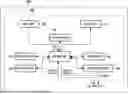
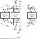


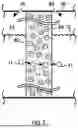
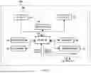
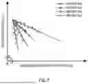
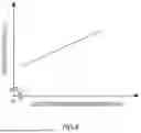


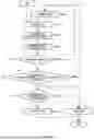


Sources:
- United States Patent and Trademark Office - verify current appl. status at the USPTO↗
Similar patent applications:
- » 20220318029
Operation support apparatus, system, method, and non-transitory computer readable medium storing program - » 20210215497
CONTROL APPARATUS, SYSTEM, NON-TRANSITORY COMPUTER-READABLE MEDIUM, TERMINAL APPARATUS, AND VEHICLE OPERATION SUPPORT METHOD - » 20110093310
COMPUTER-READABLE, NON-TRANSITORY MEDIUM STORING A SYSTEM OPERATIONS MANAGEMENT SUPPORTING PROGRAM, SYSTEM OPERATIONS MANAGEMENT SUPPORTING METHOD, AND SYSTEM OPERATIONS MANAGEMENT SUPPORTING APPARATUS - » 20220027106
Non-transitory computer-readable recording medium having a supporting program, information processing apparatus with an operating system having a general-use printing program and printing method
Recent applications in this class:
- » 20260043160 2026-02-12
CONTROL DEVICE FOR HYDROGEN PRODUCTION FACILITY, HYDROGEN PRODUCTION FACILITY, METHOD FOR CONTROLLING HYDROGEN PRODUCTION FACILITY, AND CONTROL PROGRAM FOR HYDROGEN PRODUCTION FACILITY - » 20260022483 2026-01-22
BACKFLOW SUPPRESSION SYSTEM - » 20260022482 2026-01-22
A SYSTEM AND A METHOD FOR ESTIMATING CURRENT EFFICIENCY OF AN ELECTROLYSER - » 20250369138 2025-12-04
OPERATING AN ELECTROLYSIS CELL - » 20250369137 2025-12-04
OXYGEN GENERATION SYSTEMS FOR LOW GRAVITY APPLICATIONS - » 20250361635 2025-11-27
CONTROL DEVICE FOR ELECTROLYSIS SYSTEM AND ELECTROLYSIS SYSTEM - » 20250347017 2025-11-13
APPARATUS AND METHOD - » 20250341011 2025-11-06
APPARATUS AND METHOD - » 20250297389 2025-09-25
ELECTROLYSIS DEVICE AND ELECTROLYSIS METHOD - » 20250198028 2025-06-19
ELECTROLYZER SYSTEM AND METHOD OF OPERATING SAME WITH INTERMITTENT POWER SOURCES