HEAT EXCHANGER
US20260043618A1
2026-02-12
19/291,534
2025-08-05
Smart Summary: A heat exchanger allows for easy adjustment of where fluids enter and exit without needing different types of plates. It consists of several plates stacked together to create channels for two different fluids. The design includes a case that holds these plates and has an opening on one side. There are holes in a base plate for one of the fluids, while the other fluid can enter or exit through openings in the side or top of the case. This setup makes it more flexible and efficient for transferring heat between the fluids. 🚀 TL;DR
Abstract:
A heat exchanger that can easily change the position of the inlet and outlet of the fluid without increasing the types of plates is disclosed. The heat exchanger includes a laminate including a plurality of plates are laminated to alternately form a channel for a first fluid and a channel for a second fluid in a laminate direction. A case containing the laminate and opening on one side of the laminate direction is provided. A base plate is provided with holes for the second fluid provided on an open side of the case. The case has a side wall extending along the laminate direction. A top surface part is provided on an other side of the laminate direction in the case. An inlet and an outlet for the first fluid to pass through is provided in the side wall or top surface part.
Applicant:
Interested in similar patents?
Get notified when new applications in this technology area are published.
Classification:
F28D9/005 » CPC main
Heat-exchange apparatus having stationary plate-like or laminated conduit assemblies for both heat-exchange media, the media being in contact with different sides of a conduit wall the conduits for one heat-exchange medium being formed by paired plates touching each other the plates having openings therein for circulation of at least one heat-exchange medium from one conduit to another the plates having openings therein for both heat-exchange media
F28F3/086 » CPC further
Plate-like or laminated elements; Assemblies of plate-like or laminated elements; Elements constructed for building-up into stacks, e.g. capable of being taken apart for cleaning having one or more openings therein forming tubular heat-exchange passages
F28D9/00 IPC
Heat-exchange apparatus having stationary plate-like or laminated conduit assemblies for both heat-exchange media, the media being in contact with different sides of a conduit wall
F28F3/08 IPC
Plate-like or laminated elements; Assemblies of plate-like or laminated elements Elements constructed for building-up into stacks, e.g. capable of being taken apart for cleaning
Description
CROSS REFERENCE TO RELATED APPLICATIONS
This application claims priority to and the benefit of Japanese Patent Application No. 2024-129722 filed on Aug. 6, 2024, the contents of which are hereby incorporated by reference in its entirety.
TECHNICAL FIELD
The present invention relates to a heat exchanger.
BACKGROUND
Heat exchangers that perform heat exchange between a plurality of fluids may use a long-life coolant (LLC) or the like as the water-cooled oil cooler to cool the lubricant oil of an internal combustion engine. Among heat exchangers, it is known that there are some heat exchangers that have a casing and a core contained within the space of this casing, with a fluid inlet and a fluid outlet on a side of the peripheral wall that is provided on the side surface of the casing, and with oil inlets and outlets provided in the lamination direction (see, for example, Patent literature 1).
(Patent Literature 1) JP 2011-127819 Publication (Overview of the Invention).
SUMMARY
Incidentally, in the case of conventional heat exchangers such as those shown in Patent Literature 1, when attempting to change the position of the oil inlet and outlet according to various requirements such as the layout of the vehicle, it was necessary to design the shape of the core according to the position of the oil inlet and outlet.
In addition, many heat exchangers constructed by laminating square-shaped plates are formed in the four corners of the plate in diagonal directions with oil in/out ports and cooling water in /out ports, but in such a configuration, the entire heat exchanger was easily rotated in a planar direction and the heat exchanger was arranged to match different oil hole positions, so that the assembly layout could be accommodated without new designing plates with different hole positions. In contrast, heat exchangers constructed by stacking rectangular plates could not be easily rotationally arranged due to layout constraints.
Therefore, there is a need for a configuration in the heat exchanger that allows the position of the oil inlet and outlet to be easily changed without increasing the types of plates.
Accordingly, the present invention is intended to provide a heat exchanger that is made in view of the above-mentioned problems and that can easily change the position of the inlet and outlet of the fluid without increasing the type of plate.
In order to solve the above problems, the heat exchanger according to the present invention has a laminate wherein the plurality of plates are laminated to alternately form a channel for the first fluid and a channel for the second fluid in the laminated direction, a case containing the laminate and opening one side of the laminate direction, a base plate formed with holes for the second fluid passage provided on an open side of the case, the case having a side wall covering the side of the laminate, a top surface part on the other side of the laminate direction in the case, and an inlet and outlet for the first fluid to pass through provided in the side wall or top surface part, the plurality of plates each having peripheral flange parts protruding in the laminate direction from the outer edge, and bosses formed in a pair of corners and having a through hole and protruding toward the channel for the first fluid formed between the plurality of plates, wherein a first distribution channel is formed between the peripheral part of the laminate and the inner surface of the side wall of the case, wherein the first fluid flows along the laminate direction and connects with the channel for the first fluid formed between the plates, which are connected to the second fluid passage hole of the base plate, and also connected to the bosses and through holes of adjacent plates in the laminate direction to allow the second fluid to pass through in the laminate direction, and wherein a second distribution channel is formed to connect with the channel for the second fluid formed between the plurality of plates; of the plurality of plates, the uppermost plate in the laminate direction protrudes toward the laminate direction and is formed so that the height of the peripheral flange parts portion is lower than the height of the peripheral flange parts portions in the other plates and is equivalent to the height of the boss; the lowest plate of the plurality of plates in the laminate direction has a boss with a through hole at the location of the hole for the second fluid passage in the base plate protruding toward the laminate direction and connected to the boss of the adjacent plate in the laminate direction in a liquid-tight manner, in which the top surface part is connected in a liquid tight manner to the boss of the uppermost plate in the laminate direction of the laminate to close the uppermost surface of the second distribution channel.
In a heat exchanger according to one aspect of the present invention, said laminate, except for said lowermost plate, is assembled inverting in the opposite direction to said lamination direction.
In a heat exchanger according to one aspect of the present invention, the plurality of plates are rectangular.
In a heat exchanger according to one aspect of the present invention, the laminate is configured with either a position in which the tip of the peripheral flange parts of the plurality of plates faces upward in the lamination direction or downward in the lamination direction.
In accordance with the present invention, of the plurality of plates, since the stack can be assembled inverted in the opposite direction to the lamination direction except for the lowest plate in the lamination direction, a heat exchanger can be provided that can easily change the position of the inlet and outlet of the fluid without increasing the types of plates.
BRIEF DESCRIPTION OF THE DRAWINGS
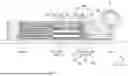
FIG. 1 is a perspective view showing the heat exchanger according to an example of embodiment of the present invention.
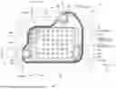
FIG. 2 is a perspective view showing the laminate and base plate of the heat exchanger according to an example of embodiment of the present invention.
FIG. 3 is an exploded perspective view showing the laminate and base plate of the heat exchanger according to an example of embodiment of the present invention.
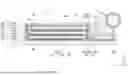
FIG. 4 is a planar view showing the heat exchanger according to an example of embodiment of the present invention.
FIG. 5 is an A-A cross-sectional view of FIG. 4 of the heat exchanger according to the example of embodiment.
FIG. 6 is a B-B cross-sectional view of FIG. 4 of the heat exchanger according to the example of embodiment.
FIG. 7 is a planar view showing a modified example of the heat exchanger according to an example of embodiment of the present invention.
FIG. 8 is an A-A cross-sectional view of FIG. 7 of the heat exchanger according to the example of embodiment.
FIG. 9 is a B-B cross-sectional view of FIG. 7 of the heat exchanger according to the example of embodiment.
DETAILED DESCRIPTION
The examples of embodiment of the present invention will be described below with reference to the drawings.
FIG. 1 is a perspective view showing heat exchanger 1 according to an example of embodiment of the present invention. FIG. 2 is a perspective view showing laminate 2 and base plate 4 of heat exchanger 1. FIG. 3 is an exploded perspective view showing laminate 2 and base plate 4 of heat exchanger 1. FIG. 4 is a planar view illustrating heat exchanger 1.
First, an outline of the representative examples of embodiment of the present invention as disclosed in this application shall be discussed. In the following description, by way of example, the reference numerals on the drawings corresponding to the components of the present invention are noted in parentheses.
[1] The heat exchanger (1) has a laminate (2) wherein the plurality of plates (21, 22, 23, 24) are laminated to alternately form a channel for the first fluid and a channel for the second fluid in the laminated direction, a case (3) containing the laminate and opening one side of the laminate direction, a base plate (4) formed with holes for the second fluid passage provided on an open side of the case, the case having a side wall (32) covering the side of the laminate, a top surface part (31) on the other side of the laminate direction in the case, and an inlet (33) and outlet (34) for the first fluid to pass through provided in the side wall or top surface part, the plate having peripheral flange parts (214, 224, 234, 244) protruding in the laminate direction from the outer edge, and bosses (211, 221, 231, 241) formed in a pair of corners (201, 202) and having a through hole and protruding toward the channel for the first fluid formed between the plurality of plates, and protruding parts (213, 223, 233, 243) protruding in the laminated direction, wherein a first distribution channel (28) is formed between the peripheral part of the laminate and the inner surface of the side wall of the case, wherein the first fluid flows along the laminate direction and connects with the channel for the first fluid formed between the plates, which are connected to the second fluid passage hole of the base plate, and also connected to the bosses and through holes of adjacent plates in the laminate direction to allow the second fluid to pass through in the laminate direction, and wherein a second distribution channel is formed to connect with the channel for the second fluid formed between the plurality of plates; of the plurality of plates, the uppermost plate in the laminate direction protrudes toward the laminate direction and is formed so that the height of the peripheral flange parts portion is lower than the height of the peripheral flange parts portions in the other plates and is equivalent to the height of the boss; the lowest plate of the plurality of plates in the laminate direction has a boss with a through hole at the location of the hole for the second fluid passage in the base plate protruding toward the laminate direction and connected to the boss of the adjacent plate in the laminate direction in a liquid-tight manner, in which the top surface part is connected in a liquid tight manner to the boss (241) of the uppermost plate (24) in the laminate direction of the laminate to close the uppermost surface of the second distribution channel.
[2] The laminate, except for the lowermost plate, is assembled in reverse of the lamination direction.
[3] The plate is rectangular.
[4] The laminate is configured with a choice of either a position in which the tip of the peripheral flange parts of the plate faces upward in the lamination direction or downward in the lamination direction.
Heat exchanger 1 according to the present example of embodiment will be described in detail below. For the convenience of the description below, in heat exchanger 1 as shown in FIG. 1 or the like, the lamination direction of laminate 2 is set to the Z direction (vertical direction, height direction). The Z direction is the thickness direction of case 3 (the direction in which case 3 has an opening as will be described below). The direction perpendicular to the Z direction, or in other words, the long side direction, which is one of the face directions of laminate 2, is the X direction (horizontal direction, width direction), while the short side direction, which is the other of the direction perpendicular to the Z direction, is the Y direction (front-back direction, depth direction). In the following explanation, when describing the positional relationship or direction of each of the constituents as the right side, left side, front side, back side, top side, or bottom side, this refers only to the positional relationship or direction in the drawing, and does not in any way restrict the positional relationship or direction in the actual heat exchanger 1. More specifically, the side of the opening of case 3 in the Z direction (the side on which base plate 4 is provided, the bottom side in FIG. 1 through FIG. 4) shall be referred to as the bottom side, and the opposite side (the top side in FIG. 1 through FIG. 4) shall be referred to as the top side, with each of these referred to simply as the top and bottom. However, the reference to the top and bottom in the Z direction is merely for convenience, and this does not necessarily need to match with the top and bottom in the vertical direction in the actual state of use.
Heat exchanger 1 is used, for example, in a cooling water system of an automobile (vehicle). The automobile to which heat exchanger 1 is provided may have only an internal combustion engine as the driving source, it may have an internal combustion engine and an electric motor, or
it may have only an electric motor, and heat exchanger 1 is provided in order to cool the fluids that is used in these vehicles. Cooling water is an example of the fluid that is used for cooling, and oils such as hydraulic oil are examples of the fluids to be cooled, but these fluids is selected as appropriate according to the driving method of the automobile, the type of heating part, and the required cooling performance, etc. Further, according to the present embodiment, the fluid used for cooling is treated as the first fluid, while the fluid to be cooled is treated as the second fluid, but the fluid used for cooling is treated as the second fluid and the fluid to be cooled is treated as the first fluid.
Heat exchanger 1 is provided with laminate 2, case 3, base plate 4, inlet pipe 5 corresponding to the fluid inlet, and outlet pipe 6 corresponding to the fluid outlet (see FIGS. 1 through 3). Laminated body 2 has a shape that is symmetrical on both the inlet side and the outlet side, with two rotational symmetries in the planar view in relation to the rotational axis that extends in the Z direction along with passage through the intersection points of both diagonal lines L1 and L2, which will be discussed later (see FIG. 4). In other words, when heat exchanger 1 is rotated 180°around this rotational axis, the shape prior to rotation will match the shape after rotation.
In laminate 2, as shown in FIG. 2 through FIG. 4, first plate 21 and second plate 22 are alternately stacked in the Z direction in order to alternately constitute the channel for the first fluid (cooling water channel) and the channel for the second fluid (oil channel) in the Z direction, and at the same time, laminate 2 further has lowermost plate 23 and uppermost plate 24. Laminated body 2 is formed in an abbreviated rectangular parallelepiped shape as a whole as a result of the lamination of each plate 21 to 24 in the Z direction and also extending along the XY direction (wherein the direction along the XY plane is the in-plane direction). The two virtual diagonal lines as seen from the Z direction of laminate 2 shall be treated as first diagonal line L1 and second diagonal line L2, while the pair of corners that is connected by first diagonal line L1 shall be treated as first corner part 201, and the pair of corners that is connected by second diagonal line L2 shall be treated as second corner part 202 (see FIG. 4).
In laminate 2, second plate 22 is overlaid on the top of lowermost plate 23 (or in other words, on the opposite side to base plate 4), and first plate 21 is overlaid thereon. Uppermost plate 24 is overlaid on the top of second plate 22, with a planar shape that is the same as that of first plate 21. Fin plate 25 is provided above second plate 22 and below first plate 21 or uppermost plate 24 in order to form the channel for the second fluid (oil). In contrast, the channel for the first fluid (cooling water) is formed in the space above first plate 21 and lowermost plate 23 and below second plate 22, and in the space above uppermost plate 24 and the surface on the inner side of top surface part 31 of case 3. For each plate comprising laminate 2, it is acceptable to use an aluminum clad material or the like.
As shown in FIG. 3 and FIG. 4, first plate 21 has boss 211 formed as a convex shape on the top side in second corner part 202, through hole 212 formed in boss 211, a plurality of protruding parts 213 with a convex shape formed on the top side on the upper surface, peripheral flange part 214 that protrudes upwards in the Z direction from the peripheral edge, and first blocked part 215 (see FIG. 3) that faces downwards in first corner part 201 and of which the edge part extends in the X-Y direction. Of the corner parts of the rectangle of first plate 21, part of peripheral flange part 214 in first corner part 201 is cut off, and first blocked part 215 is formed in that position.
As shown in FIG. 3 and FIG. 4, second plate 22 has boss 221 formed as a convex shape on the bottom side in second corner part 202, through hole 222 formed in boss 221, a plurality of protruding parts 223 with a convex shape formed on the bottom side on the bottom surface, peripheral flange part 224 that protrudes upwards in the Z direction from the peripheral edge, and second blocked part 225 (see FIG. 3) that faces upwards in first corner part 201 and of which the edge part extends in the X-Y direction. Of the corner parts of the rectangle of second plate 22, part of peripheral flange part 224 in first corner part 201 is cut off, and second blocked part 225 is formed in that position.
As shown in FIG. 3 and FIG. 4, as is the case with first plate 21, uppermost plate 24 has boss 241 formed in second corner part 202, a plurality of protruding parts 243, peripheral flange part 244, and first blocked part 245, with a shape in which part of the rectangle has been cut off.
Although it is also acceptable to have a configuration in which no through hole is formed in boss 241, through hole 242 is formed in the present example of embodiment. Uppermost plate 24 differs from first plate 21 in that the height of peripheral flange part 244 is lower than the height of peripheral flange part 224 of first plate 21, and is approximately the same as the height of boss 241.
Lowermost plate 23 has a different shape than the other plates, as shown in FIG. 3 and FIG. 4. More specifically, lowermost plate 23 is formed in a shape of which the peripheral part follows the shape of the peripheral part of bottom end of side wall 32 of case 3. Lowermost plate 23 has first projecting part 235 and second projecting part 236 (see FIG. 4) that protrude in the X-Y direction on the peripheral side in the positions that correspond to first blocked part 215 and 245 and second blocked part 225 of the other plates. Also, lowermost plate 23 is provided with rib 237 (see FIG. 3) in two locations further inside than the part that extends in the long side among the positions that correspond to peripheral flange parts 214 and 224 of the other plates. In addition to boss 231 with a convex shape on the top side formed in second corner part 202, lowermost plate 23 has through hole 232 formed in boss 231, a plurality of protruding parts 233 formed on the top surface, and peripheral flange part 234 that protrudes to the top side in the Z direction from the peripheral part.
Peripheral flange parts 214, 224, and 244 are formed in the parts of the peripheral part of each plate excluding the parts that correspond to first blocked parts 215 and 245 and second blocked part 225, as is seen in the planar view in FIG. 4, and have a taper part with an incline in relation to the Z direction such that they face the outside as they face the top side, which is the projection side (or in other words, such that the area that is enclosed by the peripheral flange part will increase). As a result, for first plate 21, second plate 22, and uppermost plate 24, it will be possible to fit together the tapers of each peripheral flange part that are adjacent in the Z direction for brazing such that the peripheral flange part of the plate on the bottom side will be positioned to the outside of the peripheral flange part of the adjacent plate on the top side. Peripheral flange part 214 of first plate 21 is positioned to the outside of peripheral flange part 224 of second plate 22 that is adjacent on the top side, while peripheral flange part 224 of second plate 22 is positioned to the outside of peripheral flange part 214 of first plate 21 that is adjacent on the top side. Below the bottom surface on the inner peripheral side of peripheral flange part 224 in second plate 22, which is at the bottommost side, there is rib 237 that is provided on lowermost plate 23 on the bottom side of this second plate 22, and the bottom surface of second plate 22 that is at the bottommost side is brazed together with rib 237 that is adjacent in the Z direction.
It will be possible to assemble a plurality of plates by fitting together the taper of these types of peripheral flange parts 214, 224, and 244 for brazing. For the assembled form of first plate 21, second plate 22, and uppermost plate 24, rib 237 is brazed together with the bottom surface near peripheral flange part 224 of second plate 22, which is at the bottommost side on top of lowermost plate 23 (see FIG. 5 and FIG. 6), forming laminate 2 with a rectangular parallelepiped shape overall, as shown in FIG. 2. Peripheral flange part 234 of lowermost plate 23 is formed to follow the shape of the inner surface at the bottom edge of side wall 32 of case 3, and the housing is formed by performing liquid-tight brazing of lowermost plate 23 and case 3. Laminated body 2 is assembled by laminating plates within case 3, or it is also acceptable to perform assembly outside of case 3 for housing within case 3 later.
Among peripheral flange parts 214, 224, and 244, the parts that extend along the Y direction as shown in FIG. 2 constitute fluid guide walls 210, 220, and 240. The first fluid and second fluid will flow in the direction of diagonal lines L1 and L2, and as a result, it will be possible to ensure that the first fluid and second fluid will flow along the inner surface of fluid guide walls 210, 220, 230 and 240.
Following assembly, by overlapping first blocked parts 215 and 245 and second blocked part 225 in laminate 2, depression 26 that is concave in the central direction of the Y direction of the side wall will be formed near first corner part 201 of peripheral part 20 of laminate 2. In depression 26, a gap is formed between case 3 and laminate 2, and between the outer surface of peripheral part 20 and the inner surface of side wall 32, and this gap forms first distribution channel 28 through which the first fluid can pass along the Z direction.
Boss 211 is formed in first plate 21 to extend towards the top side in the area surrounding through hole 212, while boss 221 is formed in second plate 22 to extend towards the bottom side in the area surrounding through hole 222. Boss 241 that extends towards the top side in the area surrounding through hole 242 is formed in uppermost plate 24 in the position that corresponds to boss 211 and boss 221 of the other plates. These bosses are joined together in laminate 2. Following assembly, in laminate 2, bosses 211, 221, and 231 overlap each other, while through holes 212, 222, and 232 are connected with each other, resulting in the formation of second distribution channel 27 through which the second fluid can pass along the Z direction. Boss 241 of uppermost plate 24 is brazed with the inner surface side of top surface part 31 of case 3 such that through hole 242 of boss 241 will be blocked. In the present example of embodiment, through hole 242 is formed in boss 241 of uppermost plate 24, but it is also acceptable to omit the formation of through hole 242. Also, the space between the top side of first plate 21 and the bottom side of second plate 22 will be divided from second distribution channel 27, ensuring that the second fluid that passes through second distribution channel 27 will not flow into this space. In contrast, the space between the bottom side of first plate 21 and the top side of second plate 22 is connected to second distribution channel 27.
As a result of the formation of peripheral flange parts 214, 224, and 244 and rib 237 in laminate 2, there is a division between the space between plates and the external space (the space within case 3) excluding depression 26. As a result of the joining of first blocked part 215 and second blocked part 225 in depression 26, a division between the space between the bottom side of first plate 21 and the top side of second plate 22 and the external space is created, while the space between the top side of first plate 21 and the bottom side of second plate 22 is connected to the external space.
Heat exchanger 1 is provided with case 3 that has a flat, approximately rectangular parallelepiped shape. As shown in FIGS. 1 and 4, case 3 is formed to have a bottomed cylindrical shape with top surface part 31, cylindrical side wall 32 that is contiguous with the peripheral part of top surface part 31, sloped surface parts 35 and 36 that are contiguous to side wall 32 and top surface part 31 and are provided at an incline in relation to side wall 32, and inlet 33 and outlet 34 that are provided in sloped surface parts 35 and 36 and through which the first fluid passes.
In case 3 as well, the corners are connected by first diagonal line L1 and second diagonal line L2 as described above. In case 3, the pair of corners that is connected by first diagonal line L1 is set as first corner part 301, while the pair of corners that is connected by second diagonal line L2 is set as second corner part 302.
Top surface part 31 is formed in a tabular shape along the XY plane. Top surface part 31 is formed such that the planar shape covers the rectangular laminate 2 from the top surface side while also covering the top surface side of sloped surface parts 35 and 36.
Side wall part 32 has a pair of long-side side walls 321 that correspond to the long side of top surface part 31, a pair of short-side side walls 322 that correspond to the short side, and a total of four curved surface parts 323 that are positioned in the space between long-side side wall 321 and short-side side wall 322. Side wall part 32 extends along the Z direction and X direction or Y direction. Long-side side wall 321 extends along the Z direction and Y direction. Short-side side wall 322 extends along the Z direction and X direction.
The side wall 32 has an enlarged part 324, in which the internal dimensions and external dimensions are enlarged, at the edge part on the downward side, which is the open side of case 3. The lowermost plate 23 has larger external dimensions than the other plates, and the enlarged part 324 is provided for installing the lowermost plate 23.
Sloped surface parts 35 and 36 are provided in first corner 301, which is the position that corresponds to depression 26 of laminate 2 among the corners of case 3. Sloped surface parts 35 and 36 have a surface that is inclined from top surface part 31 on the top side in the Z direction towards base plate 4 and lowermost plate 23 on the bottom side, and towards the periphery side of base plate 4 in the X-Y plane direction. In other words, sloped surface parts 35 and 36 are provided at an angle with respect to at least the Z direction among the directions in which side wall 32 extends. For this reason, sloped surface parts 35 and 36 are provided such that they face the top side. Sloped surface part 35 is provided in a plurality of directions with respect to side wall 32, or in other words, it is provided in the Z direction, as well as in the X direction and Y direction. In other words, sloped surface part 35 is provided at an angle facing the right side in the Y direction and the top side in the X direction in FIG. 1 and FIG. 4. Sloped surface part 36 is provided at an incline in the Z and Y directions. In other words, sloped surface part 36 is provided to face the right side in the Y direction in FIGS. 1 and 4. The angle of inclination and the orientation of the inclination of sloped surface parts 35 and 36 are not limited to those shown in the present example of embodiment.
In sloped surface parts 35 and 36, inlet 33 and outlet 34, through which the first fluid may pass, are formed. Inlet 33 and outlet 34 are formed in sloped surface parts 35 and 36, for example, in the center.
Inlet pipe 5 and outlet pipe 6 are cylindrical members through which the first fluid may pass, and are each connected to inlet 33 and outlet 34, respectively, in a liquid-tight manner. Because inlet 33 and outlet 34 are provided in sloped surface part 35 and sloped surface part 36 of the oblique side, the length dimensions of sloped surface part 35 and sloped surface part 36 are greater than the height dimensions of side wall 32, making it possible to attach inlet pipe 5 and outlet pipe 6 with a pipe diameter that is larger than the height dimensions of case 3 (see FIGS. 1 and 4).
Base plate 4 is formed in a tabular shape. A pair of through holes 41 to enable the passage of the second fluid and a plurality of mounting holes 42 for use in attachment to another device is formed in base plate 4. In the state in which laminate 2 is housed in case 3 and base plate 4 is attached to case 3, through hole 41 and second distribution channel 27 will be connected (see FIG. 5). In the present example of embodiment, the channel for the second fluid and through hole 41 are connected directly in another device, but it is also acceptable to enable the introduction and outflow of fluid by attaching a pipe or the like to base plate 4.
FIG. 5 is an A-A cross-sectional view of heat exchanger 1 (see FIG. 4). FIG. 6 is a B-B cross-sectional view of heat exchanger 1 (see FIG. 4).
As shown in FIGS. 5 and 6, in heat exchanger 1, laminate 2 is in contact with the inner surface of top surface part 31 and base plate 4 of case 3 in the lamination direction. More specifically, the edges on the top side of the lamination direction of each of boss 241 and protruding part 243, which are provided in uppermost plate 24 of laminate 2, are in contact with the inner wall that is the surface on the inner side of top surface part 31 of case 3, while the top edge of peripheral flange part 244 is either in contact with the inner wall of top surface part 31 or is positioned with a slight gap between it and the inner wall of top surface part 31. In other words, the heights of peripheral flange part 244, boss 241, and protruding part 243 that are provided on the top side (one end of the lamination direction) in the lamination direction of laminate 2, match or generally match, or in other words, are equivalent heights.
In heat exchanger 1, the planar part of lowermost plate 23 that is provided on the bottom side in the lamination direction, which is the other end of the lamination direction of laminate 2, is in contact with the surface of the top side in the lamination direction, which is the surface on the inner side of base plate 4 (see FIG. 3 and FIG. 5).
FIG. 7 is a planar view showing heat exchanger 1B of a variant pertaining to the example of embodiment. FIG. 8 is an A-A cross-sectional view of FIG. 7 of heat exchanger 1B. FIG. 9 is a B-B cross-sectional view of FIG. 7 of heat exchanger 1B.
As shown in FIGS. 7 to 9, heat exchanger 1B of the variant differs in the form of the lamination of the plurality of plates in laminate 2B. More specifically, laminate 2B in heat exchanger 1B has the structure of laminate 2 of heat exchanger 1 as described above, wherein the parts excluding lowermost plate 23 are attached upside down, and lowermost plate 23B has a shape that corresponds to the position of a different through hole 41. Base plate 4B has a different position of through hole 41B in relation to through hole 41 of base plate 4, allowing it to correspond to a different oil port position on the vehicle side. Case 3B is formed so as to be symmetrical in the X-Y plane view with respect to case 3, and lowermost plate 23B is formed with boss 231B and through hole 232B, with an outer peripheral shape that matches base plate 4B and case 3B. The plates that are laminated on lowermost plate 23B are identical in configuration to uppermost plate 24 in laminate 2. In laminate 2B, this plate is described as lower plate 29 in order to distinguish it from uppermost plate 24 of laminate 2. Because lower plate 29 is the same as uppermost plate 24 of laminate 2, lowermost plate 29 differs from first plate 21 in terms of the fact that the height of peripheral flange part 244 is lower than the height of peripheral flange part 224 of first plate 21, so the height is approximately the same as the height of boss 241. As is the case with uppermost plate 24, lower plate 29 has boss 291, through hole 292, protruding part 293, and peripheral flange part 294 that constitutes fluid guide wall 290.
Laminated body 2B is laminated such that peripheral flange parts 214, 224, and 294 face downward. To rephrase, laminate 2B of heat exchanger 1B has a form in which laminate 2B is housed inside case 3 by inverting the parts excluding lowermost plate 23 of heat exchanger 1 against laminate 2 of heat exchanger 1 in the vertical direction, and placing [laminate 2B] on top of lowermost plate 23B, which is formed such that it will have a line-symmetrical shape having the long side of lowermost plate 23 when viewing the XY plane as the reference.
By configuring laminate 2B as described above, the position of first distribution channel 28 that is formed by depression 26 and the position of second distribution channel 27 that connects through holes 212, 222, 232B, and 292 to enable the second fluid to pass through in the Z direction will be different positions from those in laminate 2 of heat exchanger 1 as described above. More specifically, the position of first distribution channel 28 in heat exchanger 1B is in second corner part 302 on second diagonal line L2, while first distribution channel 28 in heat exchanger 1 is positioned in first corner part 301 on first diagonal line L1. Also, the position of second distribution channel 27 in heat exchanger 1B is in first corner part 301 on first diagonal line L1, while second distribution channel 27 in heat exchanger 1 is positioned in second corner part 302 on second diagonal line L2.
The reason why the positions of first distribution channel 28 and second distribution channel 27 differ from those in heat exchanger 1 is because in heat exchanger 1B, the positions are aligned to the position of through hole 41B, which is located at a different position in base plate 4B or in other words, because the positions are aligned to different fluid ports on the vehicle side. Because of the differences in the position of first distribution channel 28 and second distribution channel 27, in heat exchanger 1B, the position of boss 231B and through hole 232B for connecting second distribution channel 27 with through hole 41B in lowermost plate 23B differs from the position of boss 231 and through hole 232 in lowermost plate 23 of heat exchanger 1.
Here, regarding the terms “lamination direction” and “top/bottom” as used in FIG. 8 and FIG. 9, in the following explanation, the lamination direction will be treated as the direction of the overlap of plates from the lower side of the figure to the upper side of the figure as was the case in heat exchanger 1 and laminate 2, and the part on the upper side of the figure will be treated as the top, while the part on the lower side will be treated as the bottom.
In laminate 2B, the uppermost plate is second plate 22, unlike uppermost plate 24 in laminate 2. More specifically, in laminate 2, the height of peripheral flange part 244 in first plate 21 is lower than the height of peripheral flange part 244 of first plate 21, so that uppermost plate 24 will have approximately the same height as boss 241, while the uppermost plate in laminate 2B has the same structure as second plate 22 of laminate 2. Lowermost plate 23B is formed such that lowermost plate 23 of laminate 2 will have a line-symmetrical shape with the long-side as viewed on the XY plane as reference, as was described above. Lower plate 29, which is the plate at the very bottom of laminate 2B excluding lowermost plate 23B, has the same structure as uppermost plate 24 of laminate 2, as was described above.
As shown in FIGS. 8 and 9, in heat exchanger 1B, laminate 2B is in contact with the inner surface of top surface part 31 and base plate 4 in the lamination direction, the same as in laminate 2 that was described already. More specifically, the edges of each of boss 221 and protruding part 223 that are provided on second plate 22, which is the uppermost plate of laminate 2B, on the upper side in the lamination direction may brought into contact with and mutually brazed to the inner wall, that is the surface on the inner side of top surface part 31 of case 3. In other words, in laminate 2B, the heights of boss 221 and protruding part 223 that is provided on the upper side in the lamination direction that is the side of one edge of the lamination direction are the same or approximately the same. For this reason, by brazing boss 221 and the surface on the inner side of top surface part 31 of case 3, it will be possible to block through hole 222 on the inner side of boss 221, and to block the top edge of second distribution channel 27. Therefore, in heat exchanger 1B, it will be possible to deal with the difference in the position of through hole 41B of base plate 4B by inverting the constituent materials of laminate 2B excluding lowermost plate 23B.
In heat exchanger 1B, the planar part of lowermost plate 23B that is provided on the lower side in the lamination direction, which is the other end of the lamination direction of laminate 2B, is in contact with the surface of the upper side in the lamination direction, which is the surface on the inner side of base plate 4B.
Operation of the Heat Exchanger
Next, the operation of heat exchangers 1 and 1B as described above will be discussed.
In heat exchangers 1 and 1B as described above, for example, by performing heating while laminate 2 or 2B is housed within case 3 or 3B, the brazing filler metal that has been provided on the surface of each part of laminate 2 or 2B will melt, and by performing cooling, the brazing filler metal will solidify, joining each part. More specifically, the peripheral flange parts of adjacent plates will be joined together, while at the same time, the tip of the protruding part of the plates will be joined with the bottom surface and top surface of the plates.
Next, the relationship between each part of cases 3 and 3B and laminated bodies 2 and 2B, as well as the flow of fluid, will be discussed. The external dimensions of laminated bodies 2 and 2B, which have a rectangular parallelepiped shape, are mostly the same or slightly smaller than the internal dimensions of side wall 32, which is a rectangular cylinder. In other words, of laminated bodies 2 and 2B, for the parts excluding lowermost plates 23 and 23B, the peripheral part 20 follows the inner surface of side wall 32 excluding the area around depression 26, first projecting part 235, and second projecting part 236. In addition, inlet 33 and outlet 34 are provided near first corner part 301 or second corner part 302, while depression 26 is provided near first corner part 201 or second corner part 202. In the space between depression 26 and side wall 32, there is a space to connect inlet 33 and outlet 34.
In this way, a gap is formed between case 3 or 3B and laminate 2 or 2B in depression 26 between the outer surface of peripheral part 20 and the inner surface of side wall 32, and this gap forms first distribution channel 28. Also, for laminated bodies 2 and 2B, first distribution channel 28 is connected to the space between the upper side of first plate 21 and the lower side of first plate 22 in laminate 2, and to the space between the lower side of first plate 21 and the upper side of second plate 22 in laminate 2B.
The first fluid is introduced from inlet pipe 5 into case 3 and drawn outwards from outlet pipe 6. The first fluid that was introduced into inlet 33 by inlet pipe 5 will reach first distribution channel 28. In first distribution channel 28, not only will it be possible for the first fluid to flow along the Z direction, but it will also be able to flow into the space between the upper side of first plate 21 and the lower side of second plate 22 in laminate 2, or into the space between the lower side of first plate 21 and the upper side of second plate 22 in laminate 2B. In other words, the first fluid will be distributed in the Z direction, and it will flow into the plurality of spaces between the upper side of first plate 21 and the lower side of second plate 22 in laminate 2, and into the space between the lower side of first plate 21 and the upper side of second plate 22 in laminate 2B.
In laminated bodies 2 and 2B, the first fluid reaches from the first distribution channel 28 on the inlet 33 side to the first distribution channel 28 on the outlet 34 side. Then, the first fluid that had flowed into first distribution channel 28 on the outlet 34 side will flow along the Z direction so as to be directed towards outlet 34 from each of the spaces between the upper side of first plate 21 and the lower side of second plate 22 in the case of laminate 2, and from each of the spaces between the lower side of first plate 21 and the upper side of second plate 22 in laminate 2B. In other words, the first fluid that had been distributed will be aggregated once again. The first fluid will then be drawn outwards from outlet 34 by outlet pipe 6.
The second fluid is introduced into and drawn out of laminated bodies 2 and 2B using one of the pair of through holes 41 and 41B as the inlet and using the other as the outlet. The second fluid that was flowed from one of the pair of through holes 41 and 41B into second distribution channel 27 can flow along the Z direction, and can flow into the space between the lower side of first plate 21 and the upper side of second plate 22 in laminate 2, or into the space between the upper side of first plate 21 and the lower side of second plate 22 in laminate 2B. In other words, the second fluid will be distributed in the Z direction, and it will flow into the plurality of spaces between the lower side of first plate 21 and the upper side of second plate 22 in laminate 2, and into the space between the upper side of first plate 21 and the lower side of second plate 22 in laminate 2B.
In laminated bodies 2 and 2B, the second fluid will flow from one of the pair of second distribution channel 27 towards the other. The second fluid that had flowed into the other of second distribution channel 27 will flow along the Z direction so as to be directed towards the other of through holes 41 and 41B from each of the spaces between the lower side of first plate 21 and the upper side of second plate 22 in the case of laminate 2, and from each of the spaces between the upper side of first plate 21 and the lower side of second plate 22 in laminate 2B. In other words, the second fluid that had been distributed will be aggregated once again. The second fluid will then be drawn outside from the other through hole 41 or 41B.
When the first fluid and the second fluid flow as described above, it is preferable for the direction of flows in the X direction to be opposite to each other. In other words, it is preferable for the second fluid to be introduced into case 3 from through hole 41 or 41B that is closer to outlet 34 in the X direction among the pair of through holes 41 and 41B. Depending on conditions such as fluid type and flow rate, it is also acceptable for the first fluid and the second fluid to flow in the same direction in the X direction.
In heat exchangers 1 and 1B, cases 3 and 3B have side walls 32 that cover the side surfaces of laminated bodies 2 and 2B as well as sloped surface parts 35 and 36 that are connected to top surface part 31 that is provided on the upper side, which is the other side in the lamination direction in cases 3 and 3B, and that are provided at an inclination in relation to side wall 32. Sloped surface parts 35 and 36 are provided with inlet 33 and outlet 34 through which the first fluid may pass.
According to heat exchangers 1 and 1B, by providing inlet 33 and outlet 34 in sloped surface parts 35 and 36, the diameter of inlet 33 and outlet 34 can be made to be greater than the length of wall part 32 in the lamination direction without being bound by the dimensions of side wall 32.
In other words, according to heat exchangers 1 and 1B, in response to the demand for a reduction in the size of the dimensions of heat exchangers in the vertical (height) direction and a reduction in pressure losses as a result of factors such as the electrification of vehicles, it will be possible to realize a configuration that can achieve both a reduction in the size of the dimensions in the vertical (height) direction and an increase in the diameter of the inlet and outlet.
Also, heat exchangers 1 and 1B are provided with sloped surface parts 35 and 36 that protrude outwardly from side wall 32. By using this type of configuration, it will be possible to ensure a channel that connects first distribution channel 28 that is formed between peripheral part 20 and the inner surface of side wall 32 with inlet 33 and outlet 34 in heat exchangers 1 and 1B, thereby making it possible to provide inlet 33 and outlet 34 at a variety of positions.
In heat exchangers 1 and 1B, sloped surface parts 35 and 36 are provided at an incline in a plurality of directions relative to side wall 32. In addition, in heat exchangers 1 and 1B, sloped surface parts 35 and 36 are provided facing the side of top surface part 31. By using this type of configuration, it will be possible to realize a design that matches the layout of the vehicle while enabling both a reduction in the size of the dimensions in the vertical (height) direction and an increase in the size of the inlet and outlet in heat exchangers 1 and 1B.
In heat exchangers 1 and 1B, it is also acceptable for laminated bodies 2 and 2B to be in contact with the inner surface of top surface part 31 and base plate 4 in the lamination direction. By using this type of configuration, it will be possible to enable both a reduction in the size of the dimensions in the vertical (height) direction and an increase in the size of the inlet and outlet in heat exchangers 1 and 1B.
In heat exchangers 1 and 1B, plate 24 (29) matches or mostly matches the height of boss 241, protruding part 243, and peripheral flange part 244 in laminated bodies 2 and 2B. Therefore, in heat exchangers 1 and 1B, it is possible to select one of either an arrangement in which the tip part of peripheral flange parts 214, 224, and 244 of the plate faces the upper side in the lamination direction (see FIG. 5 and FIG. 6) as in laminate 2 described above, or an arrangement in which the tip part faces the lower side in the lamination direction (see FIG. 8 and FIG. 9) as in laminate 2B. Therefore, in heat exchangers 1 and 1B, even when an attempt is made to change the positions of through holes 41 and 41B of base plates 4 and 4B that are the oil inlet and outlet according to various types of requirements, such as the layout of the vehicle, it will be possible to use first plate 21, second plate 22, and uppermost plate 24 in common in laminated bodies 2 and 2B, making it possible to minimize the types of plates that must be fashioned anew in relation to layouts having different oil inlet and outlet attachment positions, thereby making it possible to minimize the types of plates.
Various examples/embodiments are described herein for various apparatuses, systems, and/or methods. Numerous specific details are set forth to provide a thorough understanding of the overall structure, function, manufacture, and use of the examples/embodiments as described in the specification and illustrated in the accompanying drawings. It will be understood by those skilled in the art, however, that the examples/embodiments may be practiced without such specific details. In other instances, well-known operations, components, and elements have not been described in detail so as not to obscure the examples/embodiments described in the specification. Those of ordinary skill in the art will understand that the examples/embodiments described and illustrated herein are non-limiting examples, and thus it can be appreciated that the specific structural and functional details disclosed herein may be representative and do not necessarily limit the scope of the embodiments.
Reference throughout the specification to “examples, “in examples,” “with examples,” “various embodiments,” “with embodiments,” “in embodiments,” or “an embodiment,” or the like, means that a particular feature, structure, or characteristic described in connection with the example/embodiment is included in at least one embodiment. Thus, appearances of the phrases “examples, “in examples,” “with examples,” “in various embodiments,” “with embodiments,” “in embodiments,” or “an embodiment,” or the like, in places throughout the specification are not necessarily all referring to the same embodiment. Furthermore, the particular features, structures, or characteristics may be combined in any suitable manner in one or more examples/embodiments. Thus, the particular features, structures, or characteristics illustrated or described in connection with one embodiment/example may be combined, in whole or in part, with the features, structures, functions, and/or characteristics of one or more other embodiments/examples without limitation given that such combination is not illogical or non-functional. Moreover, many modifications may be made to adapt a particular situation or material to the teachings of the present disclosure without departing from the scope thereof.
It should be understood that references to a single element are not necessarily so limited and may include one or more of such element. Any directional references (e.g., plus, minus, upper, lower, upward, downward, left, right, leftward, rightward, top, bottom, above, below, vertical, horizontal, clockwise, and counterclockwise) are only used for identification purposes to aid the reader's understanding of the present disclosure, and do not create limitations, particularly as to the position, orientation, or use of examples/embodiments.
“One or more” includes a function being performed by one element, a function being performed by more than one element, e.g., in a distributed fashion, several functions being performed by one element, several functions being performed by several elements, or any combination of the above.
It will also be understood that, although the terms first, second, etc. are, in some instances, used herein to describe various elements, these elements should not be limited by these terms. These terms are only used to distinguish one element from another. For example, a first element could be termed a second element, and, similarly, a second element could be termed a first element, without departing from the scope of the various described embodiments. The first element and the second element are both elements, but they are not the same element.
The terminology used in the description of the various described embodiments herein is for the purpose of describing particular embodiments only and is not intended to be limiting. As used in the description of the various described embodiments and the appended claims, the singular forms “a”, “an” and “the” are intended to include the plural forms as well, unless the context clearly indicates otherwise. It will also be understood that the phrase “at least one of” followed by successive elements separate by the word “and” (e.g., “at least one of A and B”) is to be interpreted the same as “and/or” and as used herein refers to and encompasses any and all possible combinations of one or more of the associated listed items. It will be further understood that the terms “includes,” “including,” “comprises,” and/or “comprising,” when used in this specification, specify the presence of stated features, integers, steps, operations, elements, and/or components, but do not preclude the presence or addition of one or more other features, integers, steps, operations, elements, components, and/or groups thereof.
Joinder references (e.g., attached, coupled, connected, and the like) are to be construed broadly and may include intermediate members between a connection of elements, relative movement between elements, direct connections, indirect connections, fixed connections, movable connections, operative connections, indirect contact, and/or direct contact. As such, joinder references do not necessarily imply that two elements are directly connected/coupled and in fixed relation to each other. Connections of electrical components, if any, may include mechanical connections, electrical connections, wired connections, and/or wireless connections, among others. Uses of “e.g. ” and “such as” in the specification are to be construed broadly and are used to provide non-limiting examples of embodiments of the disclosure, and the disclosure is not limited to such examples.
While processes, systems, and methods may be described herein in connection with one or more steps in a particular sequence, it should be understood that such methods may be practiced with the steps in a different order, with certain steps performed simultaneously, with additional steps, and/or with certain described steps omitted.
As used herein, the term “if” is, optionally, construed to mean “when” or “upon” or “in response to determining” or “in response to detecting,” depending on the context. Similarly, the phrase “if it is determined” or “if [a stated condition or event] is detected” is, optionally, construed to mean “upon determining” or “in response to determining” or “upon detecting [the stated condition or event]” or “in response to detecting [the stated condition or event],” depending on the context.
All matter contained in the above description or shown in the accompanying drawings shall be interpreted as illustrative only and not limiting. Changes in detail or structure may be made without departing from the present disclosure.
(Explanation of references)
Claims
What is claimed is:1. A heat exchanger comprising:
a laminate where a plurality of plates are laminated to alternately form a channel for a first fluid and a channel for a second fluid in a laminate direction,
a case containing the laminate and opening one side of the laminate direction,
a base plate provided with holes for the second fluid provided on an open side of the case, the case having a side wall extending along the laminate direction,
a top surface part on an other side of the laminate direction in the case,
an inlet and an outlet for the first fluid to pass through provided in the side wall or top surface part,
the plurality of plates each having peripheral flange parts protruding in the laminate direction from an outer edge,
bosses provided in a pair of corners and having a through hole and protruding toward the channel for the first fluid formed between the plurality of plates,
wherein a first distribution channel is formed between a peripheral part of the laminate and an inner surface of the side wall of the case,
wherein the first fluid flows along the laminate direction and connects with the channel for the first fluid formed between the plurality of plates,
the plurality of plates connected to a second fluid passage hole of the base plate, and also connected to the bosses and through holes of adjacent plates in the laminate direction to allow the second fluid to pass through in the laminate direction,
wherein a second distribution channel is formed to connect with the channel for the second fluid formed between the plurality of plates;
an uppermost plate of the plurality of plates in the laminate direction protrudes toward the laminate direction and is formed so that a height of the peripheral flange parts is lower than a height of the peripheral flange parts in the other plates and is equivalent to a height of the boss;
a lowest plate of the plurality of plates in the laminate direction has a boss with a through hole at the location of the hole for the second fluid passage hole in the base plate protruding toward the laminate direction and connected to the boss of the adjacent plate in the laminate direction in a liquid-tight manner,
wherein the top surface part is connected in a liquid tight manner to the boss of the uppermost plate in the laminate direction of the laminate to close the uppermost surface of the second distribution channel.
2. The heat exchanger of claim 1, wherein the laminate, excluding the lowest plate, is assembled inverting in the opposite direction to the lamination direction.
3. The heat exchanger of claim 1, wherein the plurality of plates are rectangular.
4. The heat exchanger of claim 1, wherein the laminate is selectively configured such that a tip of the peripheral flange parts of the plurality of plates is either in a lamination direction upwardly facing or in a lamination direction downwardly facing arrangement.
5. The heat exchanger of claim 2, wherein the laminate is selectively configured such that a tip of the peripheral flange parts of the plurality of plates is either in a lamination direction upwardly facing or in a lamination direction downwardly facing arrangement.
6. The heat exchanger of claim 3, wherein the laminate is selectively configured such that a tip of the peripheral flange parts of the plurality of plates is either in a lamination direction upwardly facing or in a lamination direction downwardly facing arrangement.
7. A heat exchanger comprising:
a laminate including a plurality of plates are laminated to alternately form a channel for a first fluid and a channel for a second fluid in a laminate direction,
a case containing the laminate and opening on one side of the laminate direction,
a base plate provided with holes for the second fluid provided on an open side of the case, the case having a side wall extending along the laminate direction,
a top surface part on an other side of the laminate direction in the case,
an inlet and an outlet for the first fluid to pass through provided in the side wall or top surface part,
the plurality of plates each having peripheral flange parts protruding in the laminate direction from an outer edge,
bosses provided in a pair of corners and having a through hole and protruding toward the channel for the first fluid formed between the plurality of plates,
wherein a first distribution channel is formed between a peripheral part of the laminate and an inner surface of the side wall of the case,
wherein the first fluid flows along the laminate direction and connects with the channel for the first fluid formed between the plurality of plates,
the plurality of plates connected to a second fluid passage hole of the base plate, and also connected to the bosses and through holes of adjacent plates in the laminate direction to allow the second fluid to pass through in the laminate direction,
wherein a second distribution channel is formed to connect with the channel for the second fluid formed between the plurality of plates;
wherein the top surface part is connected in a liquid tight manner to the boss of the uppermost plate in the laminate direction of the laminate to close the uppermost surface of the second distribution channel.
8. The heat exchanger of claim 7, wherein an uppermost plate of the plurality of plates in the laminate direction protrudes toward the laminate direction and is formed so that a height of the peripheral flange parts is lower than a height of the peripheral flange parts in the other plates and is equivalent to a height of the boss.
9. The heat exchanger of claim 7, wherein a lowest plate of the plurality of plates in the laminate direction has a boss with a through hole at the location of the hole for the second fluid passage hole in the base plate protruding toward the laminate direction and connected to the boss of the adjacent plate in the laminate direction in a liquid-tight manner.
10. The heat exchanger of claim 9, wherein the laminate, excluding the lowest plate, is assembled inverting in the opposite direction to the lamination direction.
11. The heat exchanger of claim 7, wherein the plurality of plates are rectangular.
12. The heat exchanger of claim 7, wherein the laminate is selectively configured such that a tip of the peripheral flange parts of the plurality of plates is either in a lamination direction upwardly facing or in a lamination direction downwardly facing arrangement.
Images & Drawings included:


Sources:
- United States Patent and Trademark Office - verify current appl. status at the USPTO↗
Similar patent applications:
- » 20130118720
HEAT EXCHANGING ELEMENT FOR A HEAT EXCHANGER, METHOD OF MANUFACTURING A HEAT EXCHANGING ELEMENT FOR A HEAT EXCHANGER, HEAT EXCHANGER, AND RETROFITTING METHOD FOR A HEAT EXCHANGER - » 20200318855
Heat exchanger pipe, method of manufacturing heat exchanger pipe, heat exchanger fin, elliptical heat exchanger pipe, and hot water storage type heat exchanger having elliptical heat exchanger pipe - » 20180245863
Heat exchanger, heat exchange method using heat exchanger, heat transport system using heat exchanger, and heat transport method using heat transport system - » 20180238634
Heat exchange system with main heat exchange chamber and subsidiary heat exchange chamber and method for exchanging heat by using the heat exchange system - » 20060086486
Heat exchanger, heat exchanger tube member, heat exchanger fin member and process for fabricating the heat exchanger - » 20080105415
Chamber For Holding A Fluid For A Heat Exchanger, Heat Exchanger, More Particularly For A Heat Exchange Unit, And A Heat Exchange Unit, In Particular In The Form Of A Monoblock - » 20060059946
Finned tube for heat exchangers, heat exchanger, apparatus for fabricating heat exchanger finned tube and process for fabricating heat exchanger finned tube - » 10492206
Finned tube for heat exchangers, heat exchanger, process for producing heat exchanger finned tube, and process for fabricating heat exchanger - » 20180238633
Heat exchange system with a heat exchange chamber in with a thermal insulation layer, method for manufacturing the heat exchange system and method for exchanging heat by using the heat exchange system - » 20220390180
Heat exchange member, heat exchanger using heat exchange member, and method of manufacturing heat exchange member
Recent applications in this class:
- » 20260016234 2026-01-15
COMPACT HEAT EXCHANGERS FOR GAS PURIFICATION HEAT RECOVERY SYSTEMS - » 20260016233 2026-01-15
PLATE STACK OF SUBSTANTIALLY FLAT PLATES - » 20260002736 2026-01-01
A Plate Heat Exchanger - » 20250383158 2025-12-18
HEAT EXCHANGER - » 20250383157 2025-12-18
HEAT EXCHANGER - » 20250314429 2025-10-09
PLATE-TYPE HEAT EXCHANGER - » 20250155201 2025-05-15
HEAT EXCHANGER AND REFRIGERANT CYCLE APPARATUS - » 20250137729 2025-05-01
HEAT EXCHANGER AND METHOD OF MANUFACTURING A HEAT EXCHANGER - » 20250102233 2025-03-27
PLATE OF PLATE HEAT EXCHANGERS - » 20250052506 2025-02-13
PLATE HEAT EXHANGER ARRANGEMENT, USE OF IT IN EXHAUST GAS HEAT RECOVERY AND METHOD FOR RECOVERING HEAT FROM EXHAUST GAS