APPARATUS FOR DISPENSING LIQUID AND VOLATILE MATERIAL
US20260053301A1
2026-02-26
19/373,709
2025-10-30
Smart Summary: A device has been created to dispense both liquid products and fragrant materials. It features a container that holds liquids like soap, lotion, or shampoo, along with a system to release these liquids when needed. There is also a separate part that can hold and release scents or other volatile substances, such as deodorants or essential oils. This fragrant module can be attached to different spots on the liquid container, including inside it. Overall, the design allows for easy access to both liquids and pleasant aromas in one unit. 🚀 TL;DR
Abstract:
An apparatus for dispensing a liquid product and a volatile material is disclosed. The apparatus includes a liquid dispensing unit having a container defining a reservoir for holding a liquid such as soap, lotion, sanitizer, or shampoo, and a dispensing assembly coupled to the container for dispensing the liquid. A volatile material module is integrated with or mountable to the liquid dispensing unit. The volatile material module includes a receptacle configured to hold a volatile composition such as a fragrance, deodorizer, essential oil, antimicrobial vapor, or insect repellent. The module may be located at various positions relative to the container, including a central cavity in the container.
Applicant:
Interested in similar patents?
Get notified when new applications in this technology area are published.
Classification:
A47K5/1205 » CPC main
Holders or dispensers for soap, toothpaste, or the like; Dispensers for soap for liquid or pasty soap dispensing dosed volume by means of a rigid dispensing chamber and pistons Dispensing from the top of the dispenser with a vertical piston
E03D9/007 » CPC further
Sanitary or other accessories for lavatories ; Devices for cleaning or disinfecting the toilet room or the toilet bowl; Devices for eliminating smells Devices for eliminating smells by diffusing deodorants in lavatories
A47K5/12 IPC
Holders or dispensers for soap, toothpaste, or the like; Dispensers for soap for liquid or pasty soap
E03D9/00 IPC
Sanitary or other accessories for lavatories ; Devices for cleaning or disinfecting the toilet room or the toilet bowl; Devices for eliminating smells
Description
CROSS-REFERENCE TO RELATED APPLICATIONS
This application is a continuation-in-part of a U.S. patent application Ser. No. 18/624,897, filed on Apr. 2, 2024, which claims priority from a U.S. Provisional Patent Appl. No. 63/585,925, filed on Sep. 27, 2023, both of which are incorporated herein by reference in its entirety.
FIELD OF INVENTION
The present invention relates generally to dispensing systems. More particularly, the invention relates to an apparatus configured to dispense both a liquid material, such as soap or shampoo, and a volatile material, such as a fragrance or deodorizer, for ambient air treatment.
BACKGROUND
Liquid dispensers are widely used in domestic, commercial, and institutional environments for dispensing soap, shampoo, sanitizer, and other liquid compositions. These dispensers are considered essential utility items, especially in washrooms and kitchens.
In addition, consumers frequently utilize air fresheners to mitigate or mask undesirable odors in restrooms, kitchens, and other confined spaces. Conventional air fresheners may take the form of gels, aerosols, sprays, or electronic devices that periodically disperse fragrance into the surrounding air.
However, the use of separate products, namely, a liquid dispenser for dispensing soap or shampoo, and a stand-alone air freshener for dispersing fragrance, creates a number of drawbacks. Such separate devices increase countertop or wall clutter, complicate purchasing and placement decisions, and can lead to inconsistent or excessive fragrance release. Furthermore, spatial constraints in bathrooms and kitchens often limit optimal placement of air fresheners.
Accordingly, there is a need for an integrated apparatus that provides both liquid dispensing functionality and volatile material dispensing functionality within a single compact unit. Such a solution would reduce clutter, streamline consumer use, and enhance ambient air treatment while maintaining convenience and hygiene.
SUMMARY OF THE INVENTION
The following presents a simplified summary of one or more embodiments of the invention to provide a basic understanding of such embodiments. This summary is not an exhaustive overview of all possible embodiments and is not intended to identify key or critical features of the invention, nor to delineate the scope of the invention. Its purpose is to present some concepts of one or more embodiments in a simplified form as a prelude to the more detailed description that follows.
An object of the present invention is to provide an apparatus for dispensing both a liquid product and a volatile material such as a fragrance.
Another object of the present invention is to provide a compact apparatus that combines the two dispensing functions into a single unit.
Still another object of the present invention is that the apparatus has an aesthetic appearance.
A further object of the present invention is to provide an apparatus that is refillable with respect to both the liquid and the volatile material.
A further object of the present invention is that the fragrance unit can be refilled or replaced.
Still, a further object of the present invention is that the apparatus saves space in a washroom.
Yet another object of the present invention is to provide an apparatus that allows the amount of volatile material released to be adjustable or controllable.
Yet another object of the present invention is to provide an apparatus that allows the amount of volatile material released to be adjustable or controllable.
In one aspect, disclosed is an apparatus comprising a container defining a primary reservoir for a liquid product such as soap, lotion, sanitizer, shampoo, or other fluid. A pump assembly is mounted to the container for selectively dispensing the liquid product.
The apparatus further comprises a volatile material module configured to house a volatile composition such as a fragrance, deodorizer, odor neutralizer, antimicrobial volatile, essential oil, or insect repellent. The volatile material module may be removable, refillable, or replaceable.
In certain embodiments, the volatile material module may be located at a plurality of positions relative to the container, including but not limited to a central position, a side position, a top position, a bottom position, or an outer coating/shell. The module may further incorporate adjustable passive emission features to regulate fragrance release.
The volatile material module may be fixedly mounted or repositionable among different locations via standardized coupling interfaces such as bayonet locks, threaded mounts, dovetail rails, band clamps, magnetic seats, or adhesive mounts.
While electronics such as fans, heaters, or timers are not required for operation, certain embodiments may optionally include such components to enhance or control the emission of volatile material.
BRIEF DESCRIPTION OF DRAWINGS
The accompanying drawings, which are incorporated herein and form a part of the specification, illustrate exemplary embodiments of the invention and, together with the description, serve to explain principles of the invention and enable a person skilled in the art to make and use the invention.
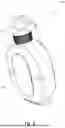
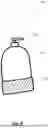
FIG. 1 illustrates a perspective view of an apparatus for dispensing liquid and volatile material, according to an exemplary embodiment of the present invention.
FIG. 2 illustrates another perspective view of the apparatus, according to an exemplary embodiment of the present invention.
FIG. 3 illustrates the apparatus with a transparent container to reveal internal components, according to an exemplary embodiment of the present invention.
FIG. 4 illustrates an exploded view of the apparatus, according to an exemplary embodiment of the present invention.
FIG. 5 illustrates another exploded view of the apparatus, according to an exemplary embodiment of the present invention.
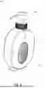
FIG. 6 illustrates a volatile material module mounded to a side of a container of the apparatus, according to an exemplary embodiment of the present invention.
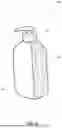
FIG. 7 illustrates the volatile material module mounded to a top of the container of the apparatus, according to an exemplary embodiment of the present invention.
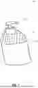
FIG. 8 illustrates the volatile material module mounded to a bottom of the container of the apparatus, according to an exemplary embodiment of the present invention.
FIG. 9 illustrates the volatile material module as a coating or layer over the container of the apparatus, according to an exemplary embodiment of the present invention.
DETAILED DESCRIPTION
Subject matter will now be described more fully hereinafter with reference to the accompanying drawings, which form a part hereof, and which show, by way of illustration, specific exemplary embodiments. Subject matter may, however, be embodied in a variety of different forms and, therefore, covered or claimed subject matter is intended to be construed as not being limited to any exemplary embodiments set forth herein; exemplary in embodiments are provided merely to be illustrative. Likewise, a reasonably broad scope for claimed or covered subject matter is intended. Among other things, for example, the subject matter may be embodied as methods, devices, components, or systems. The following detailed description is, therefore, not intended to be taken in a limiting sense.
The word “exemplary” is used herein to mean “serving as an example, instance, or illustration.” Any embodiment described herein as “exemplary” is not necessarily to be construed as preferred or advantageous over other embodiments. Likewise, the term “embodiments of the present invention” does not require that all embodiments of the invention include the discussed feature, advantage, or mode of operation.
The terminology used herein is to describe particular embodiments only and is not intended to be limiting to embodiments of the invention. As used herein, the singular forms “a”, “an” and “the” are intended to include the plural forms as well, unless the context clearly indicates otherwise. It will be further understood that the terms “comprises”, “comprising,”, “includes” and/or “including”, when used herein, specify the presence of stated features, integers, steps, operations, elements, and/or components, but do not preclude the presence or addition of one or more other features, integers, steps, operations, elements, components, and/or groups thereof.
The following detailed description includes the best currently contemplated mode or modes of carrying out exemplary embodiments of the invention. The description is not to be taken in a limiting sense but is made merely to illustrate the general principles of the invention since the scope of the invention will be best defined by the allowed claims of any resulting patent.
Disclosed herein is an apparatus for dispensing liquid and volatile materials, and a method of use thereof. The apparatus generally comprises a liquid dispensing unit and a volatile material module, wherein the volatile material module is mountable to the liquid dispensing unit.
The liquid dispensing unit includes a container for containing a liquid product such as bathing soap, hand soap, lotion, dish soap, shampoo, sanitizer, or any other suitable fluid. The container may be formed of any appropriate material including, without limitation, plastics such as HDPE, PP, PETG, ABS, or acrylic; glass; metal; wood; or paperboard laminate. The container may take various shapes for functional or aesthetic purposes, e.g., cylindrical, cuboidal, or ornamental forms, and typically defines a flat base. The outer surface of the container may include decorative designs, coatings, or textures. The container may be transparent, semi-transparent, or opaque.
Referring now to FIGS. 1-5, exemplary embodiments of the apparatus 100 are illustrated. FIGS. 1-2 illustrate perspective views of the apparatus 100. FIG. 3 illustrates a transparent container 110 to show internal components. FIGS. 4-5 illustrate exploded views of the apparatus 100, including a liquid dispensing unit 105 having container 110 and pump assembly 120.
The pump assembly 120 may be of a manual or electronic type, as known in the art, and may be mounted to a mouth of the container 110. A dip tube or pipe 140 extends into the container to dispense liquid.
FIG. 1 illustrates an embodiment of the apparatus 100 including a container 110 having a broad shape with relatively narrow thickness. The container 110 defines a central cavity 150, or through-bore, configured to receive a removable or integral volatile material module 130. A dip tube or pipe 140 of the pump assembly 120 is routed along the central cavity 150 and extends to the bottom of the container 110 for dispensing liquid product. It is to be noted that, unless expressly stated otherwise, reference to the term “cavity” hereinafter also encompasses a through-bore.
The volatile material module 130 can be mounted within the central cavity 150 as illustrated in FIG. 1. It is to be noted that the depiction of the central cavity 150 receiving the volatile material module 130 is provided for illustration only, and it will be understood by a person skilled in the art that the cavity may be positioned at alternative locations in the container 110. For example, the cavity may be formed at a side wall, the base, or the top of the container 110. Such cavities are likewise configured to receive the volatile material module 130, and both the shape and size of the cavity and the volatile material module may be varied without departing from the scope of the present invention.
The volatile material module 130 includes a receptacle 160, a carrier 170, and a cap 180. The receptacle 160 is dimensioned to fit within the central cavity 150 of the container 110 and comprises a base and a wall extending upwardly from the base, the base and wall together defining an inner volume of the receptacle 160. The carrier 170 is disposed within the inner volume of the receptacle 160 and is configured to retain a volatile composition. The cap 180 is coupled to an opening of the receptacle 160 to secure the carrier 170 within the receptacle 160. The cap 180 includes one or more slots or apertures that allow controlled release of the volatile composition from the carrier 170 into surrounding air.
The carrier 170 contains the volatile material, which is gradually released into the surrounding environment over an extended period of time. The volatile material may include, by way of example, a fragrance, essential oil, deodorizer, malodor counteractant, odor-neutralizing chemistry, antimicrobial vapor, or insect repellent, either individually or in any combination thereof.
The volatile material module 130 is insertable into the cavity 150 of the container 110. In one arrangement, one side of the cavity 150 receives a base portion of the receptacle 160, while an opposite side of the cavity 150 is aligned with the slotted cap 180, thereby allowing the volatile material to escape into surrounding air. The volatile material module 130 may be secured within the cavity 150 by a locking mechanism such as a bayonet interface, threaded connection, snap-fit, or magnetic retention. In certain embodiments, the volatile material module 130 further includes circumferential vents that can be selectively opened or closed by a rotating band to regulate emission. Structural ribs may be provided around the cavity 150 to maintain the mechanical integrity of the container 110.
Various surface treatments, textures, and coatings may be applied to the outer surface of the receptacle 160 and the cap 180 to enhance aesthetic appearance, provide branding opportunities, or improve tactile feel for the user.
The cap 180 of the volatile material module 130 may include one or more holes, slots, or apertures, the number, size, and arrangement of which can be varied. The quantity of volatile material released into the air is generally proportional to the number or total area of the apertures exposed at a given time. The apertures can be selectively controlled to be fully open, partially open, or fully closed, thereby allowing the user to adjust the level of fragrance diffusion according to preference.
In certain implementations, the volatile material module 130 can be refilled or recharged when the volatile material in the receptacle 160 is depleted. For example, the module 130 can be removed from the container 110 and the cap 180 detached to expose the carrier 170. Additional volatile material can then be introduced into the carrier 170, or the carrier 170 itself can be replaced with a new carrier preloaded with volatile material. It is to be noted that the carrier 170 may be substituted by any other controlled-release mechanism suitable for dispensing volatile material.
In certain implementations, the carrier 170 may employ one or more controlled-release media including, but not limited to, gels, polymer beads (e.g., EVA, SEBS), saturated wicks or pads (e.g., cellulose, ceramic), porous minerals (e.g., zeolites), waxes, microencapsulated oils in a binder, and/or liquid reservoirs positioned behind permeable membranes (e.g., microperforated PE/PP, ePTFE). Typical active loadings of the volatile material within such carriers can range from approximately 0.1% to 60% by weight. To ensure freshness, safety, and extended shelf life, refill cartridges may be hermetically sealed using foil, film, or equivalent barrier materials until activation.
In certain implementations, the volatile material module 130 may include a removable sealing element, such as a sticker or film, positioned over the holes of the cap 180. The sealing element prevents premature release of the volatile material during storage and transport. Upon removal by the user, the holes are exposed, thereby permitting diffusion of the volatile material into the atmosphere.
In certain implementations, the volatile material module 130 may be configured as a replaceable cartridge. For example, the exhausted module can be removed and replaced with a new volatile material module 130. In either case, the module can be hermetically or otherwise sealed to prevent leakage or premature volatilization of the active material. Different modules containing different types of volatile materials or fragrances may be interchangeably used with the same apparatus, thereby allowing user customization and flexibility.
In certain implementations, the volatile material module 130 may further include a mechanical control element, such as a slider or lever, incorporated on a side of the receptacle 160 or cap 180. Movement of the slider or lever between positions selectively reveals or conceals the holes in the cap, thereby regulating the diffusion rate of the volatile material into the surrounding atmosphere.
In certain implementations, the release of volatile materials may be selectively controlled through one or more adjustable mechanisms. Such mechanisms can include, but are not limited to: rotational sleeves or bands with windows that align with cap apertures (optionally incorporating detents at preset levels); linear sliders or iris shutters that modulate the open area; peelable or punch-through membranes enabling step-wise activation; variable-porosity films; wick exposure adjustment mechanisms (e.g., raising or lowering a cap to expose more of the wick); and microcapsule coatings that are activated by touch, friction, or other mechanical stimuli.
In certain implementations, the volatile material module 130 may include one or more pushbuttons or actuators, wherein activation of the pushbutton mechanically or electronically opens a vent or triggers the release of a controlled burst of volatile material. This configuration simplifies user operation and enables instant or on-demand fragrance release as needed.
In certain implementations, the volatile material module 130 may include a dial mechanism configured to adjust the release of volatile material. Rotation of the dial selectively varies the exposed area of the cap holes, thereby controlling the rate of diffusion. This mechanism provides the user with precise control over the intensity of the released fragrance.
n certain implementations, the volatile material module 130 may include a secondary cap without holes, which can be applied to cover or seal the holes of the primary cap 180. The secondary cap may also serve as a replacement for the primary cap. Various mechanisms for controlling the release of volatile material may be employed in combination with or independent of the secondary cap, including, but not limited to, shutters, sliders, rotating sleeves, peelable or puncturable membranes, vent alignment, wick exposure adjustment, and variable-porosity pathways.
In certain implementations, the container 110 and/or receptacle 160 may be primarily constructed from high-quality, chemically non-reactive materials, such as plastics, to ensure durability and prevent adverse interaction with the contained liquids or volatile materials. The apparatus may be ergonomically designed to enhance user comfort and handling. For example, the base of the receptacle 160 may incorporate textures, ribs, or other surface features to improve grip, even when hands are wet. Additionally, the dispensing or pump mechanism 120 may be configured to operate with minimal actuation force, thereby reducing user strain during repeated use.
In certain implementations, the apparatus may further include a visual indicator integrated into the receptacle 160. The visual indicator may comprise, for example, a color-changing element, such as a thermochromic material, which responds to the intensity or rate of volatile material release as set by the user. The indicator provides a visual cue of the current fragrance output, allowing the user to quickly ascertain the operational status of the volatile material module 130.
In certain implementations, the apparatus may further include a lock mechanism for the pump mechanism 120. The lock mechanism may serve as a safety feature, particularly in households with children, and when engaged, it prevents both the dispensing of liquid from the container 110 and the release of volatile material from the module 130. This configuration enhances user safety by inhibiting unintended operation of the apparatus.
In certain implementations, the base of the apparatus 110 may include a non-slip feature to prevent unintended movement or slipping on wet or smooth surfaces. The non-slip feature may comprise, for example, a rubber, silicone, or other high-friction material integrated into or attached to the base, thereby enhancing stability during use.
In certain implementations, the apparatus may include a spray mechanism for actively dispersing volatile material. The spray mechanism may be manually actuated via a button to release a controlled burst of fragrance. Alternatively, the spray mechanism may be battery-operated or electrically powered to periodically or automatically release fragrance. For example, the fragrance release may be synchronized with the actuation of the pump mechanism 120, such that a burst of fragrance is dispersed each time liquid is dispensed from the container 110.
In certain implementations, the receptacle 160 of the volatile material module 130 may adopt a carousel-style design comprising multiple compartments, each containing a different volatile material or fragrance. The user may rotate the cap 180 or the receptacle 160 to selectively align a desired compartment for release, thereby allowing the user to switch between fragrances according to preference.
The disclosed apparatus 100 may be used in restrooms and other locations where handwashing or liquid dispensing occurs. By integrating a fragrance or volatile material module 130 with the liquid dispensing unit 120, the apparatus provides both hygiene and an enhanced sensory experience. The combined functionality eliminates the need for a separate air freshener unit, thereby reducing clutter and optimizing space utilization.
The disclosed apparatus 100 may also be used in kitchens and other areas where food preparation or handling occurs. After contact with odorous substances such as garlic, onions, or fish, washing hands may leave residual scents. The integrated volatile material module 130 actively counteracts such odors, helping maintain a clean and pleasant environment. In certain implementations, the automatic release of fragrance may be synchronized with actuation of the pump mechanism 120, thereby providing aroma only when the apparatus is in use and minimizing unnecessary release when the area is unoccupied.
In certain implementations, the disclosed apparatus 100 may also be used in laundry rooms or other compact utility spaces. During tasks such as pre-treating garments or washing hands after handling soiled items, the integrated liquid and volatile material dispensers provide both cleanliness and a refreshing environment, enhancing the user experience in otherwise confined areas.
similar to residential settings, restrooms in offices and commercial establishments may benefit from the disclosed apparatus 100. By combining a liquid dispensing unit with an adjustable volatile material module, employees, visitors, and patrons experience both hygiene and a pleasant atmosphere. In dining establishments, such as cafés and restaurants, providing a consistent and pleasant restroom experience can enhance the perception of the brand. Guest rooms, suites, and public restrooms may incorporate the disclosed apparatus to deliver a combination of practicality and luxury. High-traffic public restrooms, such as those in malls, benefit from continuous hygiene and fragrance dispensing, improving the overall visitor experience. In clinical and medical environments where hand hygiene is critical, the apparatus 100 may provide necessary soap while introducing a calming or neutralizing fragrance, mitigating the clinical odor and creating a more comfortable atmosphere for patients. Dental clinics, in particular, may benefit from the volatile material module to neutralize residual odors after handwashing.
The disclosed apparatus 100 may also be used in educational institutions, such as schools, colleges, and boarding facilities, to promote proper hand hygiene while maintaining a fresh environment in shared spaces. In daycare centers, where young children may require frequent reminders to wash their hands, the integrated liquid dispensing unit 120 and volatile material module 130 can make handwashing more engaging, ensuring both cleanliness and a pleasant atmosphere for children and caregivers alike.
The disclosed apparatus 100 may also be used in spas and wellness centers, where the emphasis is on relaxation. After treatments or therapies, clients can wash their hands while simultaneously enjoying a calming fragrance, enhancing the overall relaxation experience. Similarly, in gyms and fitness centers, members can refresh themselves after a workout by washing their hands and experiencing a rejuvenating scent, promoting a sense of cleanliness and post-activity freshness.
The disclosed apparatus 100 conserves counter space by combining the functions of liquid dispensing and fragrance release into a single unit. The apparatus enhances the handwashing experience by ensuring a pleasant aroma accompanies the washing process. Furthermore, users may adjust the fragrance intensity according to personal preference, providing a customizable and enjoyable experience.
In certain implementations, the disclosed apparatus 100 may provide a continuous release of a small quantity of fragrance through one or more of the mechanisms described herein. For example, a subset of apertures in the fragrance dispensing unit 130 can be exposed to allow a steady, low-level emission of fragrance sufficient to maintain a fresh environment. Additionally, the apparatus 100 may be configured to release a burst of fragrance upon actuation of the pump mechanism 120 for dispensing liquid. Accordingly, the apparatus 100 may incorporate two or more fragrance-release mechanisms, including a continuous emission mode and an actuation-triggered burst mode, enhancing both convenience and environmental freshness.
In certain implementations, the container 110 preferably defines a central cavity 150, or through-bore, configured to receive a removable or integral volatile material module 130. It is noted that any reference to the term “cavity” herein includes a through-bore. The cavity 150 may accommodate a cylindrical core or toroidal insert. The volatile material module 130 may be secured within the cavity 150 via bayonet, threaded, snap, or magnetic retention mechanisms, and may include circumferential vents gated by a rotating band. Structural ribs maintain the integrity of the container 110 around the cavity 150, while continuous barrier walls and seals ensure separation between liquid and volatile material volumes.
In certain implementations, the volatile material module may be positioned laterally. A lateral module can be affixed to an exterior sidewall of the container 110 via an integrally molded rail or dovetail, a circumferential band or collar located below the shoulder, adhesive pads with secondary clips, or magnetic couplers comprising a magnet and steel insert. The module may be repositionable among multiple rails or bands. The vents of the module may be oriented outward or upward, and emission control may be provided via a slider or a rotating shell. Lateral placement enables the use of larger cartridges without increasing the overall height of the container.
In certain implementations, the volatile material module may be positioned on the top of the container, including on the closure, collar, or overcap. A ring-shaped cavity within the overcap, pump collar, or ferrule houses the volatile material. An external crown or bezel may be rotated to align or occlude vent openings, thereby controlling the release of the volatile material. The liquid pump path is separated from the volatile material module by fixed partitions and elastomeric gaskets to prevent cross-contamination. An optional top module may be independently removable for refilling without disturbing the liquid closure.
In certain implementations, the volatile material module may be positioned at the bottom of the container, such as in the base, foot, or pedestal. A base compartment or foot ring may accommodate a volatile material cartridge. The emission of the volatile material may be adjusted using twist-to-reveal caps, sliders, or lift-and-turn mechanisms with tactile detents (e.g., 0/25/50/75/100%). Anti-slip feet and labyrinth channels may be incorporated to reduce the risk of leakage. The base may be removable to allow cartridge replacement or may include a small access door while remaining integral to the container.
In certain implementations, the air-freshening function may be realized by an exterior coating or shell applied over part or all of the container 110. Examples include an overmolded (two-shot) scented TPE, TPU, or SEBS layer; a film, sleeve, or wrap (e.g., shrink sleeve) containing microencapsulated actives; spray or dip coatings comprising a binder with microcapsules; or removable elastomeric sleeves pre-loaded with actives. Emission of the volatile material may be controlled using variable porosity, microperforation patterns, peelable windows, or an outer sliding band that aligns over perforated regions. Typical shell thickness may range from approximately 25 μm to 2,000 μm.
In certain implementations, any combination of module positions may be used concurrently (e.g., top and bottom, side and coated shell). A family of standardized interfaces may permit a user to transfer a volatile material cartridge from one location to another (e.g., from a side rail to a top collar), optionally using adaptor rings or collars. Keying features and alignment marks may be provided to ensure proper assembly and orientation.
Example A (Donut Core): A 350 mL annular bottle with a 25-40 ml central cartridge; a perforated sleeve around the core rotates between closed and fully open; bayonet retention; dual silicone O-rings at core ends.
Example B (Sidecar Rail): A 500 mL cylindrical bottle with an integrally molded rail; a 30 mL side module snaps on; a linear slider gates three vent rows; first-use foil under a vent bezel; module can be moved to a top adaptor ring.
Example C (Top Crown): A pump collar with an annular volatile cavity and a rotatable crown bezel that aligns decorative apertures over microperforations; pump path sealed by partitions and gaskets; volatile refill accessed by lifting the crown.
Example D (Base Pedestal): A twist-to-reveal bottom module with detents at 0/25/50/75/100% open area; anti-slip pads; a labyrinth channel between volatile cavity and reservoir wall; cartridge swaps from below.
Example E (Coated Sleeve): A shrink sleeve bearing microencapsulated fragrance domains over perforated zones; an external sliding band partially occludes the zones to adjust emission; sleeve is removable, recyclable, and SKU-coded.
The embodiments described herein are illustrative and non-limiting. Features disclosed with respect to one module position may be combined with features of other positions. Dimensions, materials, vent geometries, and assembly methods may vary without departing from the scope of the invention. Optional electronics, such as fans, heaters, timers, or sensors, may be included but are not required. Where numerical ranges are provided, all endpoints and subranges are intended to be encompassed. All equivalents of the described features are intended to fall within the scope of the appended claims of any subsequently filed non-provisional application.
Referring to FIG. 6, which illustrates an exemplary embodiment of the disclosed apparatus, an apparatus 600 is shown comprising a container 610 and an actuation mechanism 620 mounted at an opening of the container 610 for dispensing liquid contained therein. A volatile material module 630 is mounted to a side of the container 610. In one embodiment, one side of the container 610 may be substantially flat, and the volatile material module 630 may be mounted to this flat side. However, the container 610 is not limited to having a flat side, and the volatile material module 630 may be configured to correspond to any alternative shape of the container 610. The volatile material module 630 may be formed integrally with the container 610 or may be removably attached thereto using any suitable fastening mechanism as described above.
Referring to FIG. 7, which illustrates an exemplary embodiment of the disclosed apparatus, an apparatus 700 is shown comprising a container 710 and an actuation mechanism 720. A volatile material module 730 is mounted to a top portion of the container 610. In one embodiment, a top portion of the container 610 may be substantially flat, and the volatile material module 630 may be mounted to this flat side. However, the container 710 is not limited to having a flat side, and the volatile material module 730 may be configured to correspond to any alternative shape of the container 710. The volatile material module 730 may be formed integrally with the container 710 or may be removably attached thereto using any suitable fastening mechanism as described above. The volatile material module 730 may have a hollow tunnel that is continuous with the mouth of the container, and the actuation mechanism can be mounted at an opening of the hollow tunnel for dispensing liquid contained therein. Alternatively, the mouth of the container may extend through the hollow tunnel, and the actuation mechanism can be mounted to the mouth of the container.
Referring to FIG. 8, which illustrates an exemplary embodiment of the disclosed apparatus, an apparatus 800 is shown comprising a container 810 and an actuation mechanism 820 mounted at an opening of the container 810 for dispensing liquid. The volatile material module 830 may be formed integrally with the container 810 or may be removably attached thereto using any suitable fastening mechanism as described above.
Referring to FIG. 9, which illustrates an exemplary embodiment of the disclosed apparatus, an apparatus 900 is shown comprising a container 910 and an actuation mechanism 920 mounted at an opening of the container 910 for dispensing liquid. The volatile material module 930 may be formed in the form of a coating over the body of the container 910.
While the foregoing written description of the invention enables one of ordinary skill to make and use what is considered presently to be the best mode thereof, those of ordinary skill will understand and appreciate the existence of variations, combinations, and equivalents of the specific embodiment, method, and examples herein. The invention should therefore not be limited by the above-described embodiment, method, and examples, but by all embodiments and methods within the scope and spirit of the invention as claimed.
Claims
What is claimed is:1. An apparatus for dispensing a liquid product and a volatile material, the apparatus comprising:
a container defining a reservoir for holding a liquid product;
a pump assembly mounted to a mouth of the container and configured to dispense the liquid product from the reservoir; and
a volatile material module integrated with or mountable to the container, the volatile material module comprising a receptacle configured to contain a volatile composition and a cap having one or more openings to allow release of the volatile composition into surrounding air.
2. The apparatus of claim 1, wherein the volatile material module is located in a cavity formed in the container.
3. The apparatus of claim 2, wherein the cavity is a central cavity extending through the container.
4. The apparatus of claim 3, wherein the receptacle is configured to fit within the central cavity, and the volatile material module is removable, refillable, or replaceable.
5. The apparatus of claim 4, wherein the volatile material module further comprises a carrier disposed in the receptacle, the carrier configured to retain the volatile composition for controlled release.
6. The apparatus of claim 3, wherein the cap is aligned with a front side of the container, and a base of the receptacle is aligned with a rear side of the container.
7. The apparatus of claim 5 wherein the receptacle comprises the base and wall upstanding from the base, wherein the base and the wall defines an inner volume of the receptacle, wherein the carrier is received within the inner volume of the receptacle and an opening of the receptacle is closed by the cap.
8. The apparatus of claim 1, wherein the volatile material module is mounted to a top portion, a side, or a bottom portion of the container.
9. The apparatus of claim 1, wherein the volatile material module is formed as a layer over the container.
10. A method of dispensing a liquid product and a volatile material, the method comprising:
providing an apparatus comprising:
a container defining a reservoir for holding a liquid product,
a pump assembly mounted to a mouth of the container and configured to dispense the liquid product from the reservoir, and
a volatile material module integrated with or mountable to the container, the volatile material module comprising a receptacle configured to contain a volatile composition and a cap having one or more openings to allow release of the volatile composition into surrounding air;
actuating the dispensing assembly to dispense the liquid product; and
releasing the volatile material from the volatile material module into surrounding air through the cap.
11. The method of claim 10, wherein the volatile material module is located in a cavity formed in the container.
12. The method of claim 11, wherein the cavity is a central cavity extending through the container, wherein the method further comprises:
inserting the volatile material module into the central cavity.
13. The method of claim 12, wherein the receptacle is configured to fit within the central cavity, and the volatile material module is removable, refillable, or replaceable.
14. The method of claim 13, wherein the volatile material module further comprises a carrier disposed in the receptacle, the carrier configured to retain the volatile composition for controlled release.
15. The apparatus of claim 12, wherein the cap is aligned with a front side of the container, and a base of the receptacle is aligned with a rear side of the container.
16. The method of claim 14 wherein the receptacle comprises the base and wall upstanding from the base, wherein the base and the wall defines an inner volume of the receptacle, wherein the carrier is received within the inner volume of the receptacle and an opening of the receptacle is closed by the cap.
17. The method of claim 10, wherein the volatile material module is mounted to a top portion, a side, or a bottom portion of the container.
18. The method of claim 10, wherein the volatile material module is formed as a layer over the container.
Images & Drawings included:


Sources:
- United States Patent and Trademark Office - verify current appl. status at the USPTO↗
Recent applications in this class:
- » 20260013677 2026-01-15
WALL MOUNTED DISPENSER - » 20250375067 2025-12-11
Fluid Dispenser With Moveable Nozzle Shield For Manual Activation - » 20250194862 2025-06-19
CONTAINER AND PUMP ASSEMBLY THEREOF - » 20250107672 2025-04-03
TOP-FILL COUNTER-MOUNT SOAP DISPENSERS - » 20250009189 2025-01-09
REPLACEMENT DISPENSER ASSEMBLY AND REPLENISHING METHOD FOR MOUNTABLE REPLENISHABLE DISPENSING SYSTEM - » 20240398174 2024-12-05
PRODUCT DISPENSER IN GEL OR CREAM FORM - » 20240382046 2024-11-21
Wall Mounted Dispenser - » 20240366037 2024-11-07
LOCKABLE RECEPTACLE HOLDER - » 20240341542 2024-10-17
Mountable replenishable dispensing system - » 20240268608 2024-08-15
DOSE ADJUSTABLE DISPENSING SYSTEM AND METHODS OF USING AND ASSEMBLING THE SAME