SURFACE CLEANING APPARATUS
US20260053314A1
2026-02-26
18/812,825
2024-08-22
Smart Summary: A hand vacuum cleaner is designed to clean surfaces effectively. It has a front and rear end, with air flowing from a dirty air inlet to a clean air outlet. Inside, there is a motor and fan, along with a cyclone assembly that separates dirt from the air. The cyclone assembly includes a chamber for air and another for collecting dirt, with an opening that can be moved to access the dirt chamber. This design allows for easy cleaning and maintenance of the vacuum cleaner. 🚀 TL;DR
Abstract:
A hand vacuum cleaner has a front end, a rear end, a vacuum axis extending between the front and rear ends, and an air flow path extending from a dirty air inlet to a clean air outlet. A motor and fan assembly and a cyclone assembly are provided in the air flow path. The cyclone assembly has a cyclone chamber and a dirt chamber. The cyclone chamber has an air inlet, an air outlet, a dirt outlet to the dirt chamber, and a cyclone axis. When the vacuum axis is horizontal, the cyclone axis is horizontal and extends transversely to the vacuum axis, and the cyclone chamber has a sidewall extending transversely between opposed end walls. A front end of the cyclone assembly has an openable portion which is moveably mounted between a closed position and an open position in which the cyclone chamber and the dirt chamber are opened.
Applicant:
Interested in similar patents?
Get notified when new applications in this technology area are published.
Classification:
A47L9/1608 » CPC main
Details or accessories of suction cleaners, e.g. mechanical means for controlling the suction or for effecting pulsating action; Storing devices specially adapted to suction cleaners or parts thereof; Carrying-vehicles specially adapted for suction cleaners; Filters ; Dust separators; Dust removal; Automatic exchange of filters; Arrangement or disposition of cyclones or other devices with centrifugal action Cyclonic chamber constructions
A47L5/24 » CPC further
Structural features of suction cleaners with power-driven air-pumps or air-compressors, e.g. driven by motor vehicle engine vacuum with rotary fans Hand-supported suction cleaners
A47L9/1666 » CPC further
Details or accessories of suction cleaners, e.g. mechanical means for controlling the suction or for effecting pulsating action; Storing devices specially adapted to suction cleaners or parts thereof; Carrying-vehicles specially adapted for suction cleaners; Filters ; Dust separators; Dust removal; Automatic exchange of filters; Arrangement or disposition of cyclones or other devices with centrifugal action; Construction of outlets with filtering means
A47L9/16 IPC
Details or accessories of suction cleaners, e.g. mechanical means for controlling the suction or for effecting pulsating action; Storing devices specially adapted to suction cleaners or parts thereof; Carrying-vehicles specially adapted for suction cleaners; Filters ; Dust separators; Dust removal; Automatic exchange of filters Arrangement or disposition of cyclones or other devices with centrifugal action
Description
FIELD
This disclosure relates generally to surface cleaning apparatus. In a preferred embodiment, the surface cleaning apparatus comprises a portable surface cleaning apparatus, such as a hand vacuum cleaner.
INTRODUCTION
The following is not an admission that anything discussed below is part of the prior art or part of the common general knowledge of a person skilled in the art.
Various types of surface cleaning apparatus are known, including upright surface cleaning apparatus, canister surface cleaning apparatus, stick surface cleaning apparatus, central vacuum systems, and hand carriable surface cleaning apparatus such as hand vacuums. Further, various designs for cyclonic hand vacuum cleaners, including battery operated cyclonic hand vacuum cleaners, are known in the art.
SUMMARY
This summary is intended to introduce the reader to the more detailed description that follows and not to limit or define any claimed or as yet unclaimed invention. One or more inventions may reside in any combination or sub-combination of the elements or process steps disclosed in any part of this document including its claims and figures.
In accordance with one aspect of this disclosure, which may be used alone or in combination with any other aspect, a hand vacuum cleaner has a hand vacuum cleaner axis that extending centrally through the hand vacuum cleaner between the front and rear ends of the hand vacuum cleaner. The hand vacuum cleaner includes a cyclone chamber and a dirt collection chamber exterior to the cyclone chamber. The cyclone chamber has a cyclone axis of rotation which, when the hand vacuum cleaner axis is oriented horizontally, the cyclone axis of rotation is oriented generally horizontally. The front end of the cyclone assembly has an openable portion which is moveably mounted by a mount between a closed position, in which the hand vacuum cleaner is operable to clean a surface, and an open position, in which the cyclone chamber and optionally the dirt collection chamber are opened. The mount is provided between the mid-line of the height of the cyclone assembly and the top of the cyclone assembly.
In accordance with this aspect, there is provided a hand vacuum cleaner having a front end, a rear end and a hand vacuum cleaner axis extending centrally through the hand vacuum cleaner between the front and rear ends, the hand vacuum cleaner comprising:
-
- (a) an air flow path extending from a dirty air inlet provided at the front end of the hand vacuum cleaner to a clean air outlet, which is positioned rearward of the dirty air inlet, with a motor and fan assembly provided in the air flow path;
- (b) a cyclone assembly provided in the air flow path, the cyclone assembly comprising a cyclone chamber and a dirt collection chamber exterior to the cyclone chamber, the cyclone chamber comprising a cyclone air inlet, a first cyclone air outlet, a dirt outlet in communication with the dirt collection chamber and a cyclone axis of rotation; and,
- (c) a handle,
- wherein, when the hand vacuum cleaner axis is oriented horizontally, the cyclone axis of rotation is oriented generally horizontally and extends generally transverse to the hand vacuum cleaner axis and the cyclone chamber comprises a first end wall, an opposed second end wall and a cyclone sidewall extending transversely between the first and second end walls, and
- wherein, when the hand vacuum cleaner is oriented with the dirty air inlet provided at an upper end of the hand vacuum cleaner and the hand vacuum cleaner axis is oriented horizontally, the hand vacuum cleaner has a lower end, the cyclone chamber has a lower end, an upper end and a mid-line positioned at an elevation equidistantly between a bottom of the cyclone chamber and a top of the cyclone chamber and the dirt collection chamber has a lower end, and
- wherein a front end of the cyclone assembly has an openable portion which is moveably mounted by a mount between a closed position, in which the hand vacuum cleaner is operable to clean a surface, and an open position, in which the cyclone chamber and the dirt collection chamber are opened, and the mount is provided between the mid line and the top of the cyclone chamber.
In accordance with another aspect of this disclosure, which may be used alone or in combination with any other aspect, a hand vacuum cleaner includes a cyclone chamber and a dirt collection chamber exterior to the cyclone chamber which, as discussed with respect to the previous embodiment, has a cyclone axis of rotation that extends generally transverse to the hand vacuum cleaner axis. In accordance with this aspect, at least a portion of the dirt collection chamber is positioned below the cyclone chamber and optionally the dirt outlet from the cyclone chamber may be in a lower portion of the cyclone chamber.
In accordance with this aspect, there is provided a hand vacuum cleaner having a front end, a rear end and a hand vacuum cleaner axis extending centrally through the hand vacuum cleaner between the front and rear ends, the hand vacuum cleaner comprising:
-
- (a) an air flow path extending from a dirty air inlet provided at the front end of the hand vacuum cleaner to a clean air outlet, which is positioned rearward of the dirty air inlet, with a motor and fan assembly provided in the air flow path;
- (b) a cyclone assembly provided in the air flow path, the cyclone assembly comprising a cyclone chamber and a dirt collection chamber exterior to the cyclone chamber, the cyclone chamber comprising a cyclone air inlet, a first cyclone air outlet, a dirt outlet in communication with the dirt collection chamber and a cyclone axis of rotation; and,
- (c) a handle,
- wherein, when the hand vacuum cleaner axis is oriented horizontally, the cyclone axis of rotation is oriented generally horizontally and extends generally transverse to the hand vacuum cleaner axis and the cyclone chamber comprises a first end wall, an opposed second end wall and a cyclone sidewall extending transversely between the first and second end walls, and
- wherein, when the hand vacuum cleaner is oriented with the dirty air inlet provided at an upper end of the hand vacuum cleaner and the hand vacuum cleaner axis is oriented horizontally, the hand vacuum cleaner as a lower end, the cyclone chamber has a lower end, an upper end and a mid-line positioned at an elevation equidistantly between a bottom of the cyclone chamber and a top of the cyclone chamber, the dirt collection chamber has a lower end and at least a portion of the dirt collection chamber is positioned below the cyclone chamber.
In accordance with another aspect of this disclosure, which may be used alone or in combination with any other aspect, a hand vacuum cleaner includes a cyclone chamber and a dirt collection chamber exterior to the cyclone chamber which, as discussed with respect to a previous embodiment, has a cyclone axis of rotation that extends generally transverse to the hand vacuum cleaner axis. In accordance with this aspect, one or more of the following may be provided:
(1) The cyclone assembly may have an openable portion that is moveable mounted to the cyclone assembly by a mount provided on the cyclone and optionally a transversely extending sidewall of the cyclone.
(2) The mount may be located at or rearward of the cyclone axis of rotation.
(3) A second separation stage comprising a second stage air treatment chamber (which may be non-cyclonic or cyclonic) and a second stage dirt collection region, which may be a second stage dirt collection region that is exterior to the second stage air treatment chamber, may be provided. The second stage dirt collection region may be concurrently openable with the first stage dirt collection region. Alternately, or in addition, the second separation stage may comprise one or more cyclones in parallel which have a cyclone axis of rotation that extends generally transverse to the hand vacuum cleaner axis.
(4) The cyclone assembly has a front wall and the front wall remains in position when the openable portion is opened.
(5) The cyclone assembly comprises a sweeping arm which moves through a portion of the first stage dirt collection chamber when the openable portion is opened.
(6) The cyclone assembly may have a second openable portion. One of the openable portions may be used to empty the cyclone assembly when the cyclone assembly (or hand vacuum cleaner) is docked at a docking station. The second openable portion may not be configured for mating with a docking station and may be operable by a user to empty the cyclone assembly without using a docking station. Accordingly, the first and second openable portions may be independently openable.
(7) A vortex finder may be provided on the end of a cyclone chamber opposed to the air outlet end of the cyclone chamber (e.g., on the end wall that is opposed to and faces the air outlet of the cyclone chamber).
(8) The cyclone chamber air inlet may be located midway between the axially opposed end walls of the cyclone chamber. Accordingly, the cyclone axis of rotation may intersect the first and second opposed end walls and the cyclone air outlet may be provided in the first end wall or a cyclone air outlet may be provided in each of the first and second opposed end walls.
(9) The hand vacuum cleaner may have a finger guard with an operating component of the hand vacuum cleaner in the finger guard, such as the motor and fan assembly or an energy storage member or members.
In any embodiment, the openable portion may include a portion of a wall of the first stage dirt collection chamber and/or a portion of the sidewall of the first stage cyclone chamber.
In accordance with this aspect, there is provided a hand vacuum cleaner having a front end, a rear end and a hand vacuum cleaner axis extending centrally through the hand vacuum cleaner between the front and rear ends, the hand vacuum cleaner comprising:
-
- (a) an air flow path extending from a dirty air inlet provided at the front end of the hand vacuum cleaner to a clean air outlet, which is positioned rearward of the dirty air inlet, with a motor and fan assembly provided in the air flow path;
- (b) a cyclone assembly provided in the air flow path, the cyclone assembly comprising a first cyclonic stage, the first cyclonic stage comprising a first stage cyclone chamber and a first stage dirt collection chamber exterior to the first stage cyclone chamber, the first stage cyclone chamber comprising a cyclone air inlet, a first cyclone air outlet, a dirt outlet in communication with the first stage dirt collection chamber and a cyclone axis of rotation; and,
- (c) a handle,
- wherein, when the hand vacuum cleaner axis is oriented horizontally, the cyclone axis of rotation is oriented generally horizontally and extends generally transverse to the hand vacuum cleaner axis and the first stage cyclone chamber comprises a first end wall, an opposed second end wall and a cyclone sidewall extending transversely between the first and second end walls, and
- wherein the cyclone assembly has an openable portion which is moveably mounted by a mount between a closed position in which the hand vacuum cleaner is operable to clean a surface, and an open position in which the first stage cyclone chamber and the first stage dirt collection chamber are opened, the openable portion comprises a portion of a wall of the first stage dirt collection chamber and a portion of the sidewall of the first stage cyclone chamber, wherein the mount is provided on the sidewall of the first stage cyclone chamber, or
- wherein, when the hand vacuum cleaner axis is oriented horizontally, the cyclone axis of rotation is oriented generally horizontally and extends generally transverse to the hand vacuum cleaner axis and the first stage cyclone chamber comprises a first end wall, an opposed second end wall and a cyclone sidewall extending transversely between the first and second end walls, and
- wherein the cyclone assembly has an openable portion which is moveably mounted by a mount between a closed position in which the hand vacuum cleaner is operable to clean a surface, and an open position in which the first stage cyclone chamber and the first stage dirt collection chamber are opened, the openable portion comprises a portion of a wall of the first stage dirt collection chamber and a portion of the sidewall of the first stage cyclone chamber, wherein the mount is located at or rearward of the cyclone axis of rotation, or
- wherein, when the hand vacuum cleaner axis is oriented horizontally, the cyclone axis of rotation is oriented generally horizontally and extends generally transverse to the hand vacuum cleaner axis and the first stage cyclone chamber comprises a first end wall, an opposed second end wall and a cyclone sidewall extending transversely between the first and second end walls, and
- wherein the cyclone assembly has an openable portion which is moveably mounted by a mount between a closed position in which the hand vacuum cleaner is operable to clean a surface, and an open position in which the first stage cyclone chamber and the first stage dirt collection chamber are opened, the openable portion comprises a portion of a wall of the first stage dirt collection chamber and a portion of the sidewall of the first stage cyclone chamber, and
- wherein the cyclone assembly has a front wall and the front wall remains in position when the openable portion is opened, or
- wherein, when the hand vacuum cleaner axis is oriented horizontally, the cyclone axis of rotation is oriented generally horizontally and extends generally transverse to the hand vacuum cleaner axis and the first stage cyclone chamber comprises a first end wall, an opposed second end wall and a cyclone sidewall extending transversely between the first and second end walls, and
- wherein the cyclone assembly has an openable portion which is moveably mounted by a mount between a closed position in which the hand vacuum cleaner is operable to clean a surface, and an open position in which the first stage cyclone chamber and the first stage dirt collection chamber are opened, the openable portion comprises a portion of a wall of the first stage dirt collection chamber and a portion of the sidewall of the first stage cyclone chamber, and
- wherein the openable portion further comprises a sweeping arm when moves through a portion of the first stage dirt collection chamber when the openable portion is opened.
In accordance with this aspect, there is also provided a hand vacuum cleaner having a front end, a rear end and a hand vacuum cleaner axis extending centrally through the hand vacuum cleaner between the front and rear ends, the hand vacuum cleaner comprising:
-
- (a) an air flow path extending from a dirty air inlet provided at the front end of the hand vacuum cleaner to a clean air outlet, which is positioned rearward of the dirty air inlet, with a motor and fan assembly provided in the air flow path;
- (b) a cyclone assembly provided in the air flow path, the cyclone assembly comprising a first cyclonic stage and a second cyclonic stage, the first cyclonic stage comprising a first stage cyclone chamber and a first stage dirt collection chamber exterior to the first stage cyclone chamber, the first stage cyclone chamber comprising a cyclone air inlet, a first cyclone air outlet, a dirt outlet in communication with the first stage dirt collection chamber and a cyclone axis of rotation, the second cyclonic stage comprising a second stage cyclone and a second stage dirt collection chamber; and,
- (c) a handle,
- wherein, when the hand vacuum cleaner axis is oriented horizontally, the cyclone axis of rotation is oriented generally horizontally and extends generally transverse to the hand vacuum cleaner axis and the first stage cyclone chamber comprises a first end wall, an opposed second end wall and a cyclone sidewall extending transversely between the first and second end walls, and
- wherein the cyclone assembly has an openable portion which is moveably mounted by a mount between a closed position in which the hand vacuum cleaner is operable to clean a surface, and an open position in which the first stage cyclone chamber, the first stage dirt collection chamber and the second stage dirt collection chamber are opened, the openable portion comprises a portion of a wall of the first stage dirt collection chamber and a portion of the sidewall of the first stage cyclone chamber.
In accordance with this aspect of this disclosure, there is also provided a hand vacuum cleaner having a front end, a rear end and a hand vacuum cleaner axis extending centrally through the hand vacuum cleaner between the front and rear ends, the hand vacuum cleaner comprising:
-
- (a) an air flow path extending from a dirty air inlet provided at the front end of the hand vacuum cleaner to a clean air outlet, which is positioned rearward of the dirty air inlet, with a motor and fan assembly provided in the air flow path;
- (b) an air treatment assembly provided in the air flow path, the air treatment assembly comprising an air treatment chamber having an air treatment chamber air inlet, an air treatment chamber air outlet, an air treatment chamber axis extending between a first end wall and an axially opposed second end wall and a sidewall extending between the first and second end walls wherein, when the hand vacuum cleaner axis is oriented horizontally, the air treatment chamber axis rotation is oriented generally horizontally and extends generally transverse to the hand vacuum cleaner axis, and wherein the air treatment chamber air outlet is provided in the first end wall; and,
- (c) a handle,
- wherein the air treatment chamber has a first openable portion and a second openable portion, each of the first and second openable portions are independently moveable by a mount between a closed position, in which the hand vacuum cleaner is operable to clean a surface, and an open position, in which the air treatment assembly is opened, and
- wherein, when the hand vacuum cleaner is oriented with the dirty air inlet provided at an upper end of the hand vacuum cleaner and the hand vacuum cleaner axis is oriented horizontally, the hand vacuum cleaner has a lower end, the air treatment assembly has a lower end, an upper end and a mid-line positioned at an elevation equidistantly between a bottom of the air treatment assembly and a top of the air treatment assembly.
In accordance with this aspect of this disclosure, there is also provided a hand vacuum cleaner having a front end, a rear end and a hand vacuum cleaner axis extending centrally through the hand vacuum cleaner between the front and rear ends, the hand vacuum cleaner comprising:
-
- (a) an air flow path extending from a dirty air inlet provided at the front end of the hand vacuum cleaner to a clean air outlet, which is positioned rearward of the dirty air inlet, with a motor and fan assembly provided in the air flow path;
- (b) a cyclone assembly provided in the air flow path, the cyclone assembly comprising a cyclone chamber and a dirt collection chamber exterior to the cyclone chamber, the cyclone chamber comprising a cyclone air inlet, a first cyclone air outlet, a dirt outlet in communication with the dirt collection chamber and a cyclone axis of rotation; and,
- (c) a handle,
- wherein, when the hand vacuum cleaner axis is oriented horizontally, the cyclone axis of rotation is oriented generally horizontally and extends generally transverse to the hand vacuum cleaner axis and the cyclone chamber comprises a first end wall, an opposed second end wall and a cyclone sidewall extending transversely between the first and second end walls, and
- wherein the cyclone air outlet is provided in the first end wall, the second end wall is air impermeable and a vortex finder is provided on the second end wall.
In accordance with this aspect of this disclosure, there is also provided a hand vacuum cleaner having a front end, a rear end and a hand vacuum cleaner axis extending centrally through the hand vacuum cleaner between the front and rear ends, the hand vacuum cleaner comprising:
-
- (a) an air flow path extending from a dirty air inlet provided at the front end of the hand vacuum cleaner to a clean air outlet, which is positioned rearward of the dirty air inlet, with a motor and fan assembly provided in the air flow path;
- (b) a cyclone assembly provided in the air flow path, the cyclone assembly comprising a cyclone chamber and a dirt collection chamber exterior to the cyclone chamber, the cyclone chamber comprising a cyclone air inlet, a first cyclone air outlet, a dirt outlet in communication with the dirt collection chamber and a cyclone axis of rotation; and,
- (c) a handle,
- wherein, when the hand vacuum cleaner axis is oriented horizontally, the cyclone axis of rotation is oriented generally horizontally and extends generally transverse to the hand vacuum cleaner axis and the cyclone chamber comprises a first end having a first end wall, an opposed second end having a second end wall and a cyclone sidewall extending transversely between the first and second end walls, and
- wherein the cyclone air outlet is provided in the first end wall and the cyclone air inlet is located midway between the first and second ends.
In accordance with this aspect of this disclosure, there is also provided a hand vacuum cleaner having a front end, a rear end and a hand vacuum cleaner axis extending centrally through the hand vacuum cleaner between the front and rear ends, the hand vacuum cleaner comprising:
-
- (a) an air flow path extending from a dirty air inlet provided at the front end of the hand vacuum cleaner to a clean air outlet, which is positioned rearward of the dirty air inlet, with a motor and fan assembly provided in the air flow path;
- (b) a cyclone assembly provided in the air flow path, the cyclone assembly comprising a first cyclonic stage and a second cyclonic stage, wherein the first cyclonic stage comprises a first stage cyclone chamber comprising a first stage cyclone air inlet, a first stage cyclone air outlet and a first stage cyclone axis of rotation, wherein the second cyclonic stage comprises at least one second stage cyclone chamber comprising a second stage cyclone air inlet, a second stage cyclone air outlet and a second stage cyclone axis of rotation, and wherein the first stage cyclone axis of rotation extends in a common direction with the second stage cyclone axis of rotation; and,
- (c) a handle,
- wherein, when the hand vacuum cleaner axis is oriented horizontally, the first stage cyclone axis of rotation is oriented generally horizontally and extends generally transverse to the hand vacuum cleaner axis and the cyclone chamber comprises a first end wall, an opposed second end wall and a cyclone sidewall extending transversely between the first and second end walls.
In accordance with this aspect of this disclosure, there is also provided a hand vacuum cleaner having a front end, a rear end and a hand vacuum cleaner axis extending centrally through the hand vacuum cleaner between the front and rear ends, the hand vacuum cleaner comprising:
-
- (a) an air flow path extending from a dirty air inlet provided at the front end of the hand vacuum cleaner to a clean air outlet, which is positioned rearward of the dirty air inlet, with a motor and fan assembly provided in the air flow path;
- (b) a cyclone assembly provided in the air flow path, the cyclone assembly comprising a cyclone chamber comprising a cyclone axis of rotation wherein, when the hand vacuum cleaner axis is oriented horizontally, the cyclone axis of rotation is oriented generally horizontally and extends generally transverse to the hand vacuum cleaner axis, the cyclone chamber comprises a first end having a first end wall, an opposed second end having a second end wall, a cyclone sidewall extending transversely between the first and second end wall;
- (c) a handle; and,
- (d) a finger guard positioned forward of the handle, wherein the motor and fan assembly is at least partially located in the finger guard
In accordance with another aspect of this disclosure, which may be used alone or in combination with any other aspect, an upright vacuum cleaner has a cyclone assembly which comprises one cyclone (or a plurality of cyclone chambers) having a cyclone axis of rotation that extends transverse to a forward/rearward axis extending centrally through the surface cleaning head and generally horizontally when the upright section is in the upright storage position. The cyclone assembly may have any design discussed herein. For example, the cyclone assembly may have one or more of the following:
(1) The cyclone chamber may have two axially opposed air outlets and/or a cyclone air inlet located at an axially located mid-point between the axially opposed end walls of the cyclone chamber.
(2) A pre-motor filter may be positioned below one or both of the cyclone chamber and a dirt collection chamber that is exterior to the cyclone chamber, and above the motor and fan assembly.
(3) The cyclone may have a plurality of cyclone air inlets. The cyclone air inlet may be at one axially opposed end of the cyclone chamber and a cyclone air outlet may be at the axially opposed end wall. Alternately, the cyclone air inlet may be located at a midpoint between the axially opposed end walls and a cyclone air outlet may be provided at each axially opposed ends.
In accordance with this aspect of this disclosure, there is provided an upright vacuum cleaner comprising:
-
- (a) a surface cleaning head having a front end, a rear end, a lower side having a dirty air inlet, an upper side and first and second transversely opposed sides, each of the transversely opposed sides extending between the front and rear ends;
- (b) an upright section moveably mounted to the surface cleaning head between an upright storage position and a rearwardly inclined floor cleaning position;
- (c) an air flow path extending from the dirty air inlet to a clean air outlet with a motor and fan assembly provided in the air flow path; and,
- (d) a cyclone assembly provided on the upright section, the cyclone assembly comprising a cyclone chamber comprising a cyclone air inlet, a first end wall having a first cyclone air outlet, a transversely opposed second end wall having a second cyclone air outlet, a cyclone sidewall extending transversely between the first and second end walls and a transversely extending cyclone axis of rotation.
In accordance with another this of this disclosure, there is also provided an upright vacuum cleaner comprising:
-
- (a) a surface cleaning head having a front end, a rear end, a lower side having a dirty air inlet, an upper side and first and second transversely opposed sides, each of the transversely opposed sides extending between the front and rear ends;
- (b) an upright section moveably mounted to the surface cleaning head between an upright storage position and a rearwardly inclined floor cleaning position;
- (c) an air flow path extending from the dirty air inlet to a clean air outlet with a motor and fan assembly provided in the air flow path, the motor and fan assembly is provided on the upright section;
- (d) a cyclone assembly provided on the upright section, the cyclone assembly comprising a cyclone chamber comprising a cyclone air inlet, a first end wall having a first cyclone air outlet, a transversely opposed second end wall, a cyclone sidewall extending transversely between the first and second end walls, a transversely extending cyclone axis of rotation, and a dirt outlet that is in communication with a dirt collection chamber that is exterior to the cyclone chamber wherein, when the upright section is in the storage position, the dirt collection chamber is positioned below the cyclone chamber; and,
- (e) a pre-motor filter cyclone assembly provided on the upright section wherein, when the upright section is in the storage position, the pre-motor filter is positioned below the dirt collection chamber and above the motor and fan assembly.
In accordance with this aspect, there is also provided a surface cleaning apparatus which, in use to clean a floor, has a front end, a rear end and a surface cleaning apparatus axis extending centrally between the front and rear ends, the surface cleaning apparatus comprising:
-
- (a) an air flow path extending from a dirty air inlet, which is provided at the front end, to a clean air outlet with a motor and fan assembly provided in the air flow path; and,
- (b) a cyclone assembly comprising a cyclone chamber, the cyclone chamber comprising a cyclone axis of rotation, a plurality of cyclone air inlets, a first end wall having a first cyclone air outlet, an opposed second end wall, a cyclone sidewall extending between the first and second end walls, and a dirt outlet that is in communication with a dirt collection chamber that is exterior to the cyclone chamber wherein the cyclone axis of rotation extends transversely to the surface cleaning apparatus axis and wherein, when the surface cleaning apparatus is in use to clean a floor, the cyclone axis of rotation extends horizontally,
- wherein an annular header extends around the cyclone sidewall and the plurality of cyclone air inlets extends from the annular header to the cyclone chamber.
In accordance with another aspect of this disclosure, which may be used alone or in combination with any other aspect, an appliance such as a surface cleaning apparatus or an air filtration apparatus (e.g., an air cleaner), has a cyclone chamber with a plurality of air inlets wherein the air flow path to at least one of the air inlets includes a porous member, such as a screen, to limit the size of dirt particles what may travel through the air flow path to the air inlet. For example, a cyclone chamber may have a first air flow path extending to a first cyclone air inlet and a second flow path branching off of the first air flow path to a second cyclone air inlet and a screen may be provided adjacent the location at which the second air flow path branches off from the first air flow path. It will be appreciated that a third (or more) cyclone air inlet(s) may be provided any one or more of which may branch off of the first air flow path and/or the second air flow path and may include a porous member to further limit the size of dirt particles travelling to the third (or more) cyclone air inlet(s).
In accordance with this aspect, there is provided which, in use to clean a floor, has a front end, a rear end and a surface cleaning apparatus axis extending centrally between the front and rear ends, the surface cleaning apparatus comprising:
-
- (a) an air flow path extending from a dirty air inlet, which is provided at the front end, to a clean air outlet with a motor and fan assembly provided in the air flow path; and,
- (b) a cyclone assembly comprising a cyclone chamber, the cyclone chamber comprising a cyclone axis of rotation, a cyclone air inlet, a first end wall having a first cyclone air outlet, an opposed second end wall, a cyclone sidewall extending between the first and second end walls,
- wherein the cyclone air inlet comprises a first channel extending from a first channel inlet end to a first channel outlet end that is provided at a location at which air exits the first channel and enters the cyclone chamber, and a second channel extending from a second channel inlet end to a second channel outlet end that is provided at a location at which air exits the second channel and enters the cyclone chamber, wherein a porous member is provided between a portion of the first channel and a portion of second channel whereby, in operation some air travelling through the first channel passes through the porous member into the second channel.
In accordance with this aspect, there is also provided a surface cleaning apparatus which, in use to clean a floor, has a front end, a rear end and a surface cleaning apparatus axis extending centrally between the front and rear ends, the surface cleaning apparatus comprising:
-
- (a) an air flow path extending from a dirty air inlet, which is provided at the front end, to a clean air outlet with a motor and fan assembly provided in the air flow path; and,
- (b) a cyclone assembly comprising a cyclone chamber, the cyclone chamber comprising a cyclone axis of rotation, a cyclone air inlet, a first end wall having a first cyclone air outlet, an opposed second end wall, a cyclone sidewall extending between the first and second end walls, wherein the cyclone air inlet comprises:
- (i) an upstream portion that extends axially though the cyclone chamber;
- (ii) a first channel extending from a first channel inlet end to a first channel outlet end that is provided at a location at which air exits the first channel and enters the cyclone chamber; and,
- (iii) a second channel extending from a second channel inlet end to a second channel outlet end that is provided at a location at which air exits the second channel and enters the cyclone chamber,
- wherein each of the first and second channels comprise a tangential air inlet that is located at an outlet end of the upstream portion, and
- wherein the second channel inlet end comprises a porous member whereby, in operation some air travelling through the cyclone air inlet passes through the porous member into the second channel.
In accordance with this aspect, there is also provided a surface cleaning apparatus which, in use to clean a floor, has a front end, a rear end and a surface cleaning apparatus axis extending centrally between the front and rear ends, the surface cleaning apparatus comprising:
-
- (a) an air flow path extending from a dirty air inlet, which is provided at the front end, to a clean air outlet with a motor and fan assembly provided in the air flow path; and,
- (b) a cyclone assembly comprising a cyclone chamber, the cyclone chamber comprising a cyclone axis of rotation, a cyclone air inlet, a first end wall having a first cyclone air outlet, an opposed second end wall, a cyclone sidewall extending between the first and second end walls,
- wherein the cyclone air inlet comprises a first channel extending from a first channel inlet end to a first channel outlet end that is provided at a location at which air exits the first channel and enters the cyclone chamber, and a porous section of the cyclone sidewall whereby, in operation some air travelling through the cyclone air inlet passes through the porous member into the cyclone chamber
In accordance with another aspect of this disclosure, which may be used alone or in combination with any other aspect, a surface cleaning apparatus, such as a hand vacuum cleaner, comprises a first cyclonic stage comprising one or more first stage cyclones in parallel and a second cyclonic stage downstream from the first cyclonic stage wherein the second cyclonic stage comprises one or more second stage cyclones in parallel and the cyclone axis of rotation of the second stage cyclone(s) extends generally perpendicular to the cyclone axis of rotation of the first stage cyclone(s). Accordingly, for example, a hand vacuum cleaner may have a first stage cyclone having a cyclone axis of rotation that extends generally vertically when the hand vacuum cleaner inlet conduit extends horizontally and the cyclone axis of rotation of the second stage cyclone(s) may extend generally transverse or generally horizontally.
In accordance with this aspect, there is provided a hand vacuum cleaner having a front end, a rear end and a hand vacuum cleaner axis extending centrally through the hand vacuum cleaner between the front and rear ends, the hand vacuum cleaner comprising:
-
- (a) an air flow path extending from a dirty air inlet provided at the front end of the hand vacuum cleaner to a clean air outlet, which is positioned rearward of the dirty air inlet, with a motor and fan assembly provided in the air flow path;
- (b) a cyclone assembly provided in the air flow path, the cyclone assembly comprising a first cyclonic stage and a second cyclonic stage, wherein the first cyclonic stage comprises a first stage cyclone chamber comprising a first stage cyclone air inlet, a first stage cyclone air outlet, a first stage cyclone axis of rotation extending between first and second end walls and a cyclone sidewall extends between the first and second end walls, wherein the second cyclonic stage comprises at least one second stage cyclone chamber comprising a second stage cyclone air inlet, a second stage cyclone air outlet and a second stage cyclone axis of rotation; and,
- (c) a handle,
- wherein, when the hand vacuum cleaner axis is oriented horizontally, the first stage cyclone axis of rotation is oriented generally vertically and the second stage cyclone axis of rotation is oriented generally horizontally and extends in a common direction with the hand vacuum cleaner axis.
In accordance with this aspect, there is also provided a hand vacuum cleaner having a front end, a rear end and a hand vacuum cleaner axis extending centrally through the hand vacuum cleaner between the front and rear ends, the hand vacuum cleaner comprising:
-
- (a) an air flow path extending from a dirty air inlet provided at the front end of the hand vacuum cleaner to a clean air outlet, which is positioned rearward of the dirty air inlet, with a motor and fan assembly provided in the air flow path;
- (b) a cyclone assembly provided in the air flow path, the cyclone assembly comprising a first cyclonic stage and a second cyclonic stage, wherein the first cyclonic stage comprises a first stage cyclone chamber comprising a first stage cyclone air inlet, a first stage cyclone air outlet, a first stage cyclone axis of rotation extending between first and second end walls and a cyclone sidewall extends between the first and second end walls, wherein the second cyclonic stage comprises at least one second stage cyclone chamber comprising a second stage cyclone air inlet, a second stage cyclone air outlet and a second stage cyclone axis of rotation; and,
- (c) a handle,
- wherein, when the hand vacuum cleaner axis is oriented horizontally, the first stage cyclone axis of rotation is oriented generally vertically and the second stage cyclone axis of rotation is oriented generally horizontally and extends in a direction transverse to the hand vacuum cleaner axis, or
- wherein, when the hand vacuum cleaner axis is oriented horizontally, the first stage cyclone axis of rotation is oriented generally vertically and the second stage cyclone axis of rotation is oriented generally horizontally and extends in a direction transverse to the hand vacuum cleaner axis, or
- wherein, when the hand vacuum cleaner axis is oriented horizontally, the first stage cyclone axis of rotation is oriented generally horizontally and extends generally transverse to the hand vacuum cleaner axis and the cyclone chamber comprises a first end wall, an opposed second end wall and a cyclone sidewall extending transversely between the first and second end walls, and
- wherein the cyclone assembly has an openable portion which is moveably mounted by a mount between a closed position in which the hand vacuum cleaner is operable to clean a surface, and an open position in which the first stage cyclone chamber and the second stage dirt collection chamber are opened.
In accordance with another aspect of this disclosure, which may be used alone or in combination with any other aspect, a surface cleaning apparatus, such as a hand vacuum cleaner, has two or more first stage cyclones in parallel wherein each of the first stage cyclones has a cyclone axis of rotation that extends generally transversely. The first stage cyclone may be positioned one partially or fully above the other (e.g., vertically stacked) and/or one partially or fully rearward of the other.
In accordance with this aspect, there is provided a hand vacuum cleaner having a front end, a rear end and a hand vacuum cleaner axis extending centrally through the hand vacuum cleaner between the front and rear ends, the hand vacuum cleaner comprising:
-
- (a) an air flow path extending from a dirty air inlet provided at the front end of the hand vacuum cleaner to a clean air outlet, which is positioned rearward of the dirty air inlet, with a motor and fan assembly provided in the air flow path;
- (b) a cyclone assembly provided in the air flow path, the cyclone assembly comprising a first cyclonic stage comprising two first stage cyclone chambers, each first stage cyclone chamber comprising a first stage cyclone air inlet, a first stage cyclone air outlet, a first stage cyclone axis of rotation extending between first and second end walls and a cyclone sidewall extends between the first and second end walls; and,
- (c) a handle,
- wherein, when the hand vacuum cleaner axis is oriented horizontally, the cyclone axes of rotation are oriented generally horizontally and extend generally transverse to the hand vacuum cleaner axis
In accordance with another aspect of this disclosure, which may be used alone or in combination with any other aspect, a cyclone for a surface cleaning apparatus has an air flow channel that extends downstream from the cyclone air outlet wherein the cross-sectional area in a direction transverse to the direction of flow through the air flow channel increases in the downstream direction. This increase in cross-sectional area may be provided by the cyclone chamber (which comprises an inner wall of the air flow channel) decreasing in diameter in the downstream direction and/or an outer wall of the surface cleaning apparatus (which comprises an outer wall of the air flow channel) increasing in diameter in the downstream direction.
In accordance with this aspect, there is provided a hand vacuum cleaner having a front end, a rear end and a hand vacuum cleaner axis extending centrally through the hand vacuum cleaner between the front and rear ends, the hand vacuum cleaner comprising:
-
- (a) an air flow path extending from a dirty air inlet provided at the front end of the hand vacuum cleaner to a clean air outlet, which is positioned rearward of the dirty air inlet, with a motor and fan assembly provided in the air flow path;
- (b) a cyclone assembly provided in the air flow path, the cyclone assembly comprising a first stage cyclone chamber, the first stage cyclone chamber comprising a first end wall, an opposed second end wall, a cyclone axis of rotation extending between the first and second end walls, a cyclone sidewall extending between the first and second end walls, a cyclone air inlet and a first cyclone air outlet provided in the first end wall;
- (c) a first air flow passage that extends rearwardly from the first stage cyclone air outlet wherein, in operation, air travels in a first direction of flow through the first air flow passage, the first air flow passage has a first cross-sectional flow area in a plane transverse to the first direction of flow and the first cross-sectional flow area increases in the downstream direction; and,
- (d) a handle,
- wherein, when the hand vacuum cleaner axis is oriented horizontally, the cyclone axis of rotation is oriented generally horizontally and extends generally transverse to the hand vacuum cleaner
In accordance with another aspect of this disclosure, which may be used alone or in combination with any other aspect, a surface cleaning apparatus which is dockable with a docking station, such as wherein the air treatment assembly is dockable with a docking station while the air treatment assembly is attached as part of the surface cleaning apparatus or when the air treatment assembly has been removed from the surface cleaning apparatus, has two or more openable portions (e.g., doors) that are openable to enable dirt to be transferred from the air treatment assembly to the docking station. Each openable portion may open concurrently and may be concurrently unlocked when docked at the docking station. For example, a single abutment member may engage a drive member that is drivingly connected to the locking mechanism for each openable portion. Alternately, each locking mechanism may be engaged by a different abutment member provided on the docking station. It will be appreciated that that docking station may have a single inlet to which each of the openable portions mate when docked or each openable portion may mate with a different inlet of the docking station.
In accordance with this aspect, there is provided a hand vacuum cleaner having a front end, a rear end and a hand vacuum cleaner axis extending centrally through the hand vacuum cleaner between the front and rear ends, the hand vacuum cleaner comprising:
-
- (a) an air flow path extending from a dirty air inlet provided at the front end of the hand vacuum cleaner to a clean air outlet, which is positioned rearward of the dirty air inlet, with a motor and fan assembly provided in the air flow path, wherein the dirty air inlet comprises an inlet conduit that extends rearwardly;
- (b) a cyclone assembly provided in the air flow path, the cyclone assembly comprising a cyclone chamber, the cyclone chamber comprising a cyclone air inlet, a first cyclone air outlet and a cyclone axis of rotation; and,
- (c) a handle,
- wherein, when the hand vacuum cleaner axis is oriented horizontally, the cyclone axis of rotation is oriented generally horizontally and extends generally transverse to the hand vacuum cleaner axis, the cyclone chamber comprises a first end having a first end wall, an opposed second end having a second end wall and a cyclone sidewall extending transversely between the first and second end walls, and
- wherein the dirty air inlet is provided midway between the first and second end walls, and
- wherein the cyclone assembly has first and second openable portions.
In accordance with this aspect, there is provided also a hand vacuum cleaner having a front end, a rear end and a hand vacuum cleaner axis extending centrally through the hand vacuum cleaner between the front and rear ends, the hand vacuum cleaner comprising:
-
- (a) an air flow path extending from a dirty air inlet provided at the front end of the surface cleaning apparatus to a clean air outlet, which is positioned rearward of the dirty air inlet, with a motor and fan assembly provided in the air flow path;
- (b) a cyclone assembly provided in the air flow path, the cyclone assembly comprising a cyclone chamber, the cyclone chamber comprising a cyclone air inlet, a first cyclone air outlet, a second cyclone air outlet and a cyclone axis of rotation; and,
- (c) a handle,
- wherein the cyclone chamber comprises a first end having a first end wall, an opposed second end having a second end wall and a cyclone sidewall extending between the first and second end walls, wherein the first cyclone air outlet is provided in the first end wall and the second cyclone air outlet is provided in the second end wall, and wherein the cyclone air inlet is provided in the cyclone sidewall midway between the first and second end walls,
- wherein the cyclone assembly has first and second openable portions
In accordance with this aspect, there is provided also a hand vacuum cleaner having a front end, a rear end and a hand vacuum cleaner axis extending centrally through the hand vacuum cleaner between the front and rear ends, the hand vacuum cleaner comprising:
-
- (a) an air flow path extending from a dirty air inlet provided at the front end of the surface cleaning apparatus to a clean air outlet, which is positioned rearward of the dirty air inlet, with a motor and fan assembly provided in the air flow path;
- (b) a cyclone assembly provided in the air flow path, the cyclone assembly comprising a cyclone chamber, the cyclone chamber comprising a cyclone air inlet, a first cyclone air outlet and a cyclone axis of rotation that extends generally transverse to the surface cleaning apparatus axis; and,
- (c) a handle,
- wherein the cyclone chamber comprises a first end having a first end wall, an opposed second end having a second end wall and a cyclone sidewall extending between the first and second end walls, wherein the first cyclone air outlet is provided in the first end wall, and wherein the cyclone air inlet is provided in the cyclone sidewall midway between the first and second end walls, and
- wherein the cyclone assembly has first and second openable portions
In accordance with another aspect of this disclosure, which may be used alone or in combination with any other aspect, a surface cleaning apparatus which is dockable with a docking station, such as wherein the air treatment assembly is dockable with a docking station while the air treatment assembly is attached as part of the surface cleaning apparatus or when the air treatment assembly has been removed from the surface cleaning apparatus, has a recess provided in the dirt collection region (e.g., a dirt collection chamber that is exterior to an air treatment chamber such as a cyclone chamber) through which dirt travels during an emptying mode of operation as it travels to the air treatment member of a docking station. It will be appreciated that the dirt may travel through a passage that is located in the recess that is part of the surface cleaning apparatus or which is part of the docking station.
In accordance with this aspect, there is provided a hand vacuum cleaner having a front end, a rear end and a hand vacuum cleaner axis extending centrally through the hand vacuum cleaner between the front and rear ends, the hand vacuum cleaner comprising:
-
- (a) an air flow path extending from a dirty air inlet provided at the front end of the hand vacuum cleaner to a clean air outlet, which is positioned rearward of the dirty air inlet, with a motor and fan assembly provided in the air flow path, wherein the dirty air inlet comprises an inlet conduit that extends rearwardly;
- (b) a cyclone assembly provided in the air flow path, the cyclone assembly comprising a cyclone chamber and a dirt collection chamber exterior to the cyclone chamber, the cyclone chamber comprising a cyclone air inlet, a first cyclone air outlet, a dirt outlet in communication with the dirt collection chamber and a cyclone axis of rotation; and,
- (c) a handle,
- wherein, when the hand vacuum cleaner axis is oriented horizontally, the cyclone axis of rotation is oriented generally horizontally and extends generally transverse to the hand vacuum cleaner axis, the cyclone chamber comprises a first end having a first end wall, an opposed second end having a second end wall, a cyclone sidewall extending transversely between the first and second end walls, and
- wherein a portion of the dirt collection chamber is positioned forward of the cyclone chamber and the cyclone air inlet extends rearward past the portion of the dirt collection chamber to the cyclone air inlet.
In accordance with another aspect of this disclosure, which may be used alone or in combination with any other aspect, a docking station for a surface cleaning apparatus having a cyclone chamber with a cyclone axis of rotation that extends transversely as discussed previously, has an inlet wherein the longer dimension of the inlet extends transversely (e.g., generally horizontally and perpendicular to an axis extending centrally through a docking station from the front of the docking station to the rear of the docking station. Accordingly, the inlet may be generally rectangular with the long dimension of the inlet extending transversely.
In accordance with this aspect, there is provided an assembly comprising a hand vacuum cleaner and a docking station for the hand vacuum cleaner:
-
- (a) the hand vacuum cleaner comprising having a front end, a rear end and a hand vacuum cleaner axis extending centrally through the hand vacuum cleaner between the front and rear ends, the hand vacuum cleaner comprising:
- (i) a hand vacuum cleaner air flow path extending from a dirty air inlet provided at the front end of the hand vacuum cleaner to a clean air outlet, which is positioned rearward of the dirty air inlet, with a motor and fan assembly provided in the air flow path, wherein the dirty air inlet is provided at an upper end of the hand vacuum cleaner;
- (ii) a cyclone assembly provided in the air flow path, the cyclone assembly comprising a front end having an openable front wall and a cyclone chamber comprising a cyclone air inlet, a first cyclone air outlet and a cyclone axis of rotation; and,
- (iii) a handle,
- (b) the docking station comprising a docking station air flow path from a docking station air inlet to a docking station air outlet with an air treatment member provided in the docking station air flow path,
- wherein, when the hand vacuum cleaner axis is oriented horizontally, the cyclone axis of rotation is oriented generally horizontally and extends generally transverse to the hand vacuum cleaner axis, the cyclone chamber comprises a first end having a first end wall, an opposed second end having a second end wall, a cyclone sidewall extending transversely between the first and second end walls, and
- wherein the hand vacuum cleaner has first and second transversely opposed sides, and a transverse length between the first and second transversely opposed sides, and
- wherein, when the hand vacuum cleaner is docked at the docking station, the upper end of the hand vacuum cleaner faces forwardly, the front end of the hand vacuum cleaner seats on the docking station air inlet and the docking station has a transverse width, in a direction of the cyclone axis of rotation, that is essentially the same as the transverse length of the hand vacuum cleaner.
In accordance with another aspect of this disclosure, which may be used alone or in combination with any other aspect, a surface cleaning apparatus, such as a hand vacuum cleaner, may have two or more user interfaces. Each user interface may display the same information and/or provide the same control actuators. Alternately, each interface may display different information and/or have control actuators that are operable to control different operations of the surface cleaning apparatus. Alternately, some of the user interfaces may display some different information and some of the same information and/or have control actuators that are operable to control different operations of the surface cleaning apparatus and also some of the same operations of the surface cleaning apparatus. The user interfaces may be provided at various locations such as one or more may be provided on the handle, the battery pack, the main body and the air treatment assembly.
In accordance with this aspect, there is provided a hand vacuum cleaner having a front end, a rear end, an upper end, a lower end and a hand vacuum cleaner axis extending centrally through the hand vacuum cleaner between the front and rear ends, the hand vacuum cleaner comprising:
-
- (a) an air flow path extending from a dirty air inlet provided at the front end of the hand vacuum cleaner to a clean air outlet, which is positioned rearward of the dirty air inlet;
- (b) an air treatment assembly provided in the air flow path;
- (c) a motor and fan assembly provided in the air flow path;
- (d) a handle having a hand grip portion;
- (e) a first user interface provided on the upper end of the hand vacuum cleaner; and,
- (f) a second user interface provided on a rear side of the handle.
In accordance with another aspect of this disclosure, which may be used alone or in combination with any other aspect, a hand vacuum cleaner may have a plurality of energy storage members, such as batteries or capacitors, which may be provided in an energy storage pack, such as a battery pack and which may be removable, wherein some or all of the energy storage members have a long dimension which extends transverse to the axis of the hand vacuum cleaner inlet conduit and in the same plane as the axis of the hand vacuum cleaner inlet conduit and others may have a long dimension that extends in a different direction, e.g., vertically when the axis of the inlet conduit extends horizontally or horizontally when the axis of the inlet conduit extends horizontally.
In accordance with this aspect, there is provided a hand vacuum cleaner having a front end, a rear end, an upper end, a lower end and a hand vacuum cleaner axis extending centrally through the hand vacuum cleaner between the front and rear ends, the hand vacuum cleaner comprising:
-
- (a) an air flow path extending from a dirty air inlet provided at the front end of the hand vacuum cleaner to a clean air outlet, which is positioned rearward of the dirty air inlet;
- (b) an air treatment assembly provided in the air flow path;
- (c) a motor and fan assembly provided in the air flow path;
- (d) a handle having a hand grip portion; and,
- (e) in operation, a battery pack, the battery pack housing a first set of batteries and a second set of batteries, the first set of batteries comprising at least one first battery having a first long axis and the second set of batteries comprising at least one second battery having a second long axis, wherein the first and second long axes extend at a non-zero angle to each other
These and other aspects and features of various embodiments will be described in greater detail below.
BRIEF DESCRIPTION OF THE DRAWINGS
For a better understanding of the described embodiments and to show more clearly how they may be carried into effect, reference will now be made, by way of example, to the accompanying drawings in which:
FIG. 1 is a perspective view of an example hand vacuum, in accordance with an embodiment;
FIG. 2 is a side cross-sectional view of the hand vacuum of FIG. 1 taken along line 2-2;
FIG. 3 is a partial top cross-sectional view of the hand vacuum of FIG. 1 taken along line 3-3;
FIG. 4 is a perspective cross-sectional view of the hand vacuum of FIG. 1 taken along line 3-3;
FIG. 5 is a perspective view of the hand vacuum of FIG. 1 attached to a wand;
FIG. 6 is a perspective view of the hand vacuum of FIG. 1 attached to the wand and a surface cleaning head;
FIG. 7 is a side cross-sectional view of the hand vacuum of FIG. 1 taken along line 2-2, with the hand vacuum having an example lower air inlet cyclone chamber;
FIG. 8 is a side cross-sectional view of the hand vacuum of FIG. 1 taken along line 2-2, with the hand vacuum having an example multi-air inlet cyclone chamber;
FIG. 9 is a side cross-sectional view of the hand vacuum of FIG. 1 taken along line 2-2, with the hand vacuum having another example multi-air inlet cyclone chamber;
FIG. 10 is a side cross-sectional view of the hand vacuum of FIG. 1 taken along line 2-2, with the hand vacuum having another example multi-air inlet cyclone chamber;
FIG. 11 is a side cross-sectional view of the hand vacuum of FIG. 1 taken along line 2-2, with the hand vacuum having another example multi-air inlet cyclone chamber;
FIG. 12 is a side cross-sectional view of the hand vacuum of FIG. 1 taken along line 2-2, with the hand vacuum having another example multi-air inlet cyclone chamber;
FIG. 13A is a side cross-sectional view of the hand vacuum of FIG. 1 taken along line 2-2, with the hand vacuum having an example bypass air inlet cyclone chamber;
FIG. 13B is a side cross-sectional view of the hand vacuum of FIG. 1 taken along line 2-2, with the hand vacuum having another example bypass air inlet cyclone chamber;
FIG. 14 is a side cross-sectional view of the hand vacuum of FIG. 1 taken along line 2-2, with the hand vacuum having cyclone chamber with a flat rear end;
FIG. 15A is a perspective side cross-sectional view of the hand vacuum of FIG. 1 taken along line 2-2, with the hand vacuum having a dirt collection chamber below the cyclone chamber and in a closed position;
FIG. 15B is a perspective side cross-sectional view of the hand vacuum of FIG. 15A with the dirt collection chamber in an open position;
FIG. 16A is a side cross-sectional view of the hand vacuum of FIG. 1 taken along line 2-2, with the hand vacuum having a dirt collection chamber forward of the cyclone chamber and in a closed position;
FIG. 16B is a side cross-sectional view of the hand vacuum of FIG. 16A with the dirt collection chamber in an open position;
FIG. 17 is a perspective side cross-sectional view of the hand vacuum of FIG. 1 taken along line 2-2, with the hand vacuum having a first rotationally mounted door in an open position;
FIG. 18A is a perspective side cross-sectional view of the hand vacuum of FIG. 1 taken along line 2-2, with the hand vacuum having a second rotationally mounted door in an open position;
FIG. 18B is a perspective side cross-sectional view of the hand vacuum of FIG. 1 taken along line 2-2, with the hand vacuum having an alternate second rotationally mounted door in an open position;
FIG. 18C is a perspective side cross-sectional view of the hand vacuum of FIG. 1 taken along line 2-2, with the hand vacuum having another alternate second rotationally mounted door;
FIG. 19 is a perspective side cross-sectional view of the hand vacuum of FIG. 1 taken along line 2-2, with the hand vacuum having a third rotationally mounted door;
FIG. 20A is a side cross-sectional view of the hand vacuum of FIG. 1 taken along line 2-2, with the hand vacuum having first and second rotationally mounted doors in a closed position;
FIG. 20B is a side cross-sectional view of the hand vacuum of FIG. 20A when docked at a docking station and with the first and second rotationally mounted doors in an open position;
FIG. 20C is a side cross-sectional view of an alternate version of the hand vacuum of FIG. 1 taken along line 2-2, with the hand vacuum having first and second rotationally mounted doors in a closed position;
FIG. 20D is a side cross-sectional view of the hand vacuum of FIG. 20C when docked at a docking station and with the first and second rotationally mounted doors in an open position;
FIG. 21A is a side cross-sectional view of the hand vacuum of FIG. 1 taken along line 2-2, with the hand vacuum having first and second translatably mounted doors in an open position;
FIG. 21B is a side cross-sectional view of the hand vacuum of FIG. 21A with the second translatably mounted door in the open position;
FIG. 22 is a partial top cross-sectional view of the hand vacuum of FIG. 1 taken along line 3-3, with the hand vacuum having an example uniflow cyclone chamber;
FIG. 23 is a partial top cross-sectional view of the hand vacuum of FIG. 1 taken along line 3-3, with the hand vacuum having an example inverted cyclone chamber;
FIG. 24 is a partial top cross-sectional view of the hand vacuum of FIG. 1 taken along line 3-3, with the hand vacuum having an example split flow cyclone chamber with dual air outlets;
FIG. 25 is a partial top cross-sectional view of the hand vacuum of FIG. 1 taken along line 3-3, with the hand vacuum having another example split flow cyclone chamber;
FIG. 26 is a partial top cross-sectional view of the hand vacuum of FIG. 1 taken along line 3-3, with the hand vacuum having another example split flow cyclone chamber;
FIG. 27 is a partial top cross-sectional view of the hand vacuum of FIG. 1 taken along line 3-3, with the hand vacuum having an example hybrid cyclone chamber;
FIG. 28 is a perspective side cross-sectional view of the hand vacuum of FIG. 1 taken along line 2-2, with the hand vacuum having an example second cleaning stage;
FIG. 29A is a perspective side cross-sectional view of the hand vacuum of FIG. 1 taken along line 2-2, with the hand vacuum having another example second cleaning stage;
FIG. 29B is a front cross-sectional view of the hand vacuum of FIG. 1 taken along line 29-29, with the hand vacuum having the example second cleaning stage of FIG. 28A;
FIG. 30 is a front cross-sectional view of the hand vacuum of FIG. 1 taken along line 30-30, with the hand vacuum having another example second cleaning stage;
FIG. 31 is a front cross-sectional view of the hand vacuum of FIG. 1 taken along line 30-30, with the hand vacuum having another example second cleaning stage;
FIG. 32 is a side perspective view of another example hand vacuum cleaner, in accordance with an embodiment;
FIG. 33A is a perspective cross-sectional view of the hand vacuum of FIG. 32 taken along line 33-33, with the hand vacuum having a rotationally mounted door in an open position;
FIG. 33B is a perspective cross-sectional view of the hand vacuum of FIG. 32 taken along line 33-33, with the hand vacuum having another rotationally mounted door in an open position;
FIG. 34 is a perspective cross-sectional view of the hand vacuum of FIG. 32 taken along line 34-34, with the hand vacuum having a trapezoidal cyclone chamber;
FIG. 35A is a perspective cross-sectional view of the hand vacuum of FIG. 32 taken along line 34-34, with the hand vacuum having two motors;
FIG. 35B is a perspective cross-sectional view of the hand vacuum of FIG. 32 taken along line 34-34, with the hand vacuum having two fans;
FIG. 36 is a side cross-sectional view of the hand vacuum of FIG. 1 taken along line 2-2, with the hand vacuum having a pre-motor filter below the cyclone chamber;
FIG. 37 is a perspective rear cross-sectional view of the hand vacuum of FIG. 1 taken along line 37-37, with the hand vacuum having a pre-motor filter below the cyclone chamber;
FIGS. 38-47 are side cross-sectional views of the hand vacuum of FIG. 1 taken along line 2-2, showing various layouts of the pre-motor filter, suction motor, energy storage member(s), post-motor filter, and handle;
FIG. 48 is a side cross-sectional view of the hand vacuum of FIG. 1 taken along line 2-2, with the cyclone chamber having a variable radius;
FIG. 49A is a side cross-sectional view of the hand vacuum of FIG. 1 taken along line 30-30, with the variable radius cyclone chamber being bowtie-shaped;
FIG. 49B is a side cross-sectional view of the hand vacuum of FIG. 1 taken along line 30-30, with the variable radius cyclone chamber being frusto-conical;
FIG. 50 is a perspective view of another example hand vacuum, in accordance with an embodiment;
FIG. 51 is a front cross-sectional view of the hand vacuum of FIG. 50 taken along line 51-51;
FIG. 52 is a perspective side cross-sectional view of the hand vacuum of FIG. 50 taken along line 52-52, with the hand vacuum having a first rotationally mounted door in an open position;
FIG. 53 is a perspective side cross-sectional view of the hand vacuum of FIG. 50 taken along line 52-52, with the hand vacuum having a second rotationally mounted door in an open position;
FIG. 54 is a perspective view of another example hand vacuum, in accordance with an embodiment;
FIG. 55 is a side cross-sectional view of the hand vacuum of FIG. 54 taken along line 55-55;
FIG. 56 is a top cross-sectional view of the hand vacuum of FIG. 54 taken along line 56-56;
FIG. 57 is a perspective side cross-sectional view of the hand vacuum of FIG. 54 taken along line 55-55, with the hand vacuum having a first rotationally mounted door in an open position;
FIG. 58 is a perspective side cross-sectional view of the hand vacuum of FIG. 54 taken along line 55-55, with the hand vacuum having a second rotationally mounted door in an open position;
FIG. 59 is a perspective view of another example hand vacuum, in accordance with an embodiment;
FIG. 60 is a side cross-sectional view of the hand vacuum of FIG. 59 taken along line 60-60;
FIG. 61 is a top cross-sectional view of the hand vacuum of FIG. 59 taken along line 61-61;
line 62-62;
FIG. 62 is a top cross-sectional view of the hand vacuum of FIG. 59 taken along
FIG. 63 is a perspective view of another example hand vacuum, in accordance with an embodiment;
FIG. 64 is a side cross-sectional view of the hand vacuum of FIG. 63 taken along line 64-64;
FIG. 65 is a partial top cross-sectional view of the hand vacuum of FIG. 63 taken along line 65-65;
FIG. 66 is a front cross-sectional view of the hand vacuum of FIG. 50 taken along line 66-66;
FIG. 67 is a perspective side cross-sectional view of the hand vacuum of FIG. 50 taken along line 52-52, with the hand vacuum having a first rotationally mounted door in an open position;
FIG. 68 is a perspective side cross-sectional view of the hand vacuum of FIG. 50 taken along line 52-52, with the hand vacuum having a second rotationally mounted door in an open position;
FIG. 69 is a perspective side cross-sectional view of the hand vacuum of FIG. 50 taken along line 52-52, with the hand vacuum having a third rotationally mounted door in an open position;
FIG. 70 is a perspective view of another example hand vacuum, in accordance with an embodiment;
FIG. 71 is a front cross-sectional view of the hand vacuum of FIG. 70 taken along line 71-71;
FIG. 72 is a side cross-sectional view of the hand vacuum of FIG. 70 taken along line 72-72;
FIG. 73 is a perspective side cross-sectional view of the hand vacuum of FIG. 70 taken along line 72-72, with the hand vacuum having a rotationally mounted door in an open position;
FIG. 74 is a perspective view of another example hand vacuum, in accordance with an embodiment;
FIG. 75 is a perspective side cross-sectional view of the hand vacuum of FIG. 74 taken along line 75-75, with the hand vacuum having a rotationally mounted door in an open position;
FIG. 76 is a top cross-sectional view of the hand vacuum of FIG. 74 taken along line 76-76;
FIG. 77A is a front cross-sectional view of the hand vacuum of FIG. 74 taken along line 77-77, with the hand vacuum having a first bypass air inlet configuration;
FIG. 77B is a front cross-sectional view of the hand vacuum of FIG. 74 taken along line 77-77, with the hand vacuum having another bypass air inlet configuration;
FIG. 78 is a perspective view of another example hand vacuum, in accordance with an embodiment;
FIG. 79 is a perspective side cross-sectional view of the hand vacuum of FIG. 78 taken along line 79-79;
FIG. 80 is a top cross-sectional view of the hand vacuum of FIG. 79 taken along line 80-80 in FIG. 78;
FIG. 81 is a perspective side cross-sectional view of the hand vacuum of FIG. 78 taken along line 79-79, with the hand vacuum having a rotationally mounted door in an open position;
FIG. 82 is a top cross-sectional view of the hand vacuum of FIG. 81 taken along line 80-80 in FIG. 78;
FIG. 83 is a side perspective view of the hand vacuum of FIG. 1 docked to a docking station;
FIG. 84 is a perspective side cross-sectional view taken along line 84-84 in FIG. 83, with the wand and surface cleaning head omitted;
FIG. 85 is a perspective view of the hand vacuum of FIG. 1 positioned above the docking station inlet;
FIG. 86A is a side cross-sectional view of the hand vacuum of FIG. 1 docking to another docking station;
FIG. 86B is a side cross-sectional view of the hand vacuum of FIG. 1 docked to the docking station of FIG. 86A;
FIG. 87 is a front cross-sectional view of the hand vacuum of FIG. 1 docked to the docking station of FIG. 86A;
FIG. 88 is a perspective view of another example hand vacuum, in accordance with an embodiment;
FIG. 89 is a side cross-sectional view of the hand vacuum of FIG. 88 taken along line 89-89, with the hand vacuum docked to a docking station;
FIG. 90 is a side cross-sectional view of the hand vacuum of FIG. 88 taken along line 90-90, with the hand vacuum docked to the docking station;
FIG. 91 is a perspective view of another example hand vacuum, in accordance with an embodiment;
FIG. 92 is a partial side cross-sectional view of the hand vacuum of FIG. 91 taken along line 92-92, with a first rotationally mounted door in an open position;
FIG. 93 is a side cross-sectional view of the hand vacuum of FIG. 91 taken along line 92-92, with a second rotationally mounted door in an open position and docked to a docking station;
FIG. 94 is a side cross-sectional view of the hand vacuum of FIG. 91 taken along line 94-94, with a third rotationally mounted door in an open position and docked to the docking station;
FIG. 95 is a front perspective view of an example upright vacuum, in accordance with an embodiment;
FIG. 96 is a rear perspective view of the upright vacuum of FIG. 95;
FIG. 97 is a side perspective view of the upright vacuum of FIG. 95, with an air treatment assembly removed for emptying;
FIG. 98 is a side cross-sectional view of the upright vacuum of FIG. 95 taken along line 98-98;
FIG. 99 is a perspective side cross-sectional view of the upright vacuum of FIG. 95 taken along line 98-98, with the air treatment assembly removed;
FIG. 100 is a front perspective view of another example upright vacuum, in accordance with an embodiment;
FIG. 101 is a rear perspective view of the upright vacuum of FIG. 100;
FIG. 102 is a side perspective view of the upright vacuum of FIG. 100, with an air treatment assembly removed for emptying;
FIG. 103 is a side cross-sectional view of the upright vacuum of FIG. 100 taken along line 103-103;
FIG. 104 is a perspective side cross-sectional view of the upright vacuum of FIG. 100 taken along line 103-103, with the air treatment assembly removed;
FIG. 105 is a perspective view of another example hand vacuum, in accordance with an embodiment;
FIG. 106 is a perspective side cross-sectional view of the hand vacuum of FIG. 105 taken along line 106-106, with the hand vacuum having dual first stage cyclone chambers;
FIG. 107 is a perspective side cross-sectional view of the hand vacuum of FIG. 105 taken along line 106-106, with first and second rotationally mounted doors in an open position;
FIG. 108 is a front perspective view of another example upright vacuum, in accordance with an embodiment;
FIG. 109 is an enlarged perspective side cross-sectional view of the upright vacuum of FIG. 108 taken along line 109-109;
FIG. 110 is a side cross-sectional view of the upright vacuum of FIG. 108 taken along line 109-109, with an air treatment assembly removed;
FIG. 111 is a perspective view of another example hand vacuum, in accordance with an embodiment;
FIG. 112 is a front cross-sectional view of the hand vacuum of FIG. 111 taken along line 112-112;
FIG. 113A is a side cross-sectional view of the hand vacuum of FIG. 111 taken along line 113-113, with a rotationally mounted door in an open position;
FIG. 113B is a side cross-sectional view of the hand vacuum of FIG. 111 taken along line 113-113, with another rotationally mounted door in an open position;
FIG. 114 is a perspective view of another example hand vacuum, in accordance with an embodiment;
FIG. 115 is a front cross-sectional view of the hand vacuum of FIG. 114 taken along line 115-115;
FIG. 116 is a partial perspective side cross-sectional view of the hand vacuum of FIG. 114 taken along line 116-116, with the hand vacuum having a first rotationally mounted door in an open position;
FIG. 117A is a perspective side cross-sectional view of the hand vacuum of FIG. 114 taken along line 116-116, with the hand vacuum having a second rotationally mounted door in an open position;
FIG. 117B is a perspective side cross-sectional view of the hand vacuum of FIG. 114 taken along line 116-116, with the hand vacuum having a third rotationally mounted door in an open position;
FIG. 118 is a side view of another example hand vacuum, in accordance with an embodiment;
FIG. 119 is a side cross-sectional view of the hand vacuum of FIG. 118;
FIG. 120 is a side cross-sectional view of the hand vacuum of FIG. 118, with first and second rotationally mounted doors in an open position;
FIG. 121 is a side cross-sectional view of the hand vacuum of FIG. 118, with the hand vacuum having an alternate rotationally mounted door in a closed position;
FIG. 122 is a front cross-sectional view of the hand vacuum of FIG. 121 taken along line 122-122 of FIG. 118;
FIG. 123 is a side cross-sectional view of the hand vacuum of FIG. 118, with the hand vacuum having the alternate rotationally mounted door in an open position;
FIG. 124 is a front cross-sectional view of the hand vacuum of FIG. 123 taken along line 122-122 of FIG. 118;
FIG. 125 is a side cross-sectional view of the hand vacuum of FIG. 118, with the hand vacuum having an alternate main body;
FIG. 126 is a side cross-sectional view of the hand vacuum of FIG. 118, with the hand vacuum having another alternate rotationally mounted door in an open position;
FIG. 127 is an exploded partial side cross-sectional view of the air treatment assembly of the hand vacuum of FIG. 126;
FIG. 128 is a front cross-sectional view of the hand vacuum of FIG. 126 taken along line 122-122 of FIG. 118, with the alternate rotationally mounted door in a closed position;
FIG. 129 is a front cross-sectional view of the hand vacuum of FIG. 126 taken along line 122-122 of FIG. 118, with the alternate rotationally mounted door in the open position;
FIG. 130 is a side cross-sectional view of the hand vacuum of FIG. 118, with the hand vacuum having alternate first and second rotationally mounted doors in an open position;
FIG. 131 is an enlarged partial side cross-sectional view of the air treatment assembly of the hand vacuum of FIG. 130;
FIG. 132 is a perspective side cross-sectional view of the hand vacuum of FIG. 114 taken along line 116-116, with the hand vacuum having first and second rotationally mounted doors in an open position;
FIG. 133 is a front cross-sectional view of the hand vacuum of FIG. 114 taken along line 115-115;
FIG. 134 is a partial perspective side cross-sectional view of the hand vacuum of FIG. 114 taken along line 116-116, with the hand vacuum having a third rotationally mounted door in an open position;
FIG. 135 is a perspective view of another example hand vacuum, in accordance with an embodiment;
FIG. 136 is a perspective side cross-sectional view of the hand vacuum of FIG. 135 taken along line 136-136, with the hand vacuum having dual first stage cyclone chambers;
FIG. 137 is a perspective view of another example hand vacuum, in accordance with an embodiment;
FIG. 138 is a side cross-sectional view of the hand vacuum of FIG. 137 taken along line 138-138, with the hand vacuum docked to a docking station;
FIG. 139 is a side cross-sectional view of the hand vacuum of FIG. 137 taken along line 139-139, with the hand vacuum docked to the docking station;
FIG. 140 is a perspective view of another example hand vacuum, in accordance with an embodiment, docking to a docking station;
FIG. 141 is a side cross-sectional view of the hand vacuum of FIG. 140 taken along line 141-141, with the hand vacuum docked to the docking station;
FIG. 142 is a side cross-sectional view of the hand vacuum of FIG. 140 taken along line 141-141;
FIG. 143 is a side cross-sectional view of the hand vacuum of FIG. 140 taken along line 141-141, with the hand vacuum having a rotationally mounted door in an open position;
FIG. 144 is a side cross-sectional view of an alternate version of the hand vacuum of FIG. 140 taken along line 141-141, with the hand vacuum having a first rotationally mounted door in an open position; and,
FIG. 145 is a side cross-sectional view of the alternate version of the hand vacuum of FIG. 144 taken along line 141-141 in FIG. 140, with the hand vacuum having the first rotationally mounted door and a second rotationally mounted door in an open position.
The drawings included herewith are for illustrating various examples of articles, methods, and apparatuses of the teaching of the present specification and are not intended to limit the scope of what is taught in any way.
DESCRIPTION OF VARIOUS EMBODIMENTS
Various apparatus, methods and compositions are described below to provide an example of an embodiment of each claimed invention. No embodiment described below limits any claimed invention and any claimed invention may cover apparatuses and methods that differ from those described below. The claimed inventions are not limited to apparatus, methods and compositions having all of the features of any one apparatus, method or composition described below or to features common to multiple or all of the apparatus, methods or compositions described below. It is possible that an apparatus, method or composition described below is not an embodiment of any claimed invention. Any invention disclosed in an apparatus, method or composition described below that is not claimed in this document may be the subject matter of another protective instrument, for example, a continuing patent application, and the applicant(s), inventor(s) and/or owner(s) do not intend to abandon, disclaim, or dedicate to the public any such invention by its disclosure in this document.
The terms “an embodiment”, “embodiment”, “embodiments”, “the embodiment”, “the embodiments”, “one or more embodiments,” “some embodiments”, and “one embodiment” mean “one or more (but not all) embodiments of the present invention(s)”, unless expressly specified otherwise.
The terms “including”, “comprising”, and variations thereof mean “including but not limited to”, unless expressly specified otherwise. A listing of items does not imply that any or all of the items are mutually exclusive, unless expressly specified otherwise. The terms “a”, “an”, and “the” mean “one or more”, unless expressly specified otherwise.
As used herein and in the claims, two or more parts are said to be “coupled”, “connected”, “attached”, or “fastened” where the parts are joined or operate together either directly or indirectly (i.e., through one or more intermediate parts), so long as a link occurs. As used herein and in the claims, two or more parts are said to be “directly coupled”, “directly connected”, “directly attached”, or “directly fastened” where the parts are connected in physical contact with each other. None of the terms “coupled”, “connected”, “attached”, and “fastened” distinguish the manner in which two or more parts are joined together.
Furthermore, it will be appreciated that for simplicity and clarity of illustration, where considered appropriate, reference numerals may be repeated among the figures to indicate corresponding or analogous elements. In addition, numerous specific details are set forth in order to provide a thorough understanding of the example embodiments described herein. However, it will be understood by those of ordinary skill in the art that the example embodiments described herein may be practiced without these specific details. In other instances, well-known methods, procedures, and components have not been described in detail so as not to obscure the example embodiments described herein. Also, the description is not to be considered as limiting the scope of the example embodiments described herein.
As used herein, the wording “and/or” is intended to represent an inclusive-or. That is, “X and/or Y” is intended to mean X or Y or both, for example. As a further example, “X, Y, and/or Z” is intended to mean X or Y or Z or any combination thereof.
As used herein and in the claims, two elements are said to be “parallel” where those elements are parallel and spaced apart, or where those elements are collinear.
Some elements herein may be identified by a part number, which is composed of a base number followed by an alphabetical or subscript-numerical suffix (e.g., 300a, or 3001). Multiple elements herein may be identified by part numbers that share a base number in common and that differ by their suffixes (e.g., 3001, 3002, and 3003). All elements with a common base number may be referred to collectively or generically using the base number without a suffix (e.g., 300).
It should be noted that terms of degree such as “substantially”, “about”, and “approximately” as used herein mean a reasonable amount of deviation of the modified term such that the end result is not significantly changed. These terms of degree may also be construed as including a deviation of the modified term, such as by 1%, 2%, 5% or 10%, for example, if this deviation does not negate the meaning of the term it modifies. For example, the expressions “substantially perpendicular” and “substantially parallel” mean within 10% of perpendicular and parallel, respectively.
General Description
The following is a general description intended to provide a basis for understanding several of the features that are discussed herein. As discussed in detail subsequently, each of the features may be used alone, or in combination, in any embodiment such as the exemplary embodiments described herein.
General Description of a Hand Vacuum Cleaner
FIGS. 1 to 4 show an example embodiment of a surface cleaning apparatus 100. In the illustrated embodiment, the surface cleaning apparatus 100 is a hand-held vacuum cleaner, which is commonly referred to as a “hand vacuum cleaner” or a “handvac”. As used herein, a hand-held vacuum cleaner or hand vacuum cleaner or handvac is a vacuum cleaner that can be operated generally one-handedly to clean a surface while its weight is held by the same one hand. This is contrasted with upright and canister vacuum cleaners, the weight of which is supported by a surface (e.g., floor below) during use. As described subsequently herein, the principles and features applied to the various example hand vacuum embodiments described herein may also be applied to other vacuum types, such as upright and canister vacuum cleaners (see e.g., FIGS. 95, 100, and 108).
Optionally, the hand vacuum 100 can be mountable on a base so as to form, for example, an upright vacuum cleaner, a canister vacuum cleaner, a stick vac, a wet-dry vacuum cleaner and the like. The hand vacuum 100 can be either removably or permanently mounted to the base. For example, referring briefly to the example shown in FIGS. 5 and 6, the hand vacuum 100 is removably mounted to a base 102, forming a stick vac. As shown, the base 102 includes an elongated rigid wand 104 and a surface cleaning head 106.
Referring again to FIGS. 1 to 4, in the illustrated embodiment, the hand vacuum 100 has a front end 108, a rear end 110, an upper end 112, a lower end 114, and a hand vacuum axis 116 extending centrally through the hand vacuum 100 between the front and rear ends 108, 110. As used with respect to the hand vacuum axis 116, “centrally” as exemplified is generally centered between the upper and lower ends 112, 114, generally centered between lateral sides of the hand vacuum 100, or both.
The hand vacuum 100 may include a main body 118. The main body 118 may have a main body housing 120 and a handle 122 connected to the main body housing 118.
The hand vacuum 100 may further include an air treatment assembly 124 connected to the main body 118 (e.g., permanently or removably). The air treatment assembly 124 may have at least one cleaning stage 126. Each cleaning stage 126 may have an air treatment chamber 128, wherein a dirt collection region 130 may be provided internal to the air treatment chamber 128, and/or a dirt collection chamber 132 external to the air treatment chamber 128.
The hand vacuum 100 may further include a dirty air inlet 134, a clean air outlet 136 rearward of the dirty air inlet 134, an airflow path 138 extending between the dirty air inlet 134 and clean air outlet 136, and a motor and a fan assembly, which may be a suction motor 140 as exemplified to generate vacuum suction through the airflow path 138 (see e.g., example airflow path in FIGS. 2 and 3). The suction motor 140 may be positioned in the main body 118 within a motor housing 142, which may be integrally formed as part of the main body housing 120 and/or handle 122.
The hand vacuum 100 may further include a power supply to run the suction motor 140 and other electrical components of the hand vacuum 100. The power supply may be AC power supplied by an electrical cord (not shown) that may be plugged into a wall socket. Alternatively, or in addition to the electrical cord, the power supply of the hand vacuum 100 may include one or more onboard power sources, such as one or more energy storage members 144. Each energy storage member 144 of any suitable type, including, for example one or more batteries, such as solid-state batteries, and/or one or more capacitors, such as super capacitors or ultra capacitors. Each energy storage member 144 may be positioned in the main body 118 within an energy storage member housing 146, which may be integrally formed as part of the main body housing 120 and/or handle 122, or which may be removably mounted.
Optionally, the hand vacuum 100 may include a pre-motor filter 148 (as shown) and/or a post-motor filter 150 (see e.g., FIG. 34). The pre-motor filter 148 and post-motor filter 150 may respectively be positioned in the main body 118 within a pre-motor filter housing 152 and a post-motor filter housing 154. The pre-motor filter housing 152 and/or post-motor filter housing 154 may be integrally formed as part of the main body housing 120 or removably positioned therein. The pre-motor filter 148 may be positioned in the airflow path 138 downstream of the air treatment assembly 124 and upstream of the suction motor 140. The post-motor filter 150 may be positioned in the airflow path 138 downstream of the suction motor 140 and upstream of the clean air outlet 136.
General Description of a Dirty Air Inlet
In use, dirty air may be drawn into the hand vacuum 100 through the dirty air inlet 134. Accordingly, the dirty air inlet 134 may be provided at the front end 108 and may be positioned proximate the upper end 112, the lower end 114, or any position therebetween. For example, in the embodiment illustrated in FIG. 2, the dirty air inlet 134 is provided at the front end 108 proximate the upper end 112 (see also e.g., FIGS. 32, 50, 70, 78, 91, 111, 114, 118, 135, 137, and 140). As another example, in the embodiment illustrated in FIG. 7, the dirty air inlet 134 is provided at the front end 108 at a position between the upper end 112 and the lower end 114 (see also e.g., FIGS. 54, 59, and 63). Optionally, as shown in FIG. 7, the dirty air inlet 134 can be centrally located between the upper and lower ends 112, 114 (see also e.g., FIGS. 74 and 105). The dirty air inlet 134 can also be provided at the front end 108 proximate the lower end 114 (see e.g., FIG. 88).
General Description of an Air Inlet Conduit
Referring still to FIGS. 1 to 4, as shown, the dirty air inlet 134 may be provided at one end of an air inlet conduit 156. In this way, the end of the air inlet conduit 156 having the dirty air inlet 134 can be used as a nozzle to directly clean a surface. Optionally, the end of the air inlet conduit 156 having the dirty air inlet 134 can be connected to the wand 104 or an accessory tool such that the dirty air inlet 134 is downstream from an inlet of the wand 104, surface cleaning head 106, or the connected accessory.
Referring to FIGS. 2 to 3, the air inlet conduit 156 of the hand vacuum 100 has a conduit sidewall 158. As exemplified, the conduit sidewall 158 defines a channel 160 extending to the chamber air inlets 176. The conduit sidewall 158 that extends around the channel 160 may extend generally linearly in the direction of a conduit axis 164 for at least a portion of the length of the first channel 160 from the dirty air inlet 134 toward a dirty air outlet 162. As shown, the conduit axis 164 may be generally parallel to the hand vacuum axis 116 (see also e.g., FIGS. 52, 55, 72, 79, 89, 93, 106, 113, 116, 119, 136, 139, and 142). Optionally, the conduit axis 164 may be coaxial with the hand vacuum axis 116 (see e.g., FIGS. 7 and 75). Optionally, the conduit axis 164 may be at an angle to the hand vacuum axis 116 (see e.g., FIGS. 61 and 65).
The dirty air outlet 162 of the channel 160 may be axially opposed to the dirty air inlet 134 such that, as shown in FIG. 2, the conduit axis 164 may extend through both the dirty air inlet 134 and the dirty air outlet 162 (see also e.g., FIGS. 7, 61, 65, 89, 106, 113, 116, 119, 136, 139, and 142). Alternatively, in some embodiments, the dirty air outlet 162 of the channel 160 may be provided downstream from the dirty air inlet 134, such as in the conduit sidewall 158, such that the conduit axis 164 extends through the dirty air inlet 134 only (see e.g., FIGS. 52, 56, 72, 76, 79, and 93).
The channel 160 may form a header that extends angularly partially or fully around the air treatment chamber 128.
The dirty air outlet 162 of the first channel 160 may be in fluid flow communication with the air treatment chamber 128 of a first cleaning stage 1261 (optionally the only cleaning stage 126, as shown in FIGS. 1 to 4) of the air treatment assembly 124. Optionally, as shown, the dirty air outlet 162 may directly feed into the air treatment chamber 128 (i.e., without any intervening airflow passages) such that the conduit axis 164 may extend through each of the dirty air inlet 134, the dirty air outlet 162, and the air treatment chamber 128 of the first cleaning stage 1261 (see also e.g., FIGS. 7, 61, 65, 89, 106, 113, 116, 119, 136, 139, and 142). Alternatively, in some embodiments, the dirty air outlet 162 may indirectly feed into the air treatment chamber 128 (i.e., through an intervening airflow passage such as a tangential air inlet for a cyclone) such that the conduit axis 164 may extend through the dirty air inlet 134 only (see e.g., FIGS. 52, 72, and 79) or the dirty air inlet 134 and the air treatment chamber 128 only (see e.g., FIGS. 56, 75, and 93).
Optionally, a plurality of channels 160 may be provided. Each channel may be isolated from the other channel(s) and may deliver air to one or more chamber air inlets 176. Alternately, one or more channels may branch of a first channel 1601. In this latter case, a second channel 1602 may be in fluid flow communication with the first channel 1601 through a channel communication port 166. The channel communication port 166 may be provided at any location downstream of the dirty air inlet 134. For example, the channel communication port 166 may be axially opposed to the dirty air inlet 134 such that another conduit axis 1642 may extend through both the dirty air inlet 134 and the channel communication port 166 (see e.g., FIGS. 61 and 65). In such embodiments, the airflow path 138 may branch off and the airflow through the channel communication port 166 from the first channel 1601 into the second channel 1602 may be generally parallel to the airflow in the first channel 1601. Alternatively, instead of being axially opposed to the dirty air inlet 134, the channel communication port 166 may be further downstream such that the other conduit axis 1642 extends through the dirty air inlet 134 only (see e.g., FIGS. 66 and 71). In such embodiments, the airflow path 138 may branch off and the airflow through the channel communication port 166 from the first channel 1601 into the second channel 1602 may be tangential (e.g., at an acute angle) to the airflow in the first channel 1601. Further alternatively, the channel communication port 166 may be provided in the conduit sidewall 158 around the first channel 1601 (see e.g., FIGS. 13, 77, 119, and 142). In such embodiments, the airflow path 138 may branch off and the airflow through the channel communication port 166 may travel generally radially outwardly from the first channel 1601 into the second channel 1602.
Optionally, as described in greater detail subsequently herein, the channel communication port 166 may have a porous filtration material 168 such as a mesh or a screen (see e.g., FIGS. 7, 61, 65, 66, 71, 77, 119, and 142). Generally, the porous filtration material 168 of the channel communication port 166 may permit dirty air carrying finer dirt particles to pass through to the second channel 1602, while restricting the passage of coarse dirt particles. Those coarse dirt particles that may become stuck on the porous filtration material 168 may be stripped off of the porous filtration material 168 by the airflow travelling further downstream in the first channel 1601. The coarse dirt particles may then be carried downstream to the dirty air outlet(s) 162 of the first channel 1601.
The conduit sidewall 158 around the second channel 1602 may wrap around at least a portion of the air treatment chamber 128 of the first cleaning stage 1261 (optionally the only cleaning stage 126) from the channel communication port 166 to at least one dirty air outlet 162 of the second channel 1602. In this way, the second channel 1602 may form an annular header around at least part of the air treatment chamber 128 (which may therefore be partially of fully annular). Accordingly, the dirty air outlet(s) 162 (such as at the end of the first channel 1601) may be at least one primary dirty air outlet 1621, and the second channel 1602 may further include at least one secondary dirty air outlet 1622 (see e.g., FIGS. 8 to 10, 13, 51, 56, 61, 65, 66, 71, 77, 106, 113, 117, 119, and 142).
Each dirty air outlet 162 of the second channel 1602 may be in fluid flow communication with the air treatment chamber 128 of the first cleaning stage 1261 of the air treatment assembly 124. Optionally, each dirty air outlet 162 of the second channel 1602 may directly feed into the air treatment chamber 128 (i.e., without any intervening airflow passages). Optionally, as described in greater detail subsequently herein, each dirty air outlet 162 of the second channel 1602 (other than the downstream-most dirty air outlet 162) may have a porous filtration material 168 such as a mesh or a screen.
Optionally, more than one air inlet conduit 156 may be provided. Each air inlet conduit 156 may have one dirty air inlet 134 at one end thereof and at least one dirty air outlet 162 downstream of the dirty air inlet 134. Each air inlet conduit 156 may have a conduit sidewall 158 that may define a first channel 1601 and optionally a second channel 1602 in accordance with the foregoing general description of an air inlet conduit 156 (see e.g., FIGS. 11 to 12).
General Description of an Air Treatment Assembly
The air treatment assembly 124 may be configured to treat the air in a desired manner, including, for example, removing dirt particles and other debris and/or water from the airflow. The air treatment assembly 124 may include at least one cleaning stage 126 and may optionally include two or more cleaning stages arranged in series with each other. Each cleaning stage 126 may comprise one or more air treatment chambers 128.
In any embodiment, one or more cleaning stages 126 may be cyclonic. Each cyclonic cleaning stage 124 may include one cyclonic air treatment chamber 128 or, optionally, a plurality of cyclonic air treatment chambers 128 arranged in parallel with each other. In such embodiments, the air treatment assembly 124 may alternatively be referred to as a cyclone assembly 122. Similarly, each cyclonic air treatment chamber 128 may alternatively be referred to as a cyclone chamber 128. For example, in the embodiment illustrated in FIGS. 2 to 4, the air treatment assembly 124 is a cyclone assembly 124 including a single cyclonic cleaning stage 126 having a single cyclone chamber 128.
In any embodiment, one or more cleaning stages 126 may be non-cyclonic. For example, the air treatment chamber 128 of a non-cyclonic cleaning stage 126 may be a non-cyclonic momentum separator. Within the air treatment chamber 128 of a non-cyclonic momentum separator, the airflow path 138 may include one or more significant directional changes (e.g., of 45°, 90° or more) whereby dirt particles with higher momentum than the air are separated (e.g., thrown) from the airflow during each directional change. As another example, as described in greater detail subsequently herein, the air treatment chamber 128 of a non-cyclonic cleaning stage 126 may be a spinning disc separator (see e.g., second stage air treatment chamber 1282 of FIGS. 29A and 29B).
Alternately, or in addition, the air treatment chamber 128 of any cleaning stage 126 may include a bag, an air treatment chamber having one or more outlet screens, a porous physical filter media (such as foam or felt), or other air treating means.
The air treatment assembly 124 may be configured to collect particulate matter separated from the airflow in any suitable location. Optionally, as shown in FIGS. 2 to 4, each cleaning stage 126 may include a dirt collection region 130 that is internal to the air treatment chamber 128. If a cleaning stage 126 includes a plurality of air treatment chambers 128, each air treatment chamber 128 may have an individual internal dirt collection region 130. Alternately, or in addition, as shown in FIGS. 2 to 4, each cleaning stage 126 may include one or more dirt collection chambers 132 that are external to the air treatment chamber(s) 128. If a cleaning stage 126 includes a plurality of air treatment chambers 128, each air treatment chamber 128 may have an individual external dirt collection chamber 132 or, alternatively, the air treatment chambers 128 may share a common external dirt collection chamber 132. Similarly, if an air treatment assembly 124 includes a plurality of cleaning stages 126, each cleaning stage 126 may have an individual external dirt collection chamber 132 or, alternatively, the cleaning stages 126 may share a common external dirt collection chamber 132.
Each cleaning stage 126 may include means for emptying each dirt collection region 130 and/or dirt collection chamber 132 thereof. For example, each cleaning stage 126 may include one or more openable portions (e.g., doors) movably mounted by a mount or removably mounted for emptying each dirt collection region 130 and/or dirt collection chamber 132. As described in greater detail subsequently herein, depending on the configuration of the hand vacuum 100, the openable portion(s) may be concurrently openable or separately sequentially openable. If the openable portions are concurrently moveable, the openable portions may be operatively connected to move in synchronization or integrally formed (i.e., such that a single moveable portion opens more than one dirt collection region 130 and/or dirt collection chamber 132).
Additionally, or alternatively, the air treatment assembly 124 may be moveably connected (e.g., moveably or removably) to the main body 118 for emptying. For example, the air treatment assembly 124 may be fully removable from the main body 118 whereby removing the air treatment assembly 124 may open one or more the various dirt collection regions/chambers 130, 132 for emptying and/or permit transport of the air treatment assembly 124 to, e.g., a refuse bin or docking station to empty the various dirt collection regions/chambers 130, 132 via the one or more openable portions. As another example, the air treatment assembly 124 may be moveably connected (e.g., pivotably, translatably, etc.) to the main body 118 whereby moving the air treatment assembly 124 may open one or more of the various dirt collection regions/chambers 130, 132 for emptying. A fully moveable/removable air treatment assembly 124 may advantageously allow access to additional portions of the hand vacuum 100 that would otherwise be concealed (e.g., the pre-motor filter housing 152) such as for cleaning, inspection, and the like.
General Description of a First Stage Air Treatment Chamber
Referring again to FIGS. 2 to 4, as shown, the air treatment chamber 128 may have a central axis 170. If the air treatment chamber 128 is a cyclone chamber, then the central axis 170 may alternatively be referred to as a cyclone axis of rotation 170 about which the airflow path 138 rotates within the air treatment chamber 128 (see also e.g., FIGS. 22 to 27, 52, 55, 60, 64, 72, 75, 79, 93, 106, 113, 117, and 124, 127, 128, 131, 132, and 136). If the air treatment chamber 128 is non-cyclonic, then the central axis 170 may be the longitudinal axis of the air treatment chamber 128. As used herein, “central” means the central axis 170 is centrally located in the air treatment chamber 128 and generally equally spaced from a treatment chamber sidewall 172 of the air treatment chamber 128.
The air treatment chamber 128 may be any type of cyclone chamber, such as a transverse cyclone chamber, a horizontal cyclone chamber, or a vertical cyclone chamber. The orientation of the central axis 170 may depend on the type of air treatment chamber 128.
For example, in embodiments where the air treatment chamber 128 is a transverse cyclone chamber, when the hand vacuum 100 is oriented with the upper end 112 disposed above the lower end 114 and the hand vacuum axis 116 oriented horizontally, the central axis 170 of the air treatment chamber 128 may also be oriented horizontally and may extend generally transverse to the hand vacuum axis 116 (i.e., intersecting the laterally opposed sides of the hand vacuum 100; see e.g., FIGS. 3, 22 to 27, 34 to 35, 106, 124, 128, and 136). Optionally, in such embodiments, the central axis 170 of the air treatment chamber 128 may intersect the hand vacuum axis 116 (they may line in a common plane). Further, in such embodiments, the central axis 170 may be at a mid-line of the air treatment chamber 128 at an elevation equidistantly between a lower end of the air treatment chamber 128 and an upper end of the air treatment chamber 128 and equidistantly positioned between the front and rear ends of the air treatment chamber 128.
Similarly, in embodiments where the air treatment chamber 128 is a horizontal cyclone chamber, when the hand vacuum 100 is oriented with the upper end 112 disposed above the lower end 114 and the hand vacuum axis 116 oriented horizontally, the central axis 170 of the air treatment chamber 128 may be generally parallel to the hand vacuum axis 116 (i.e., intersecting the front and rear ends 108, 110 of the hand vacuum 100; see e.g., FIGS. 52, 72, 75, 78, and 93). Optionally, in such embodiments, the central axis 170 of the air treatment chamber 128 may be coaxial with the hand vacuum axis 116 (see e.g., FIGS. 52, 72, 75, and 78). Further, in such embodiments, the central axis 170 may be at a mid-line of the air treatment chamber 128 at an elevation equidistantly between the lower end of the air treatment chamber 128 and the upper end of the air treatment chamber 128 and equidistantly positioned between the opposed lateral sides of the air treatment chamber 128.
Alternatively, in embodiments where the air treatment chamber 128 is a vertical cyclone chamber, when the hand vacuum 100 is oriented with the upper end 112 disposed above the lower end 114 and the hand vacuum axis 116 oriented horizontally, the central axis 170 of the air treatment chamber 128 may be oriented vertically and may extend generally transverse to the hand vacuum axis 116 (i.e., intersecting the upper and lower ends 112, 114 of the hand vacuum 100; see e.g., FIGS. 55, 60, 64, 113, 117, and 132). Optionally, as shown in these embodiments, the central axis 170 of the air treatment chamber 128 may intersect the hand vacuum axis 116.
If it will be appreciated that, in any air treatment member, the central axis 170 may be oriented with respect to the conduit axis 164 of the air inlet conduit 156 similar to as described with respect to the hand vacuum axis 116 in embodiments in which the conduit axis 164 is generally parallel to the hand vacuum axis 116. For example, when the hand vacuum 100 is oriented as described previously, the central axis 170 may be horizontal and extend generally transversely to the conduit axis 164 (see e.g., FIGS. 3, 22 to 27, 106, 127, 131, and 136) and, in some embodiments, intersect the conduit axis 164. As another example, when the hand vacuum 100 is oriented as described previously, the central axis 170 may be horizontal and extend generally parallel to the conduit axis 164 (see e.g., FIGS. 52, 72, 79, and 93) and, in some embodiments, coaxial with the conduit axis 164 (see e.g., FIG. 75). As yet another example, when the hand vacuum 100 is oriented as described previously, the central axis 170 may be vertical and extend generally transversely to the conduit axis 164 (see e.g., FIGS. 60 and 64) and, in some embodiments, intersect the conduit axis 164 (see e.g., FIGS. 55, 113, 117, and 132).
Referring again to FIGS. 3 to 4, as shown, the air treatment chamber 128 may have a first end wall 1741 and an axially opposed second end wall 1742. The treatment chamber sidewall 172 may extend between the first and second end walls 174. Similar to as described with respect to the central axis 170, the orientation of the treatment chamber sidewall 172 may depend on the type of air treatment chamber 128. For example, the treatment chamber sidewall 172 of a transverse cyclone may extend generally transversely to the hand vacuum axis 116 (see e.g., FIGS. 3 to 4, 22 to 27, 34 to 35, 106, 127, 131, 136, 138, and 142). In such embodiments, the first and second end walls 174 may be laterally opposed within the coordinate system of the hand vacuum 100 as a whole. Similarly, if the air treatment chamber 128 is a vertical cyclone, the treatment chamber sidewall 172 may extend generally transversely to the hand vacuum axis 116 and the first and second end walls 174 may be vertically opposed within the coordinate system of the hand vacuum 100 as a whole (see e.g., FIGS. 55, 60, 64, 113, 117, and 132). Further, if the air treatment chamber 128 is a horizontal cyclone, the treatment chamber sidewall 172 may extend generally parallel to the hand vacuum axis 116 and the first and second end walls 174 may be longitudinally opposed within the coordinate system of the hand vacuum 100 as a whole (see e.g., FIGS. 52, 72, 75, 79, and 93).
The air treatment chamber 128 may have any cross-sectional shape in a plane that is transverse to the central axis 170 (e.g., taken along line 2-2 in FIG. 1, line 33-33 in FIG. 32, line 66-66 in FIG. 50, line 56-56 in FIG. 54, line 61-61 in FIG. 59, line 65-65 in FIG. 63, line 71-71 in FIG. 70, line 77-77 in FIG. 74, line 89-89 in FIG. 88, line 106-106 in FIG. 105, line 136-136 in FIG. 135, line 138-138 in FIG. 137, and line 141-141 in FIG. 140). For example, the cross-sectional shape of the air treatment chamber 128 may be generally circular (see e.g., FIGS. 2, 33, 51, 56, 61, 65, 66, 71, 77, 89, 106, 119, 136, 138, and 142). In such embodiments, the treatment chamber sidewall 172 may extend generally linearly between the first and second end walls 174. A generally circular cross-section may improve cyclonic airflow in embodiments in which the air treatment chamber 128 is a cyclone chamber.
Optionally, as shown in FIG. 14, one or more portions of the sidewall of the air treatment chamber—shown as the rear side of the air treatment chamber 128—may be flat such that the cross-sectional shape of the air treatment chamber 128 may be a major segment (i.e., a shape formed by an arc of more than half of a circumference of a generally circular shape and a straight line segment connecting the endpoints of the arc). A flat side of the cyclone, such as the rearward side, may advantageously enable a more compact hand vacuum 100 in the longitudinal (front/rear) direction without significantly interfering with the dirt separation efficiency of the air treatment chamber 128. Any other shape may be possible, such as generally rectangular or square (e.g., in a non-cyclonic momentum separator). Further, as discussed subsequently, the air treatment chamber (cyclone chamber) may be trapezoidal.
The air treatment chamber 128 may include at least one chamber air inlet 176. Each chamber air inlet 176 of the air treatment chamber 128 may be fluidly connected to a corresponding dirty air outlet 162 of the air inlet conduit 156. Dirty air may exit the dirty air outlet(s) 162 of the air inlet conduit 156 and enter the air treatment chamber 128 through the corresponding chamber air inlet 176 in the treatment chamber sidewall 172. As exemplified in each of FIGS. 2 and 7 to 13, wherein the air treatment chamber 128 is cyclonic, each chamber air inlet 176 may be a tangential air inlet (see also e.g., FIGS. 51, 56, 61, 65, 66, 71, 77, 106, 119, 132, 136, 139, and 142). That is, dirty air may be introduced into the air treatment chamber 128 in a tangential direction (e.g., along the treatment chamber sidewall 172). Alternately, the chamber air inlet 176 may be an axial air inlet that is used to introduce dirty air into the air treatment chamber 128 in the axial direction thereof.
The tangential chamber air inlet(s) 176 may be provided in the treatment chamber sidewall 172 at any location around the circumference of the air treatment chamber 128. For example, as shown in FIG. 2, the air treatment chamber 128 has only one tangential chamber air inlet 176 and the chamber air inlet 176 may be provided at the upper end of the air treatment chamber 128 (see also e.g., FIGS. 94, 130, 136, and 139). The one chamber air inlet 176 may alternatively be provided at any other location between the upper and lower ends of the air treatment chamber 128, such as at the lower end (see e.g., FIG. 7).
As another example, if the air treatment chamber 128 has more than one tangential chamber air inlet 176, then the chamber air inlets 170 may be circumferentially spaced apart about the treatment chamber sidewall 172 (see e.g., FIGS. 8 to 13, 51, 56, 61, 65, 66, 71, 106, 113, 117, 119, and 142). Stated another way, the tangential chamber air inlets 176 may be angularly spaced apart about the central axis 170. The chamber air inlets 176 may have any circumferential/angular spacing, which may correspond to the spacing of the dirty air outlets 162 of the air inlet conduit 156.
If the air treatment chamber 128 is cyclonic, providing more than one chamber air inlet 176 may advantageously enable the use of a cyclone chamber having a shorter axial length and, therefore, may advantageously provide a more compact hand vacuum 100. The dirty air flow entering the air treatment chamber 128 may maintain generally the same width as the outlet port of the chamber air inlet 176 (i.e., in the direction of the central axis 170) while following the cyclonic airflow path 138. Accordingly, the air treatment chamber 128 may have an axial length that is a multiple of the width of the chamber air inlet 176 (i.e., in the direction of the central axis 170) such that the airflow path 138 may complete a minimum desired number of revolutions within the air treatment chamber 128 before reaching an air outlet of the air treatment chamber 128. For example, the air treatment chamber 128 may have an axial length that is 2.5, 3, 3.5, 4 or more times the width of the outlet port of the chamber air inlet 176 such that the airflow path may complete 2.5, 3, 3.5, 4 or more revolutions within the air treatment chamber 128 before reaching an air outlet of the air treatment chamber 128 or reversing direction towards the air outlet. The air treatment chamber 128 and chamber air inlet 176 may thus be sized to achieve a minimum desirable separation efficiency, which may be influenced at least by the number of revolutions of the airflow path 138 within the air treatment chamber 128. For example, at least 3 revolutions may achieve a minimum desirable separation efficiency. Accordingly, increasing the number of chamber air inlets 176 may enable the width of each chamber air inlet 176 to be shorter while introducing dirty air into the air treatment chamber 128 at about the same air flow rate. This, in turn, may enable the air treatment chamber 128 to be shorter while achieving the desired number of revolutions within the air treatment chamber 128 and thus meeting or exceeding the minimum desirable separation efficiency.
Treated air may exit the air treatment chamber 128 through one or more chamber air outlets which may comprise or consist of chamber air outlet ports 178 in the first and/or second end walls 174. Optionally, if only one chamber air outlet is used, the air treatment chamber 128 can be a cyclone with unidirectional airflow (i.e., a “uniflow” cyclone chamber wherein the chamber air inlet 176 and chamber air outlet port 178 are at opposite ends of the air treatment chamber 128; see e.g., FIGS. 22, 53, and 93). Alternatively, the air treatment chamber 128 may be configured so that the chamber air inlet 176 and chamber air outlet port 178 are located toward the same end of the air treatment chamber 128 (as is typical of a cyclone; see e.g., FIGS. 23, 55, 60, 64, 67, 79, 113, and 117) and, if the cyclone is vertically oriented with the air inlet and air outlet at the bottom (e.g., the opposite of that shown in FIG. 113B), may be referred to as an inverted cyclone. Further alternatively, the air treatment chamber 128 may be configured so that the chamber air inlet 176 is centered between the first and second end walls 174 (i.e., a hybrid cyclone chamber wherein the airflow path splits into bidirectional airflow paths; see e.g., FIG. 27). In typical cyclone and hybrid embodiments, the chamber air outlet port 178 may be provided in one of the end walls 174 and the other of the end walls 174 may be air impermeable (e.g., a solid planar wall).
As discussed subsequently, in the embodiment illustrated in FIGS. 1 to 4, the air treatment chamber 128 is a split-flow cyclone with bidirectional airflow to two chamber air outlets 178 from one centrally located chamber air inlet 176 (see also e.g., FIGS. 24 to 26). That is, in the illustrated embodiments, each of the first and second end walls 174 of the air treatment chamber 128 has one chamber air outlet port 178 and the chamber air inlet 176 is generally centrally located between the first and second end walls 174. In this way, the airflow path 138 entering the air treatment chamber 128 may divide into two airflow paths, wherein each airflow path travels to a respective one of the chamber air outlets.
Any air treatment chamber air outlet may be used and each chamber air outlet may be the same or different and may have a porous member 180, such as a screen or mesh, positioned over the chamber air outlet port 178. Each porous member 180 may extend axially inwardly into the air treatment chamber 128 from the end wall 174 in which the respective chamber air outlet port 178 is provided. Optionally, each chamber air outlet may comprise an air outlet conduit 182, which may be partially or fully air impermeable, having a length extending from the chamber air outlet port 178 in the respective end wall 174 (i.e., an outlet end), to a distal end (i.e., an inlet end), which is axially spaced from the end wall 174. In such embodiments, the porous member 180 of each chamber air outlet may extend axially inwardly into the air treatment chamber 128 from the distal end of the respective air outlet conduit 182.
The porous member(s) 180 may have any shape such as, for example, semi-spherical (see e.g., FIGS. 22, 25, 26, and 27), cylindrical (see e.g., FIGS. 55 and 64), flat (see e.g., FIG. 26), conical (see e.g., FIG. 67), or frusto-conical (see e.g., FIGS. 23 and 24). If there is more than one chamber air outlet, the porous members 180 of the chamber air outlets 178 may have the same shape (see e.g., FIGS. 24 and 25) or may be differently shaped (see e.g., FIG. 26). The air outlet conduit 182 may optionally be a continuation of the shape of the porous member 180 or, alternatively, may be cylindrical in shape.
The porous member 180 may include a screen through which the airflow path 138 passes. The screen may have a plurality of pores, and the pores may have any size suitable for permitting the passage of air therethrough while restricting the passage of particulate matter. The screen may be self-supporting (e.g., rigid) and/or supported by a plurality of ribs extending along the screen.
The porous member 180 may include solid portion facing each chamber air inlet 176 in embodiments where the chamber air inlet(s) 176 and the chamber air outlet port 178 are positioned proximate the same end wall 174 (see e.g., FIGS. 23, 68 to 69, 72 to 73, and 79 to 82). The solid portion may be air impermeable, which may prevent the airflow path 138 from passing directly from the chamber air inlet(s) 176 through the porous member 180 to the chamber air outlet port 178. This may also prevent the pores of the porous member 180 from becoming clogged by the dirty airflow directly impacting on the screen. The rest of the air outlet conduit 182 may be porous or air impermeable.
The porous members 180 may optionally be removably connected (e.g., threadably, snap-fit, etc.) to the respective end wall 174 over the chamber air outlet port 178. Similarly, the porous members 180 may optionally be removably connected to the air outlet conduit 182, if present. In such embodiments, the air outlet conduit 182, if present, may optionally be integrally formed with the end wall 174. Alternatively, the air outlet conduit 182 may optionally be removably connected to the respective end wall 174. In such embodiments, the porous member 180 may optionally be integrally formed with the air outlet conduit 182. In any such embodiments, the porous members 180 may advantageously be removed from the end wall 174 for inspection, cleaning, and/or replacement. Further, porous members 180 of various shapes may advantageously be interchangeably connected to the end wall 174 to change the airflow dynamics and/or collection capacity of the dirt collection region 130 of the air treatment chamber 128.
The porous member(s) 180 alone or collectively with their respective air outlet conduits 182, if present, may also be referred to herein as vortex finders and/or porous vortex finders. Optionally, as described in greater detail subsequently herein, if a chamber air outlet port 178 is provided in only one of the end walls 174, the air treatment chamber 128 may optionally include a vortex finder 184 comprising an air impermeable air outlet conduit 182 extending axially inwardly into the air treatment chamber 128 from the axially opposed end wall 174 (see e.g., FIG. 22). The vortex finder 184 may have any shape such as those described with respect to the porous member 180 (alone or in combination with the air outlet conduit 182). The vortex finder 184 may optionally be removably connected to the respective end wall 174 such as described with respect to the porous member 180, which may confer similar advantages to those described.
Optionally, if the air treatment chamber 128 is a cyclone chamber, the porous member(s) 180 may include a ring 185 extending outwardly from a distal end of the porous member 180 toward the treatment chamber sidewall 172 (see e.g., FIGS. 60, 113, 117, and 132).
Optionally, if the air treatment chamber 128 is a cyclone chamber, the air treatment chamber 128 may include one or more vanes 186 extending axially inwardly into the air treatment chamber 128 from the first and/or second end wall 174. Each vane 186 may be a circular ring (around the chamber air outlet, if present). Optionally, if more than one vane 186 is provided in an end wall 174, the vanes 186 may be arranged in concentric rings (see e.g., FIGS. 55 to 58, and 72 to 73). The vanes 186 may assist in guiding the cyclonic airflow path 138 within the air treatment chamber 128 as the airflow path 138 moves radially inwardly toward the chamber air outlet(s) 178.
General Description of a First Stage Dirt Collection Region
Referring again for FIGS. 2 to 4, as shown, the air treatment chamber 128 of the first cleaning stage 1261 may include a dirt collection region 130 internal to the air treatment chamber 128 (see also e.g., FIGS. 55, 57 to 58, 60, 64, 72 to 73, 75 to 76, 79 to 82, 90, 93, 106 to 107, 113, 116 to 117, 119 to 131, 132, 136, 138, and 142). Accordingly, at least some of the particulate matter separated by the porous member 180 and/or other separation means (e.g., momentum separation) may remain in the air treatment chamber 128. The dirt collection region may be at an end of the air treatment chamber axially opposed to the air outlet end of the air treatment chamber or in a recess or the like of the air treatment chamber.
In such embodiments, the treatment chamber sidewall 172 may include a moveable portion 188 that is moveably connected to the treatment chamber sidewall 172. Alternately or in addition the moveable portion may be part or all of an end wall may be moveably mounted. The moveable portion 188 may be moveably connected (e.g., pivotally or translatably) to the treatment chamber sidewall 172 by a mount 190. The mount 190 may be any suitable mechanism for moveably connection the moveable portion 188 to the rest of the treatment chamber sidewall 172 (the stationary portion). For example, the mount 190 may be a rotatable mount such as a hinge (as shown in the illustrated embodiments), sliding tracks, and the like.
The mount 190 may be provided at any suitable location. For example, as discussed subsequently, a rotatable mount 190 may be provided at a front end of the air treatment chamber 128 such that, when the hand vacuum 100 is oriented with the upper end 112 disposed above the lower end 114 and the hand vacuum axis 116 oriented horizontally, the movable portion 188 may rotate forwardly and upwardly (see e.g., FIGS. 15A to 15B, 17, 20A to 20B, 20C to 20D, 28, 33A, 42, 48, 75, 81, 84, 86A to 86B, 113, and 117). As another example, a rotatable mount 190 may be provided at a lower end of the air treatment chamber 128 such that, when the hand vacuum 100 is oriented with the upper end 112 disposed above the lower end 114 and the hand vacuum axis 116 oriented horizontally, the movable portion 188 may rotate downwardly and rearwardly (see e.g., FIGS. 16A to 16B, 58, 68, 73, 120, 123, 125, 126, 130, and 145). As yet another example, a translatable mount 190 may be provided proximate, e.g., the end walls 174 of the air treatment chamber 128 such that, when the hand vacuum 100 is oriented with the upper end 112 disposed above the lower end 114 and the hand vacuum axis 116 oriented horizontally, the movable portion 188 may translate forwardly (see e.g., FIG. 21A). Any other location of the mount 190, providing any other directional motion, may be used. This may depend, for example, on the desired location of the moveable portion 188 and/or the relative location of the air treatment chamber 128 to the dirt collection chamber 132.
The moveable portion 188 may be moveable between a closed position in which the air treatment chamber 128 is closed and an open position in which the air treatment chamber 128 is open. When the moveable portion 188 is in the closed position, the hand vacuum 100 may be operable to clean a surface. When the moveable portion 188 is in the open position, the dirt collection region 130 may be placed in communication with a volume exterior to the air treatment chamber 128. For example, the dirt collection region 130 may be placed in communication with an external dirt collection chamber 132, an exterior of the hand vacuum 100 (see e.g., FIGS. 55, 57 to 58, 73, 75, 81, 107, 113, and 117), or both (see e.g., FIGS. 17, 20A to 20B, 21A, 28, 33A, 42, 48, 68, 84, 86A to 86B, 120, 123, 125, 126, 130, 143, and 145), such that the contents in the dirt collection region 130 may be transferred thereto.
Optionally, the moveable portion 188 can be secured in the closed position using any suitable type of locking mechanism, including a latch mechanism that can be released by a user and/or docking at a docking station. The actuator for opening/releasing the moveable portion 188 can be provided on the air treatment assembly 124 itself, on the main body 118, or on any other portion of the hand vacuum 100 and/or the docking station.
General Description of a First Stage Dirt Collection Chamber
Additionally, or in the alternative to a dirt collection region 130 internal to the air treatment chamber 128, a cleaning stage, such as the first cleaning stage 1261, may include a dirt collection region that is external to the air treatment chamber of that stage. For example, in the embodiment illustrated in FIGS. 2 to 4, the first cleaning stage 1261 includes the dirt collection chamber 132 that is external to the air treatment chamber 128 (see also e.g., FIGS. 52 to 53, 67 to 69, 89 to 90, 92 to 94, 106 to 107, 119 to 131, 136, 139, and 142).
In such embodiments, the air treatment chamber 128 may be in communication with the dirt collection chamber 132 by one or more dirt outlets 192, which may be of any configuration known in the art. For example, as shown, each dirt outlet 192 may be a slot opening provided in the treatment chamber sidewall 172 between the first and second end walls 174. Each dirt outlet 192 may allow particulate matter to pass from the air treatment chamber 128 to the external dirt collection chamber 132. Accordingly, at least some of the particulate matter separated by momentum separation (e.g., thrown from the air flow by a cyclonic airflow path 138 or by a directional change in a non-cyclonic airflow path 138) and/or other separation means (e.g., the porous member 180) may pass through the one or more dirt outlets 192 of the air treatment chamber 128 into the dirt collection chamber 132. The separated dirt particles may be thrown through the dirt outlet(s) 192 and/or fall therethrough under the force of gravity.
The dirt outlet(s) 192 may face forwardly, rearwardly, and/or downwardly, depending on the location of the dirt collection chamber 132 relative to the air treatment chamber 128. For example, in the embodiment illustrated in FIGS. 2 to 4, the dirt collection chamber 132 is below the air treatment chamber 128 and the dirt outlets 192 are provided in the lower end of the air treatment chamber 128 facing generally downwardly (see also e.g., FIGS. 15, 53, 67, 80, and 93). As another example, in the embodiment illustrated in FIGS. 16A to 16B, the dirt collection chamber 132 is forward of the air treatment chamber 128 and the dirt outlets 192 are provided in a front end of the air treatment chamber 128 facing generally forwardly (see also e.g., FIGS. 89, 119 to 131, and 142). As yet another example, in the embodiment illustrated in FIG. 7, the dirt collection chamber 132 is rearward of the air treatment chamber 128 and the dirt outlets 192 are provided in the rear end of the air treatment chamber 128 facing generally rearwardly (see also e.g., FIG. 106).
The dirt collection chamber 132 may surround all or part of the air treatment chamber 128 (i.e., all or part of the lower end, the rear end, the front end, and any combination thereof). Accordingly, it will be appreciated that the dirt outlet(s) 192 may be positioned at any location within the portion of the air treatment chamber 128 that is surrounded by the dirt collection chamber 132.
In some embodiments, the air treatment chamber 128 may have one dirt outlet 192 with the long dimension extending through the treatment chamber sidewall 172 generally parallel to the central axis 170 (see e.g., FIG. 22). Alternately, the air treatment chamber 128 may have a plurality of dirt outlets 192 extending through the treatment chamber sidewall 172 having a long dimension generally parallel to the central axis 170 (see e.g., FIGS. 3, 24, 25, and 27). Similarly, the air treatment chamber 128 may have one dirt outlet 192 (see e.g., FIGS. 23, 53, 67, 80, and 93) or, alternatively, a plurality of dirt outlets 192 (see e.g., FIGS. 26, 106, 121 to 131, 136, 139, and 142) extending through the treatment chamber sidewall 172 having a long dimension generally transverse to the central axis 170. As shown in the embodiments having one dirt outlet 192, the dirt outlet 192 may be an elongated slot at any location between the first and second end walls 174. As shown in the embodiments having two dirt outlets 192, the dirt outlets 192 may be shorter slots spaced apart toward respective end walls 174 of the air treatment chamber 128. Any other number of dirt outlets 192, having any other orientation relative to the central axis 179, may be used.
Each dirt outlet 192 may be spaced apart from the chamber air inlet(s) 176. For example, in embodiment illustrated in FIG. 3, the dirt outlets 192 are axially spaced apart from the central chamber air inlet 176 on laterally opposed sides thereof such that incoming dirty airflow may enter the air treatment chamber 128 axially between the dirt outlets 192 (see also e.g., FIGS. 24 to 27, 106, 121 to 131, 136, 139, and 142). As another example, if only one dirt outlet 192 is used, the chamber air inlet(s) 176 may be proximate one end wall 174 and the dirt outlet 192 may be proximate the opposite end wall 174 (see e.g., FIGS. 22, 23, 53, 67, 79 to 80, and 93).
Spacing each dirt outlet 192 from the chamber air inlet(s) 176 may prevent incoming dirty airflow from passing through the dirt outlet(s) 192 directly from the chamber air inlet(s) 176. This may also enable the airflow path 138 to complete at least half of a revolution within the air treatment chamber 128 before passing over the dirt outlets 192. As the airflow path 138 travels cyclonically within the air treatment chamber 128, the airflow path 138 may tend to move radially inwardly toward the central axis 170 while the inertia of the dirt particles may cause the dirt particles to be tangentially thrown from the curved path to then fall along the treatment chamber sidewall 172. Accordingly, spacing the dirt outlets 192 from the chamber air inlet(s) 176 may enable the airflow path 138 to begin to separate from the treatment chamber sidewall 172 and to begin throwing dirt particles along the treatment chamber sidewall 172. In this way, air passing through the dirt outlet(s) 192 may be minimized or eliminated, which may decrease turbulence in the airflow path 138, while also enabling separated dirt particles to enter the dirt collection chamber without becoming re-entrained in the air flow.
Optionally, at least one dirt outlet 192 may be provided proximate one of the chamber air outlets 178. Optionally, the air inlet is at an end axially opposed to the air outlet. For example, in the embodiment illustrated in FIG. 26, the dirt outlet 192 is transverse to the central axis 170 and is provided below the chamber air outlet (see also e.g., FIGS. 53, 93, 106, 121 to 131, 136, and 139). In this way, in such embodiments, the airflow path 138 travelling toward each chamber air outlet port 178 may complete at least one revolution within the air treatment chamber 128 before passing over the dirt outlets 192.
Optionally, if only one chamber air outlet is provided, at least one dirt outlet 192 may be provided opposite the chamber air inlet 176. Optionally, the air inlet is at the end having the air outlet. For example, in the embodiment illustrated in FIG. 23, the dirt outlet 192 has a long dimension that is transverse to the central axis 170 and is provided proximate the second end wall 1742 opposite or spaced from the chamber air inlet 176 at the first end wall 1741 (see also e.g., FIGS. 67 and 79). In this way, the airflow path 138 travelling away from the chamber air inlet 176 (e.g., in a uniflow or hybrid configuration) may complete at least one revolution within the air treatment chamber 128 before passing over the dirt outlet 192.
Optionally, at least one dirt outlet 192 may be provided in the treatment chamber sidewall 172 adjacent the moveable portion 188 thereof. In such embodiments, at least one side of each dirt outlet 192 adjacent the moveable portion 188 may be defined by the moveable portion 188. For example, in the embodiments illustrated in FIGS. 22 and 24, the side of each dirt outlet 192 adjacent the moveable portion 188 and extending generally parallel to the central axis 170 is defined by the moveable portion 188. As another example, in the embodiments illustrated in FIGS. 23 and 26, the side of each dirt outlet 192 adjacent the moveable portion 188 and extending generally transverse to the central axis 170 is defined by the moveable portion 188 (see also e.g., FIG. 67). Accordingly, the dirt outlet is opened when the moveable portion 188 is opened.
In alternate embodiments, at least one dirt outlet 192 may be provided in the moveable portion 188 of the treatment chamber sidewall 172. In such embodiments, the dirt outlet 192 may be bordered by the moveable portion 188 of the treatment chamber sidewall 172 on at least two sides and bordered by the stationary portion of the treatment chamber sidewall 172 on at least one side. For example, in the embodiments illustrated in FIG. 27, each dirt outlet 192 is bordered by the moveable portion 188 of the treatment chamber sidewall 172 on two sides and bordered by the stationary portion of the treatment chamber sidewall 172 on the other two sides (see also e.g., FIG. 28). Optionally, as exemplified in FIG. 107, the dirt outlet 192 may be bordered on all sides by the moveable portion 188 (i.e., fully within the moveable portion 188; see also e.g., FIGS. 121 to 131).
The dirt collection chamber 132 may have any position relative to the air treatment chamber 128, such as forward of the air treatment chamber 128 (see e.g., FIGS. 16, 119 to 131, and 142), rearward of the air treatment chamber 128 (see e.g., FIG. 106), or below the air treatment chamber 128 (see e.g., FIGS. 2, 53, 67, 79, and 93). Additionally, the dirt collection chamber 132 may be any combination of positions relative to the air treatment chamber 128, such as at least partially forward and below the air treatment chamber 128 (see e.g., FIGS. 8 to 13, and 138), at least partially rearward and below the air treatment chamber 128 (see e.g., FIGS. 7 and 136), or any other combination.
When the hand vacuum 100 is oriented with the upper end 112 disposed above the lower end 114 and the hand vacuum axis 116 oriented horizontally, the dirt collection chamber 132 may have an upper end, a lower end, a front end, and a rear end. At least one of the upper end, lower end, front end, and rear end of the dirt collection chamber 132 may be bound, at least in part, by a portion of the treatment chamber sidewall 172. This may depend on the position of the dirt collection chamber 132 relative to the air treatment chamber 128. For example, if the dirt collection chamber 132 is below the air treatment chamber 128, at least part of the upper end of the dirt collection chamber 132 may be bound by a portion of the treatment chamber sidewall 172 at the lower end of the air treatment chamber 128 (see e.g., FIGS. 2, 15, 53, 67, 79, and 93). As another example, if the dirt collection chamber 132 is forward of the air treatment chamber 128, at least part of the rear end of the dirt collection chamber 132 may be bound by a portion of the treatment chamber sidewall 172 at the front end of the air treatment chamber 128 (see e.g., FIGS. 16, 89, 119 to 131, and 142). Similarly, if the dirt collection chamber 132 is rearward of the air treatment chamber 128, at least part of the front end of the dirt collection chamber 132 may be bound by a portion of the treatment chamber sidewall 172 at the rear end of the air treatment chamber 128 (see e.g., FIGS. 7 and 106).
In any such embodiments, at least a portion of the treatment chamber sidewall 172 that partially bounds the dirt collection chamber 132 may be the optional moveable portion 188 of the treatment chamber sidewall 172. In this way, the contents of the dirt collection region 130 within the air treatment chamber 128 may be emptied into the dirt collection chamber 132 by moving the moveable portion 188 from the closed position to the open position.
The remainder of the dirt collection chamber 132 may be bound by a dirt chamber sidewall 194. The dirt chamber sidewall 194 may include a front wall 196 at the front end, a bottom wall 198 at the lower end, and laterally opposed side walls. Optionally, if the hand vacuum 100 includes one or more air outlet ducts 208 (described in greater detail in the subsequent section) extending along the exterior surface of one or both end walls 174 of the air treatment chamber 128, the dirt collection chamber 132 may extend outwardly (e.g., transversely) beyond each end wall 174 of the air treatment chamber having an air outlet duct 208 thereon. In this way, the laterally opposed side walls of the dirt collection chamber 132 may be flush with the air outlet ducts 208, which may provide increased dirt collection capacity without increasing the overall size of the hand vacuum 100.
If the dirt collection chamber 132 is partially bound by a rounded portion of the treatment chamber sidewall 172, one or more crevices may be formed within the dirt collection chamber 132 at the intersection of the treatment chamber sidewall 172 and the dirt chamber sidewall 194. Such crevices may be formed where the junction of treatment chamber sidewall 172 and the dirt chamber sidewall 194 forms an acute angle. Accordingly, an enclosing wall 200 may be provided to seal each crevice so as to form a closed volume. For example, as shown in FIGS. 15 and 16, an enclosing wall 200 is provided at the junction of the bottom wall 198 and the treatment chamber sidewall 172, and at the junction of the front wall 196 and the treatment chamber sidewall 172, respectively (see also e.g., FIGS. 119 and 121). Sealing each crevice in a closed volume using the enclosing wall 200 may advantageously prevent the buildup of particulate matter that may become stuck within the tight crevice.
In any embodiment, the dirt collection chamber 132 may include one or more openable portions. The openable portions may provide one or more means of emptying the dirt collection chamber 132 and transferring the particulate matter collected therein (and optionally in the dirt collection region 130 of the air treatment chamber 128) to an exterior of the hand vacuum 100, such as a refuse bin. For example, the front wall 196 of the dirt collection chamber 132 may include a front door 202 that is moveably connected (e.g., pivotably or translatably) to, e.g., the dirt chamber sidewall 194 by a mount 190 (see e.g., FIGS. 15A to 15B, 17, 20A to 20B, 20C to 20D, 21A to 21B, 28, 33A to 33B, 48, 73, 75, 81, 113, 119 to 120, 130, 132, and 138). Additionally, or alternatively, the bottom wall 198 of the dirt collection chamber 132 may include a bottom door 204 that is moveably connected to the dirt chamber sidewall 194 by a mount 190 (see e.g., FIGS. 16A to 16B, 19, 52, 58, 68, 107, 119 to 131, 132, 136, and 142). Any other portion(s) of the dirt chamber sidewall 194 may be openable, such as the upper end of the dirt collection chamber 132 (see e.g., FIG. 107) or the rear end of the dirt collection chamber 132 (see e.g., FIGS. 92 and 134). As shown in FIGS. 92 and 134, opening the rear end of the dirt collection chamber 132 may include removing the air treatment assembly 124 from the main body 118 or, alternatively, moving (e.g., pivoting, translating, etc.) all or part of the air treatment assembly 124 relative to the main body 118. It will be appreciated that one openable portion may be used to empty collected dirt into a docking station, and another may be used by a user to manually empty collected dirt into, e.g., a refuse bin.
The mount 190 may be any suitable mechanism for moveably connecting the openable portion to the rest of dirt chamber sidewall 194. For example, the mount 190 may be a rotatable mount such as a hinge (see e.g., FIGS. 17 to 20), a translatable mount such as sliding tracks (see e.g., FIGS. 21A to 21B), and the like. Any other moveable connection type may be used.
The mount 190 may be provided at any suitable location relative to the openable portion. The location of the mount 190 may depend, for example, on the desired location of the openable portion of the dirt collection chamber 132 and/or the desired directional motion thereof. For example, with respect to the front door 202, the mount 190 may be provided at the front end 108 of the hand vacuum 100. When the hand vacuum 100 is oriented with the upper end 112 disposed above the lower end 114 and the hand vacuum axis 116 oriented horizontally, a rotatable mount 190 may be provided proximate an upper end of the front door 202 such that the front door 202 may rotate forwardly and upwardly (see e.g., FIGS. 15A to 15B, 17, 20A to 20B, 20C to 20D, 21A to 21B, 28, 33B, 48, 75, 81, 113, and 132). Alternatively, the rotatable mount 190 may be provided proximate a lower end of the front door 202 such that the front door 202 may rotate forwardly and downwardly (see e.g., FIGS. 73, 120, 130, and 138). Further alternatively, a translatable mount 190 may be provided proximate the laterally opposed side walls of the dirt collection chamber 132 such that the front door 202 may translate forwardly (see e.g., FIG. 21A).
As another example, with respect to the bottom door 204, a rotatable mount 190 may be provided at the lower end 114 of the hand vacuum 100. When the hand vacuum 100 is oriented with the upper end 112 disposed above the lower end 114 and the hand vacuum axis 116 oriented horizontally, the rotatable mount 190 may be provided proximate a rear end of the bottom door 204 such that the bottom door 204 may rotate downwardly and rearwardly (see e.g., FIGS. 15A to 15B, 19, 52, 58, 68, 107, 119 to 131, 132, 136, and 142). Alternatively, the rotatable mount 190 may be provided proximate a front end of the bottom door 204 such that the bottom door 204 may rotate downwardly and forwardly (see e.g., FIG. 18B). Further alternatively, a translatable mount 190 may be provided proximate the laterally opposed side walls of the dirt collection chamber 132 such that the bottom door 204 may translate downwardly.
The openable portion (e.g., front door 202 and/or bottom door 204) may be moveable between a closed position in which the dirt collection chamber 132 is closed and an open position in which the dirt collection chamber 132 is opened. In the closed position, the hand vacuum 100 may be operable to clean a surface.
Optionally, the openable portion can be secured in the closed position using any suitable type of locking mechanism, including a latch mechanism that can be released by a user and/or a docking station. The actuator for opening/releasing the openable portion can be provided on the air treatment assembly 124 itself, on the main body 118, or on any other portion of the hand vacuum 100 and/or on a docking station.
In such embodiments, where the openable portion is the front door 202, the user may empty the dirt collection chamber 132 by holding the handle 122 with one hand and positioning the front door 202 over a refuse bin (i.e., with the hand vacuum 100 oriented with the rear end 110 at an elevation above the front end 108), and actuating the locking mechanism (e.g., with the same hand or the other hand) to allow the front door 202 to move to the open position and the contents of the dirt collection chamber 132 to fall forwardly from the hand vacuum 100 into the refuse bin below through the open front door 202.
Similarly, where the openable portion is the bottom door 204, the user may empty the dirt collection chamber 132 by holding the handle 122 with one hand and positioning the bottom door 204 over a refuse bin (i.e., with the hand vacuum 100 oriented with the upper end 112 at an elevation above the lower end 114), and actuating a locking mechanism to allow the bottom door 204 to move to the open position such that the collected particulate matter may fall downwardly from the hand vacuum 100 into the refuse bin below.
In addition to being manually moveable, or in alternate embodiments, the front door 202 and/or bottom door 204 may be automatically moveable. In such embodiments, each automatically moveable door may alternatively be referred to as an automatic emptying door. That is, in some embodiments, the front door 202 and/or bottom door 204 may itself be an automatic emptying door (see e.g., FIGS. 53, 57, 67, 89 to 90, 93 to 94, 119 to 131, and 141). Alternatively, in some embodiments, the front wall 196 and/or bottom wall 198 of the dirt collection chamber 132 may optionally include an automatic emptying door 206 (described subsequently) moveable independent of the front door 202 and bottom door 204 (see e.g., FIGS. 18A to 18C, 20A to 20B, and 21A to 21B). In any such embodiments, the automatic emptying door 206 may be automatically moveable between a closed position in which the dirt collection chamber 132 is closed and an open position in which the dirt collection chamber 132 is opened.
Optionally, in embodiments having a dedicated automatic emptying door 206, the front door 202 and/or bottom door 204 may also be automatically moveable separate from or concurrently with the automatic emptying door 206. Conversely, in embodiments having a dedicated automatic emptying door 206, the automatic emptying door 206 may be manually moveable separate from or concurrently with the front door 202 and/or bottom door 204.
Optionally, a door of the hand vacuum 100 may “automatically” move between its open and closed positions upon docking to a docking station (also referred to as an automatic emptying device) at the instigation of an operating system of the docking station or hand vacuum 100, upon manual actuation of an automatic emptying switch, or any upon any other suitable instigating means.
General Description of an Air Outlet Duct
The hand vacuum 100 may include an air outlet duct 208 downstream of each chamber air outlet port 178. In use, the airflow path 138 may pass through each porous member 180 to separate at least some particulate matter from the air as it travels to each corresponding chamber air outlet port 178. The airflow path 138 may then pass through each chamber air outlet port 178 and into each corresponding air outlet duct 208.
The air outlet duct(s) 208 may be positioned outwardly from the first and second end walls 174 of the air treatment chamber 128 of the first cleaning stage 1261 (optionally the only cleaning stage 126) such that the central axis 170 intersects each air outlet duct 208. For example, when the hand vacuum 100 is oriented with the upper end 112 disposed above the lower end 114 and the hand vacuum axis 116 generally horizontal, each air outlet duct 208 may be positioned laterally (transversely) outwardly of the air treatment chamber 128 (see e.g., FIGS. 3 to 4, 22 to 27, 34 to 35, 124, and 129), or vertically (i.e., upwardly or downwardly) outwardly of the air treatment chamber 128 (see e.g., FIGS. 113, 117, and 132).
Each air outlet duct 208 may extend generally rearwardly (i.e., toward the rear end 110 of the hand vacuum 100) from the air treatment chamber 128 through the air treatment assembly 124 (or along an outer wall of the air treatment assembly) toward the main body 118 (see e.g., FIGS. 3 to 4, 22 to 27, 34 to 35, 113, 117, and 132). Alternatively, each outlet duct 188 may extend generally downwardly (i.e., toward the lower end 114 of the hand vacuum 100) from the air treatment chamber 128 through the air treatment assembly 124 (see e.g., FIG. 37) or along an outer wall of the air treatment assembly.
Each air outlet duct 208 may guide the treated air exiting each chamber air outlet port 178 downstream from a chamber air outlet port 178 of the air treatment chamber 128 to the suction motor 140 and/or to any intervening elements. For example, each air outlet duct 208 may guide the treated air to one or more second stage air treatment chambers 1282 of a second cleaning stage 1262 of the air treatment assembly 124 and/or to an optional pre-motor filter 148.
Optionally, each air outlet duct 208 may be sized to include one or more elements within an interior thereof such that the treated air guided through the air outlet duct 208 may also be guided through the one or more elements therein. For example, each air outlet duct 208 may be sized to house a pre-motor filter 148. In such embodiments, the pre-motor filter housing 152 may be integrally formed as part of the air outlet duct 208 or removably positioned therein.
Optionally, each air outlet duct 208 may protrude outwardly from the air treatment chamber and/or main body 118. That is, each air outlet duct 208 may extend along an exterior of the corresponding end wall 174 of the air treatment chamber 128 and/or an exterior of the main body housing 120. For example, in the embodiment illustrated in FIGS. 3 and 4, each air outlet duct 208 extends along an exterior surface of the corresponding end wall 174 of the air treatment chamber 128 and an interior surface of an outer wall of the air treatment assembly (see also e.g., FIGS. 30, 31, 37). Accordingly, the width of the outlet duct 208 increases the width of the air treatment assembly. Alternatively, as discussed in more detail subsequently, each air outlet duct 208 may not increase the width of the air treatment assembly 124 and/or main body 118 as the end wall 174 of the air treatment chamber may extend inwardly in the downstream direction of air flow through the duct 208 (see e.g., FIGS. 25, 27, 34, and 35).
Optionally, the air treatment assembly 124 may be generally rectangular in cross-sectional shape in a plane that extends along the central axis 170 and intersects the lateral sides of the air treatment chamber 128 (e.g., taken along line 3-3 in FIG. 1). In such embodiments, the air treatment chamber 128 and the air outlet duct(s) 208 may be correspondingly shaped to produce the generally rectangular cross-sectional shape of the air treatment assembly 124. For example, both the air treatment chamber 128 and each air outlet duct 208 may be generally rectangular in cross-sectional shape (see e.g., FIGS. 3, 22 to 24, and 26). As another example, as discussed in more detail subsequently, the air treatment chamber 128 may be generally trapezoidal and each air outlet duct 208 may be generally triangular (e.g., right-angle triangle) in cross-sectional shape (see e.g., FIGS. 25, 27, 34, and 35). Any other corresponding shapes may be used to produce the generally rectangular cross-sectional shape. This may produce generally uniform outer dimensions of the air treatment assembly 124 of the hand vacuum 100.
Alternately, it will be appreciated that air may exit the chamber air outlet port 178 and enter a pre-motor filter housing or a second cleaning stage, as discussed subsequently.
General Description of a Second Stage Air Treatment Chamber
Optionally, the cleaning stage 126 may be a first cleaning stage 1261 and the air treatment assembly 124 may include a second cleaning stage 1262 downstream of the first cleaning stage 1261. The second cleaning stage 1262 may be arranged in series with the first cleaning stage 1261 such that air exiting each first stage air treatment chamber 1281 of the first cleaning stage 1261 flows into one or more second stage air treatment chambers 1282 of the second cleaning stage 1262. As discussed previously, each second stage air treatment chamber 1282 may include an internal second stage dirt collection region 1302. Additionally, or alternatively, the second cleaning stage 1262 may include one or more external second stage dirt collection chambers 1322. Any design previously discussed may be used for the second stage air treatment chambers 1282.
In some embodiments, the second cleaning stage 1262 may be rearward of the first cleaning stage 1261. In such embodiments, the airflow path 138 may travel rearwardly from each chamber air outlet port 178 of the first stage air treatment chamber(s) 1281 through each air outlet duct 208 to the second stage air treatment chamber(s) 1282 (see e.g., FIGS. 28, 29A, 33 to 35, 113, 117, 132, and 142). Alternatively, the airflow path 138 may travel rearwardly from each chamber air outlet port 178 of the first stage air treatment chamber(s) 1281 directly to the second stage air treatment chamber(s) 1282 (see e.g., FIGS. 68 to 69, 72 to 73, 75 to 76, and 81 to 82).
Additionally, or alternatively, in some embodiments the second cleaning stage 1262 may be positioned laterally and/or vertically outwardly of the first cleaning stage 1261. In such embodiments, the central axis 170 of the first stage air treatment chamber 1281 may intersect the second cleaning stage 1262 and may intersect one or more of the second stage air treatment chamber 1282. The airflow path 138 may therefore travel outwardly through each chamber air outlet port 178 of the first stage air treatment chamber 1281 into each second stage air treatment chamber 1282. For example, if the first stage air treatment chamber 1281 is a transverse cyclone, the airflow path 138 may travel laterally outwardly through each chamber air outlet port 178 of the first stage air treatment chamber 1281 to a respective second stage air treatment chamber 1282 (see e.g., FIGS. 30 and 31). As another example, if the first stage air treatment chamber 1281 is a vertical cyclone, the airflow path 138 may travel vertically (i.e., upwardly and/or downwardly) outwardly through each chamber air outlet port 178 of the first stage air treatment chamber 1281 to a respective second stage air treatment chamber 1282 (see e.g., FIGS. 55, 60, and 64).
Optionally, the second cleaning stage 1262 may be positioned laterally/vertically outwardly of the first cleaning stage 1261 and a third cleaning stage 1263 may be rearward of the first and second cleaning stages 1261, 1262. In such embodiments, the airflow path 138 may travel laterally/vertically outwardly through each chamber air outlet port 178 of the first stage air treatment chamber 1281 to a respective second stage air treatment chamber 1282, and subsequently rearwardly from a chamber air outlet of each second stage air treatment chamber 1282 to one or more third stage air treatment chamber(s) 1283. The airflow path 138 may travel directly rearward from each second stage air treatment chamber 1282 to the one or more third stage air treatment chamber(s) 1283 or, optionally, travel rearwardly through an air outlet duct 208 positioned outward of each second stage air treatment chamber 1282 (see e.g., FIGS. 30 and 31).
Optionally, the second cleaning stage 1262 may be positioned rearward of the first cleaning stage 1261 and a third cleaning stage 1263 may be rearward of the second cleaning stage 1262. In such embodiments, the airflow path 138 may travel rearwardly from the first cleaning stage 1261 to the second cleaning stage 1262, and subsequently rearwardly from each the second cleaning stage 1262 to the third cleaning stage 1263.
The second cleaning stage 1262 may include one second stage air treatment chamber 1282 (see e.g., FIGS. 28, 29A, and 142) or, alternately, a plurality of second stage air treatment chambers 1282 arranged in parallel with each other (see e.g., FIGS. 30, 31, 33 to 35, 55, 60 and 62, 64, 67 to 69, 72 to 73, 75 to 76, 81 to 82, 112 to 113, 116 to 117, and 132).
As shown in these embodiments, each second stage air treatment chamber 1282 may include at least one chamber air inlet 210. For example, in the embodiments illustrated in FIGS. 28, 29A, 31, 55, 60 and 62, 72 to 73, and 117, each second stage air treatment chamber 1282 includes one chamber air inlet 210. In the embodiments illustrated in FIGS. 30, 34 to 35, 64, 67 to 69, 75 to 76, 81 to 82, 113, 132, and 142 each second stage air treatment chamber 1282 includes a plurality of chamber air inlets 210.
The chamber air inlet(s) 210 may be provided at any location. For example, each chamber air inlet 210 may be provided in a sidewall of the second stage air treatment chamber 1282 and may permit air to travel from an exterior space (e.g., a header or plenum) extending partially or fully around the second stage air treatment chamber 1282 to an interior thereof (see e.g., FIGS. 28, 29A, 34 to 35, 55, 60 and 62, 64, 67 to 69, 72 to 73, 75 to 76, 81 to 82, 113, 117, 132, and 142). In such embodiments, as shown, the plurality of chamber air inlets 210 may be spaced circumferentially about the second stage air treatment chamber 1282. Alternatively, each second stage air treatment chamber 1282 may be in direct fluid communication with a chamber air outlet of the first stage air treatment chamber 1282 such that the chamber air inlet(s) 210 may permit air to travel directly from an interior of the chamber air outlet into the interior of the second stage air treatment chamber 1282. For example, in the embodiment shown in FIG. 30, a header positioned radially outwardly of a plurality of chamber air inlets 210 are spaced circumferentially about the chamber air outlet of the first stage air treatment chamber 1281 within the interior of the header. As another example, in the embodiment shown in FIG. 31, a single chamber air inlet 210 is directly facing the chamber air outlet of the first stage air treatment chamber 1281.
As further shown in these embodiments, each second stage air treatment chamber 1282 may include at least one chamber air outlet 212. Treated air exiting each chamber air outlet 212 may travel downstream from the second stage air treatment chamber 1282 to the suction motor 140 through any intervening elements, such as air outlet duct(s) 208, one or more additional air treatment chambers 128 of one or more subsequent cleaning stages 126 and/or the pre-motor filter 148.
Each second stage air treatment chamber 1282 may be cyclonic (see e.g., FIGS. 28, 30, 34 to 35, 55, 60 and 62, 64, 67 to 69, 72 to 73, 75 to 76, 81 to 82, 113, 117, 132, and 142). For example, as shown in these embodiments, the second cleaning stage 1262 may include at least one cyclonic second stage air treatment chamber 1282, such as one cyclonic second stage air treatment chamber 1282 (see e.g., FIG. 142), or a plurality of cyclonic second stage air treatment chambers 1282 arranged in parallel with each other. The cyclonic second stage air treatment chamber(s) 1282 may be any shape such as cylindrical (see e.g., FIGS. 30, 113, 117, and 142) or frusto-conical (see e.g., FIGS. 28, 33 to 35, 55, 60, 64, 72, 76, 82, and 132). The second stage air treatment chambers 1282 may have any orientation when the hand vacuum 100 is oriented with the upper end 112 disposed above the lower end 114 and the hand vacuum axis 116 generally horizontal, such as horizontal (see e.g., FIGS. 29A, 30, 31, 33 to 35, 55, 60, 112, 115, and 142), transverse (see e.g., FIG. 133), vertical, angled (see e.g., FIG. 64), or a combination thereof (see e.g., FIGS. 28, 67 to 69, 72 to 73, 75, and 81). Optionally, the second stage air treatment chambers 1282 may protrude beyond the treatment chamber sidewall 172 and/or end walls 174 of the first stage air treatment chamber 1281 (see e.g., FIGS. 72, 112, 115, and 133).
Each second stage air treatment chamber 1282 may alternatively be non-cyclonic (see e.g., FIGS. 29A to 29B and 31). For example, as shown in these embodiments, the second cleaning stage 1262 may include a plurality of non-cyclonic second stage air treatment chambers 1282 arranged in parallel with each other. Optionally, as in the illustrated embodiments, the non-cyclonic second stage air treatment chambers 1282 may be spinning disc separators (e.g., a PL turbine) or a non-cyclonic momentum separator as discussed previously.
The cyclonic second stage air treatment chambers 1282 may separate particulate matter from the airflow by cyclonic momentum separation similar to as described with respect to the first stage air treatment chamber 1281. That is, in the embodiments shown, particulate matter separated from the air flow by a cyclonic airflow path 138 may be thrown through one or more dirt outlets 214 of the second stage air treatment chamber 1282 and/or fall therethrough under the force of gravity to an external dirt collection chamber 132.
The non-cyclonic second stage air treatment chambers 1282 may separate particulate matter from the airflow by momentum separation (i.e., directional changes in the airflow as described previously). Alternatively, referring to FIGS. 29A to 29B and 31, if the non-cyclonic second stage air treatment chamber 1282 is a spinning disc separator, each spinning disc separator may include a shaft 216 rotatably mounted within the second stage air treatment chamber 1282. Each spinning disc separator may further include one or a plurality of spaced apart discs 218 rigidly connected to the shaft 216. The discs 218 may have a shaft opening 220 for non-rotational mounting to the shaft 216, with the shaft opening 220 supported, e.g., on a plurality of arms and surrounded by a central opening 222. In use, the airflow path 138 may pass through one or more central opening 222 of the discs 218 between the arms and the shaft 216. Optionally, the central opening 222 may get successively narrower in diameter for each disc 218 moving in the downstream direction.
Each spinning disc separator may further include an upstream fan 2241 rigidly connected to the shaft 216 proximate the chamber air inlet 210 and a downstream fan 2242 rigidly connected to the shaft 216 proximate the chamber outlet 208. The discs 218 may be disposed between the upstream and downstream fans 224. In the illustrated embodiment, the airflow generated by the suction motor 140 may cause the fans 224 to rotate, which may thereby rotate the shaft 216 and the discs 218 thereon (i.e., a turbine-driven spinning disc separator). The upstream fan 2241 may also assist in drawing air into the second stage air treatment chamber 1282 and/or the downstream fan 2242 may also assist in expelling air from the second stage air treatment chamber 1282. Alternatively, an independent motor (not shown) may be provided to directly rotate the shaft 216 and the discs 218 and fans 224 thereon (i.e., a motor-driven spinning disc separator). Optionally, in the motor-driven embodiment, the fans 224 may be omitted.
Accordingly, the airflow path 138 through each spinning disc separator may pass through the chamber air inlet 210, the optional upstream fan 2241, the central opening 222 in each disc 218, the downstream fan 2242, and the chamber air outlet 212. Due to the rotation of the discs 218, the airflow through the central opening 222 may be drawn along the downstream side of each disc 218 and travel radially outwardly to an outer edge thereof. During this process, dirt particles in the airflow may tend to separate from the airflow due to the centrifugal forces exerted upon the particles. As such, the particles may be thrown radially outwardly to the walls of the second stage air treatment chamber 1282 before the airflow separates from the downstream side of the disc 218 and proceeds to the central opening 222 of the next disc 218 (or the chamber air outlet 212, from the final disc 218). The discs 218 may be spaced apart from the walls of the second stage air treatment chamber 1282 such that the separated dirt particles may fall along the walls to a lower end of the second stage air treatment chamber 1282 and through the dirt outlet 214 at a lower end thereof. It will be appreciated that any PL turbine design may be used.
General Description of Second Stage Dirt Collection
The second cleaning stage 1262 may include a second stage dirt collection region 1302 that is internal to each second stage air treatment chamber 1282 and/or each second stage air treatment chamber 1282 in the second cleaning stage 1262 may have a dirt outlet 214 in communication with a second stage dirt collection chamber 1322 that is external to each second stage air treatment chamber 1282 similar to that described with respect to the first stage air treatment chamber 1281. The dirt outlet 214 may be a slot outlet provided in the sidewall or end wall of each second stage air treatment chamber 1282 as described previously with respect to the first stage air treatment chamber 1281. The second stage dirt collection chamber 1322 may have any position relative to the second stage air treatment chamber(s) 1282 such as below thereof (see e.g., FIGS. 30, 31, 33B, 55, 60, 64, 67 to 69, and 132), forward thereof (see e.g., FIGS. 72 to 73, and 75 to 76), or both below and forward thereof (see e.g., FIGS. 28, 29A, 33A, 81, 113, 117, and 142).
Optionally, the dirt outlet 214 of each second stage air treatment chamber 1282 in the second cleaning stage 1262 may be in communication with a respective second stage dirt collection chamber 1322. That is, each second stage air treatment chamber 1282 may have an individual corresponding second stage dirt collection chamber 1322. For example, as shown in the embodiments illustrated in FIGS. 30 and 31, separated dirt particles may be discharged through the dirt outlet 214 of each second stage air treatment chamber 1282 into a corresponding second stage dirt collection chamber 1322. Each second stage dirt collection chamber 1322 may be adjacent to the first stage dirt collection chamber 1321 such as laterally beside (as exemplified), rearward, or below, for example. While the second stage dirt collection chambers 1322 are shown below the second stage air treatment chambers 1282, it will be appreciated that the second stage dirt collection chambers 1322 may be at any other position relative to the corresponding second stage air treatment chamber 1282 (e.g., forward) as described with respect to the first stage dirt collection chamber 1321.
Optionally, the dirt outlet 214 of each second stage air treatment chamber 1282 in the second cleaning stage 1262 may be in communication with a single second stage dirt collection chamber 1322. That is, where one or more second stage air treatment chambers 1282 are present, each second stage air treatment chamber 1282 may share a single common second stage dirt collection chamber 1322. For example, separated dirt particles may be discharged through the dirt outlet 214 of each second stage air treatment chamber 1282 into a single second stage dirt collection chamber 1322 (see e.g., FIGS. 33 to 35, 55, 60, 64, 67 to 69, 72 to 73, 75 to 76, 81, 113, 117, 132, and 142). The single second stage dirt collection chamber 1322 may be at any location relative to the second stage air treatment chambers 1282. For example, the second stage dirt collection chamber 1322 may be below the second stage air treatment chamber(s) 1282 (see e.g., FIGS. 33A, 67 to 69, and 132) and, optionally, at least partially below the first stage air treatment chamber 1281 (see e.g., FIGS. 33B, 81, 113, 117, and 142). Alternatively, the common second stage dirt collection chamber 1322 may be internal to the first stage air treatment chamber 1281. For example, the second stage air treatment chambers 1282 may discharge separated dirt particles into a dirt collection conduit 226 extending through the chamber air outlet of the first stage air treatment chamber 1281 and interior to the porous member 180 (see e.g., FIGS. 55, 60, 64, 72 to 73, 75 to 76). In such embodiments, the airflow path 138 may pass through the screen of the porous member 180 and through the chamber air outlet port 178 in the annular space around the dirt collection conduit 226 defining the common second stage dirt collection chamber 1322.
Optionally, the dirt outlet 214 of each second stage air treatment chamber 1282 in the second cleaning stage 1262 may be in communication with the dirt collection chamber 132 of the first cleaning stage 1261. That is, the first stage air treatment chamber 1281 and each second stage air treatment chamber 1282 may share a single common dirt collection chamber 132. For example, separated dirt particles may be discharged through the dirt outlet 192 of the first stage air treatment chamber 1281 and through the dirt outlet 214 of each second stage air treatment chamber 1282 into the same dirt collection chamber 132 (see e.g., FIGS. 28 and 29A). Separated dirt particles may be discharged through the dirt outlet 214 of each second stage air treatment chamber 1282 directly into the common dirt collection chamber 132 (see e.g., FIG. 29A) or indirectly through an intervening dirt collection passage leading to the common dirt collection chamber 132 (see e.g., FIG. 28). The dirt collection passage may be through an annular volume around the second stage air treatment chambers 1282 (see e.g., FIG. 81) or through a volume defined between the second stage air treatment chambers 1282 (see e.g., FIG. 28). Dirt particles that enter the dirt collection passage may fall, such as under the force of gravity, into the common dirt collection chamber 132.
The second cleaning stage 1262 may be emptied by any suitable means. For example, the second stage dirt collection region(s) 1302 and/or dirt collection chamber(s) 1322 may be emptied separately from the first cleaning stage 1261 by any means described with respect to the first cleaning stage 1261. In such embodiments, the first and second cleaning stages 126 may each have independently actuatable emptying means (e.g., openable portions such as described with respect to the front and bottom doors 202, 204), which may be used to empty the first and second cleaning stages 126 in sequence. For example, the second stage dirt collection chamber(s) 1322 may have an independently actuatable bottom door such as described with respect to the bottom door 204 (see e.g., FIGS. 60 and 69), or an independently actuatable front door such as described with respect to the front door 202, which may comprise a rear end of the first cleaning stage 1261 (see e.g., FIG. 116).
Optionally, the second stage dirt collection chamber(s) 1322 may be emptied simultaneously with the first stage dirt collection chamber(s) 1321. For example, in the example embodiments described herein, opening the front door 202 (see e.g., FIGS. 73, 75, 81, and 113) and/or bottom door 204 (see e.g., FIGS. 58, 68, and 142) of the first stage dirt collection chamber 1321 may concurrently open the first cleaning stage 1261 (e.g., one or both of the first stage air treatment chamber 1281 and the first stage dirt collection chamber 1321) and the second cleaning stage 1262 (e.g., one or both of the second stage air treatment chamber(s) and the second stage dirt collection chamber(s) 1322). In such embodiments, the front door 202 of the first stage dirt collection chamber 1321 may also be an openable portion (e.g., a front door) of, e.g., the second stage dirt collection chamber(s) 1322 (see e.g., FIGS. 73, 81, 113A, and 117). Similarly, the bottom door 204 of the first stage dirt collection chamber 1321 may also be an openable portion (e.g., a bottom door) of, e.g., the second stage dirt collection chamber(s) 1322 (see e.g., FIGS. 58, 113B, 117B, 132, and 142). Alternatively, one of the doors 202, 204 of the first stage dirt collection chamber 1321 may be operatively connected to an openable portion of the second stage dirt collection chamber(s) 1322. In such embodiments, moving the front door 202 between the open and closed positions may concurrently move the openable portion of the second stage dirt collection chamber(s) 1322 (see e.g., FIG. 75) and/or moving the bottom door 204 between the open and closed positions may concurrently move the openable portion of the second stage dirt collection chamber(s) 1322 (see e.g., FIG. 68). As exemplified, a single integral member may concurrently open both stages.
General Description of a Suction Motor
The motor used in the hand vacuum 100 may be of any suitable design and configuration, and ay any location in the air flow path through the surface cleaning apparatus, that is sufficient to impart a desired air flow through the hand vacuum 100. For example, motor may be a suction motor 140 that may include a fan and/or impeller (i.e., a motor and fan assembly), which rotates about a motor axis of rotation 216 to help generate the desired air flow.
The suction motor 140 may have any orientation within the main body 118. For example, within the main body housing 120, when the hand vacuum 100 is oriented with the upper end 112 above the lower end 114 and the hand vacuum axis 116 oriented horizontally, the motor axis of rotation 228 may be oriented longitudinally horizontally extending in a common direction with the hand vacuum axis 116 (see e.g., FIGS. 2, 7 to 13, 34, 35A, 52, 55, 64, 75, 89, 93, 106, 113, 130, 136, 139, and 142), laterally horizontally (see e.g., FIG. 35B), or vertically (see e.g., FIGS. 46, 60, 72, 79, 81, 117, and 132). Accordingly, within the main body housing 120, the motor axis 228 may be parallel to the hand vacuum axis 116 (i.e., when oriented longitudinally horizontally) or transverse to the hand vacuum axis 116 (i.e., when oriented laterally horizontally or vertically). Alternatively, as described in greater detail subsequently herein, within the handle 122, and when the hand vacuum 100 is oriented with the upper end 112 above the lower end 114 and the hand vacuum axis 116 oriented horizontally, the motor axis 228 may be oriented generally vertically at about the same angle as the handle 122 (see e.g., FIGS. 119 to 121, 123, 125, and 126), or generally horizontally (see e.g., FIG. 142). Any other orientation may be possible.
As shown in these embodiments, the suction motor 140 may be positioned in the motor housing 142 rearward of the air treatment assembly 124. The motor housing 142 may be positioned in the main body housing 120 or the handle 122 or, alternatively, integrally formed with the main body housing 120 or the handle 122.
The motor housing 142 may be at any position within the main body housing 120, such as proximate the upper end 112 of the hand vacuum 100 (see e.g., FIGS. 60, 72, 79, 81, 93, and 130), proximate the lower end 114 of the hand vacuum 100 (see e.g., FIGS. 15A, 38, 44, 46, and 47), or at any other location therebetween, such as generally centered therebetween (see e.g., FIGS. 52, 75, 89, 117, 132, and 138). Optionally, at least part of the motor housing 142 may extend rearwardly from the main body housing 120. Accordingly, in embodiments where the motor housing 142 is positioned proximate the upper end 112, at least part of the motor housing 142 may form an upper rearwardly extending portion of the main body 118 (see e.g., FIGS. 33A to 33B, 40, 43, 55, and 64). Similarly, in embodiments where the motor housing 142 is positioned proximate the lower end 114, at least part of the motor housing 142 may form a lower rearwardly extending portion of the main body 118 (see e.g., FIGS. 2, 7 to 13, 15B, 16, 39, 41, 42, 45, 106, 113, and 136).
The motor housing 142 may be at any position within the handle 122, such as within a hand grip portion 232, 234, a lower member 240, or a finger guard 241 of the handle 122. For example, in the embodiments illustrated in FIGS. 119 to 121, 123, 125, 126, and 142, the motor housing 142 is part of the finger guard 241.
General Description of a Pre-Motor Filter
Optionally, one or more pre-motor filters 148 may be provided in the hand vacuum 100 at any position in the airflow path 138 downstream from the air treatment chamber(s) 128 of the final cleaning stage 126 and upstream from the suction motor 140.
For example, the pre-motor filter 148 may be positioned in the pre-motor filter housing 152 in the main body 118 rearward of the air treatment assembly 124 (see e.g., FIG. 2) or above the air treatment assembly (see e.g., FIGS. 55 and 60). Optionally, the pre-motor filter 148 may be positioned annularly around the suction motor 140 with the suction motor 140 partially or fully nested therein such that the motor housing 142 may also be the pre-motor filter housing 152. This configuration may advantageously provide a more compact hand vacuum 100.
Alternatively, the pre-motor filter 148 may be positioned in the air treatment assembly 124, such as fully nested in the porous member 180 of the air treatment chamber 128 of any cleaning stage 126, fully nested between a plurality of air treatment chambers 128 of any cleaning stage 126 (see e.g., FIGS. 112 to 113), in the air outlet duct 208 outward of the air treatment chamber 128, or below the air treatment chamber 128 (see e.g., FIGS. 36 to 37). As shown in FIGS. 36 and 37, where the pre-motor filter 148 is below the air treatment chamber 128, the pre-motor filter housing 152 may be positioned below the air treatment chamber 128 (and optionally above the dirt collection chamber 132) and in communication with the air treatment chamber 128 via the air outlet duct(s) 208.
Further alternatively, the pre-motor filter 148 may be positioned partially in the main body 118 and partially in the air treatment assembly 124. For example, the pre-motor filter 148 may extend from within the main body housing 120 through the chamber air outlet to be partially nested in the porous member 180 of the air treatment chamber 128 or to be partially nested between a plurality of air treatment chambers 128 (see e.g., FIGS. 81 to 82). Similarly, the pre-motor filter 148 may extend between the portion of the air outlet duct 208 in/along the main body 118 and the portion of the air outlet duct 208 along the air treatment chamber 128.
If the air treatment assembly is removable, then the pre-motor filter 148 may be removable with the air treatment assembly 124 and a rear end of the air treatment assembly may house the pre-motor filter 148. Alternatively, the pre-motor filter 148 may remain in place when the air treatment assembly 124 is removed, and a forward end of the main body 118 may house the pre-motor filter 148.
The pre-motor filter 148 may be formed from foam or any other suitable physical, porous filter media. For example, the pre-motor filter 148 may be formed from cloth or paper, such as a pleated filter (see e.g., vertically pleated filter of FIGS. 142 to 143 and horizontally pleated filter of FIGS. 144 to 145). Optionally, a felt filter layer can be provided on one side of the pre-motor filter 148, and preferably is positioned adjacent the downstream side (see e.g., FIGS. 28 and 29A) but may be provided on the upstream side.
The pre-motor filter 148 may have any suitable shape, such as cylindrical (see e.g., FIGS. 2, and 112 to 113), frusto-conical (see e.g., FIGS. 72 to 73, and 79 to 82), rectangular (see e.g., FIGS. 28, 29A, 33, and 37) or a generally flat, slab-like filter (see e.g., FIG. 64). Any such shape may optionally include pleats to increase the surface area of the pre-motor filter 148 (see e.g., rectangular pleated filters in FIGS. 142 to 145). Optionally, the pre-motor filter 148 may be provided with an internal air inlet into which the airflow enters and passes through the pre-motor filter 148 radially outwardly. In such embodiments, the internal air inlet may be sealed to the air outlet of any cleaning stage, such as the only cleaning stage 126 (see e.g., FIGS. 52 to 53) or the second cleaning stage 1262. Alternately, the pre-motor filter 148 may optionally be provided with an internal air outlet out of which the airflow exits after passing through the pre-motor filter 148 radially inwardly (see e.g., FIGS. 79 to 81, 122, 123, 125, and 126). In such embodiments, the internal air outlet may optionally be sealed to the air inlet of the suction motor 140 (see e.g., FIGS. 72 to 73).
The pre-motor filter 148 may be removed from the hand vacuum 100 such as for cleaning, inspection, replacement, and the like. The pre-motor filter 148 may be removed by any suitable means such as, for example, through a sidewall of the hand vacuum 100. For example, when the hand vacuum 100 is oriented with the upper end 112 disposed above the lower end 114 and the hand vacuum axis 116 oriented horizontally, the pre-motor filter 148 (and optionally the pre-motor filter housing 152) may be withdrawn from the hand vacuum 100 through the main body housing 120 at the upper end 112 of the hand vacuum 100 (i.e., in the upward direction; see e.g., FIGS. 74, 88, 118, and 137), at the lower end 114 (i.e., in the downward direction), at the rear end 110 (i.e., in the rearward direction; see e.g., FIGS. 72 to 73, and 81 to 82), at the front end 108 (i.e., in the forward direction; see e.g., FIGS. 55 and 60), or at a lateral side (i.e., in the lateral direction; see e.g., FIGS. 28, 67 to 69, 105 to 106, and 135 to 136). Alternatively, the pre-motor filter 148 may be exposed within the hand vacuum 100 for removal, such as by moving (e.g., pivoting, translating) all of the air treatment assembly 124 (see e.g., FIGS. 2, 79 to 80, and 142) or a portion of the air treatment assembly 124 (see e.g., FIG. 52) relative to the main body 118, or removing the air treatment assembly 124 from the main body 118 (see e.g., FIGS. 91 to 92, 111 to 113, 114 to 117, and 132 to 134).
General Description of a Post-Motor Filter
Optionally, one or more post-motor filters 150 may, alternatively or in addition to the pre-motor filter 148, be provided in the hand vacuum 100. The post-motor filter 150 may be at any position in the airflow path 138 downstream from the suction motor 140. For example, post-motor filter 150 may be positioned in the post-motor filter housing 154 in the main body 118 forward of the suction motor 140, (see e.g., FIGS. 47 and 60), rearward of the suction motor 140 (see e.g., FIGS. 45, 125), above the suction motor 140 (see e.g., FIG. 130), annularly around part or all of the axial length of the suction motor (see e.g., FIGS. 33 to 35, 52 to 53, 55, 67 to 69, 72 to 73, 75 to 76, 89 to 90, and 138) or partially annularly (see e.g., FIGS. 60 and 64) around part or all of the axial length of the suction motor 140 as described with respect to the pre-motor filter 148, and/or in the handle 122.
The post-motor filter 150 may be a physical foam media filter or may be any other suitable physical porous filter media, including, for example, a felt filter, a HEPA filter, a paper filter, other physical filter media, an electrostatic filter, and the like.
The post-motor filter 150 may have any suitable shape, such as cylindrical, or a generally flat, slab-like filter. Optionally, the post-motor filter 150 may be provided with an internal air inlet into which the airflow enters and passes through the post-motor filter 150 radially outwardly. The internal air inlet may be sealed to the air outlet of the suction motor 140 (see e.g., FIG. 47). Alternately, the post-motor filter 150 may optionally be provided with an internal air outlet out of which the airflow exits after passing through the post-motor filter 150 radially inwardly (see e.g., FIG. 45). The internal air outlet may be sealed to the clean air outlet 136.
The post-motor filter 150 may be removed from the hand vacuum 100 such as for cleaning, inspection, replacement, and the like. The post-motor filter 150 may be removed by any suitable means as described with respect to the pre-motor filter 148.
General Description of a Clean Air Outlet
The clean air outlet 136 may be provided as part of the main body 118. As exemplified in the embodiment illustrated in FIG. 1, the clean air outlet 136 may include a grill 230 through which clean air may exit the hand vacuum 100 (see also e.g., FIGS. 32, 52, 54, 59, 63, 68, 74, 88, 91, 118, 137, and 140). The grill 230 may be oriented such that exiting air travels generally upwardly, generally laterally outwardly, and/or at an inclined angle generally rearwardly from the hand vacuum 100. Such directional air flow may beneficially avoid the exhaust airflow impacting the user or the surface to be cleaned.
The clean air outlet 136 may be at any position rearward of the dirty air inlet 134. For example, the clean air outlet 136 may be provided proximate the rear end 110 (see e.g., FIGS. 1, 32, 52, 54, 63, 68, 74, 88, 91, and 137), proximate the front end 108 (see e.g., FIG. 59), or any other location therebetween. Additionally, the clean air outlet 136 may be at any position between the upper and lower ends 112, 114 of the hand vacuum 100. For example, the clean air outlet 136 may be provided through the main body housing 120 at the lower end 114 (see e.g., FIGS. 1, 52, and 68), through the main body housing 120 at the upper end 112 (see e.g., FIGS. 32, 54, 59, 63, 74, 125, and 130). Any other location between the upper and lower ends 112, 114 may be possible, such as through the main body housing 120 at the rear end 110 or at a lateral side (see e.g., FIGS. 88 and 91). Alternatively, where the airflow path 138 passes through the handle 122, the clean air outlet 136 may be provided in a portion of the handle 122, such as a hand grip portion 232, 234, a lower member 240, or a finger guard 241 thereof (see e.g., FIGS. 118 and 140).
General Description of a Handle
The hand vacuum 100 may include any suitable type of carry handle 122, which may be part of the main body 118. The handle 122 may be located proximate the rear end 110 of the hand vacuum 100. Additionally, or alternatively, the handle 122 may be located proximate the upper end 112 of the hand vacuum 100.
The handle 122 may have one or more hand grip portions. For example, the handle 122 may be a multi-grip handle (see e.g., FIGS. 1, 28, 38, 39, 44, 46, 47, 105, 111, and 135). As shown in the illustrated embodiments, the multi-grip handle 122 may have an upper grip portion 232 and a pistol grip portion 234. Optionally, the multi-grip handle 122 may also have a lower grip portion (not shown) opposite the upper grip portion 232. The user may grip any of the hand grip portions to carry and manipulate the hand vacuum 100. In this way, the multiple hand grip portions may enable the user to hold the hand grip portion 232, 234 most comfortable according to the user's preference and/or suitable for the mode of operation. This may vary depending on the angle at which the user wishes to hold the hand vacuum 100 during operation and/or the direction the dirty air inlet faces during operation.
As shown, a forward end of the upper grip portion 232 may be connected to the main body housing 120 proximate the upper end 112 of the hand vacuum 100 directly or by an upper bridge portion. The upper grip portion 232 may extend generally rearwardly from the main body housing 120 along an upper grip axis 236. That is, when the hand vacuum 100 is oriented with the upper end 112 disposed above the lower end 114 and the hand vacuum axis 116 oriented horizontally, the upper grip axis 236 may form an acute upward or downward angle from horizontal. The angle can be any suitable angle, such as between about 5° and 75° (e.g., between 5° and 60°, or between 5° and) 45°. For example, in the illustrated embodiments, the upper grip axis 236 of the upper grip portion 232 is forming a downward angle of about 10° from horizontal. Any angle of the upper grip axis 236 may be possible.
An upper end of the pistol grip portion 234 may be connected to a rearward end of the upper grip portion 232. The pistol grip portion 234 may extend generally downwardly from the upper end of the pistol grip portion 234 along a pistol grip axis 238. That is, when the hand vacuum 100 is oriented with the upper end 112 disposed above the lower end 114 and the hand vacuum axis 116 oriented horizontally, the pistol grip axis 238 may form an acute forward or rearward angle from vertical. The angle can be any suitable angle, such as between about 5° and 75° (e.g., between 5° and 60°, or between 5° and) 45°. For example, in the embodiments illustrated, the pistol grip axis 238 of the pistol grip portion 234 is forming a forward angle of about 15° from vertical. Any angle of the pistol grip axis 238 may be possible.
A lower end of the pistol grip portion 234 may optionally be connected to a lower rearward portion of the main body housing 120 proximate the lower end 114 of the hand vacuum 100 (see e.g., FIGS. 2, 38, 39, 46, 47, 106, 113, and 135). Optionally, the lower end of the pistol grip portion 234 may be connected to the main body housing 120 by a lower bridge (see e.g., FIGS. 28, 48). Optionally, the lower end of the pistol grip portion 234 may be unconnected to any portion of the hand vacuum 100 (see e.g., FIG. 44).
Alternatively, the lower end of the pistol grip portion 234 may be connected to a rearward end of the lower grip portion, if present. A forward end of the lower hand grip portion may be connected to the main body housing 120 proximate the lower end 114 of the hand vacuum 100 directly or by a lower bridge portion. The lower grip portion may extend generally rearwardly from the main body housing 120 along a lower grip axis configured similarly to as described with respect to the upper grip portion 232. The lower hand grip portion may enable, for example, inverted operation of the hand vacuum 100 (i.e., with the lower end 114 disposed above the upper end 112).
Optionally, the handle 122 may include only one of the hand grip portions. For example, the handle 122 of the hand vacuum 100 may have only the upper grip portion 232 (see e.g., FIGS. 45 and 50). As shown, in such embodiments, the upper grip portion 232 may be configured as described previously, with the rearward end of the upper grip portion 232 unconnected to any portion of the hand vacuum 100 (i.e., akin to a wand-style handle).
Alternatively, the handle 122 of the hand vacuum 100 may be a pistol grip handle having only the pistol grip portion 234 (see e.g., FIGS. 32, 40, 41, 42, 55, 59, 63, 70, 74, 78, 88, 91, 117, 118, 132, 137, and 142). In such embodiments, the upper end of the pistol grip portion 234 may be connected to an upper rearward portion of the main body housing 120 (see e.g., FIGS. 32, 40, 41, 43, 55, and 63) or an upper bridge (see e.g., FIGS. 42, 59, 117, 132, and 142) proximate the upper end 112 of the hand vacuum 100 or, alternatively, directly to the main body housing 120 (see e.g., FIGS. 70, 74, 78, 88, 91, 118, and 137). Similar to as described with respect to the multi-grip handle, when the hand vacuum 100 is oriented with the upper end 112 disposed above the lower end 114 and the hand vacuum axis 116 oriented horizontally, the pistol grip axis 238 may form an acute forward or rearward angle from vertical. For example, in the embodiments illustrated, the pistol grip axis 238 of the pistol grip portion 234 is forming a rearward angle of about 15° from vertical. Any angle of the pistol grip axis 238 may be possible.
If the handle 122 is a pistol grip handle, the lower end of the pistol grip portion 234 may be configured as described previously. That is, the lower end may optionally be connected to the lower rearward portion of the main body housing 120 (see e.g., FIGS. 40, 41, 42, 43, 55, and 59) or the lower bridge (see e.g., FIGS. 32, 117, and 132) proximate the lower end 114 of the hand vacuum 100 or, alternatively, unconnected to any portion of the hand vacuum 100. In some embodiments where the lower end of the pistol grip portion 234 is unconnected to any portion of the main body housing 120, the handle 122 may optionally include a lower member 240 connected to the lower end of the pistol grip portion 234 (see e.g., FIGS. 63, 70, 74, 78, 88, 91, 118, 137, and 140). The lower member 240 may function as a stand for the hand vacuum 100. Additionally, or alternatively, the lower member 240 may function as the energy storage member housing 146 for one or more energy storage members 144 (see e.g., FIGS. 64, 119 to 126, 138, and 142).
Optionally, if the handle 122 is a pistol grip handle including the lower member 240, the handle 122 may further include a finger guard 241. The finger guard 241 may be located forward of the pistol grip portion 234 of the handle 122 and extend from the lower member 240 to, e.g., the air treatment assembly 124 or main body 118 at the lower end 114 of the hand vacuum 100. In such embodiments, the finger guard 241 may advantageously protect the user's fingers while gripping the pistol grip portion 234. The finger guard 241 may further advantageously provide additional space within the hand vacuum 100 in which to house various components such as the suction motor 140 (see e.g., FIGS. 119, 120, 121, 123, 125, 126, and 142) or energy storage member 144 (see e.g., FIG. 130), for example. Further, in some embodiments, the finger guard 241 may function as a conduit forming a portion of the airflow path 138 (see e.g., FIGS. 119, 121, 123, 125, 126, and 142).
In some embodiments, the upper rearward portion of the main body housing 120 may optionally be one or more of the motor housing 142 (see e.g., FIGS. 33A to 33B, 40, 43, 55, and 64), the energy storage member housing 146 (see e.g., FIG. 41), the pre-motor filter housing 152, and the post-motor filter housing 154 (see e.g., FIGS. 33A to 33B, and 64). Accordingly, one or more components of the hand vacuum 100 may be at the upper end of the handle 122. Where the handle 122 is a pistol grip handle, the one or more components may be at the upper end of the pistol grip portion 234 such that the pistol grip axis 238 intersects at least one component in the upper rearward portion (see e.g., FIGS. 33A to 33B, 40, 41, 43, 55, and 64).
Similarly, in some embodiments, the lower rearward portion of the main body housing 120 may optionally be one or more of the motor housing 142 (see e.g., FIGS. 2, 39, 41, 42, 45, 106, 113, and 136), the energy storage member housing 146 (see e.g., FIGS. 38, 39, 40, 46, 47, 55, and 60), the pre-motor filter housing 152, and the post-motor filter housing 154 (see e.g., FIGS. 42 and 45). Accordingly, one or more components of the hand vacuum 100 may be at the lower end of the handle 122. Where the handle 122 is a pistol grip handle, the one or more components may be at the lower end of the pistol grip portion 234 such that the pistol grip axis 238 intersects at least one component in the lower rearward portion (see e.g., FIGS. 40, 41, 42, 55, and 60).
In some embodiments, a finger gap 242 for receiving the fingers of a user may be formed between the upper grip portion 232 and/or the pistol grip portion 234 of the handle 122 and the main body housing 120 (see e.g., FIGS. 1, 28, 32, 38 to 47, 54, 59, 63, 106, 111, 117, 119, 121, 123, 125, 126, 130, 132, 136, and 140). That is, as shown in these embodiments, depending on the configuration of the main body housing 120 and the handle 122, the finger gap 242 may be bounded, at least in part, by three or more of the upper grip portion 232, the pistol grip portion 234, the upper bridge, the lower bridge, and the main body housing 120 at the rear end 110 of the hand vacuum 100, the upper rearward portion, the lower rearward portion, and the lower member 240 and finger guard 241. Optionally, the finger gap 242 may be unbounded at one of a lower end (see e.g., FIG. 44) and a rearward end (see e.g., FIG. 45) thereof.
It will be appreciated that any one or more of the hand grip portions may be arcuate as exemplified or may extend linearly, e.g., a grip axis may extend centrally through the grip portion (e.g., pistol grip portion 234) from a first end of the grip portion (e.g., a lower end of pistol grip portion 234) to an opposed end of the grip portion (e.g., an upper end of pistol grip portion 234).
General Description of a Power Supply
Optionally, the hand vacuum 100 may be powered by an electrical cord. In such embodiments, the suction motor 140 may run on AC power supplied from a wall socket. Alternatively, or in addition to being powered by an electrical cord, the hand vacuum 100 may include one or more onboard power sources. If both an electrical cord and one or more onboard power sources are present, the power cord may optionally be detachable from the hand vacuum 100.
The onboard power sources may be one or more energy storage members 144 of any suitable type, including, for example one or more batteries, such as solid-state batteries, and/or one or more capacitors, such as super capacitors or ultra capacitors. Optionally, if the one or more energy storage members 144 are batteries, the batteries may be rechargeable (e.g., via an electrical cord that electrically connects the hand vacuum 100 to household mains, or when docked to a docking station). Alternatively, the batteries may be replaceable, non-rechargeable batteries. Additionally, or alternatively, the one or more onboard power sources (i.e., batteries or capacitors) may be provided in a removable housing, such as a removable battery pack, for recharging and/or replacement.
If the energy storage member(s) 144 is/are a battery pack, each battery pack may include any suitable number of cells, and may include, for example, 3 cell 18560 lithium ion batteries. If two battery packs are connected in series, they may create a 6 cell 22V Li-ion power source. Any number of cells may be used to create a power source having a desired voltage and current, and any type of battery may be used, including NiMH, alkaline and the like.
Each energy storage member 144 may be positioned in an energy storage member housing 146, which may be rearward of and/or below the air treatment assembly 124. Each energy storage member housing 146 may be positioned in, or integrally formed with, the main body housing 120.
The energy storage member 144 used in the hand vacuum 100 may be provided at a single location. For example, the energy storage member 144 may be provided as one large battery pack (see e.g., FIGS. 2, 14, 28, 29A, 33A to 33B, 36, 38, 39, 40, 41, 42, 43, 45, 47, 48, 52 to 53, 55, 60, 64, 72 to 73, 75, 79, 81, 89 to 90, 93 to 94, 106 to 107, 113, 119, 121, 125, 130, 136, 138, and 142). Alternatively, multiple energy storage members 144 may be provided in multiple locations within the hand vacuum 100. For example, the energy storage members 144 may be provided as multiple smaller battery packs at different locations, which may be removable individually or concurrently (see e.g., FIGS. 44, 46, 47, 67 to 69, 117, and 132).
The energy storage member 144 may be provided at any position within the main body housing 120, such as proximate the upper end 112 of the hand vacuum 100 (see e.g., FIGS. 36, 45, 67 to 69, 106 to 107, 117, and 136), proximate the lower end 114 of the hand vacuum 100 (see e.g., FIGS. 33A to 33B, 42, 67 to 69, and 117), or at any other location therebetween. Alternatively, the energy storage member 144 may be provided at any position within the handle 122, such as within the upper grip portion 232 (see e.g., FIGS. 28, 29A, 44, 47, and 52 to 53), the pistol grip portion 238 (see e.g., FIGS. 43, 44, and 48), the lower grip portion, the lower member 240 (see e.g., FIGS. 64, 72 to 73, 75, 79, 81, 89 to 90, 93 to 94, 119, 121, 125, 126, 138, and 142), or the finger guard (see e.g., FIG. 130).
Optionally, at least part of the energy storage member housing 146 may extend rearwardly from the main body housing 120. Accordingly, in embodiments where the energy storage member housing 146 is positioned proximate the upper end 112, at least part of the energy storage member housing 146 may form the upper rearward portion of the main body 118 (see e.g., FIG. 41). Similarly, in embodiments where the energy storage member housing 146 is positioned proximate the lower end 114, at least part of the energy storage member housing 146 may form the lower rearward portion of the main body 118 (see e.g., FIGS. 2, 14, 38, 39, 40, 47, 55, 60, and 113). Alternatively, at least part of the energy storage member housing 146 may extend rearwardly from the main body housing 120 into the upper grip portion 232 or the lower grip portion such that the energy storage member 144 is partially nested in both the main body housing 120 and the handle 122 (see e.g., FIG. 46).
As shown in various ones of these embodiments, any number of energy storage members 144 may be provided in any one location or combination of two or more of locations described previously within the main body housing 120 and the handle 122. Any additional location(s) within the hand vacuum 100 other than those described may be possible.
Positioning energy storage members 144 at two or more locations may help distribute the weight of the batteries and may affect the hand feel and/or perceived balance of the hand vacuum 100. Optionally, if the energy storage members 144 are provided in multiple locations within the hand vacuum 100, the energy storage members 144 may be positioned generally opposite each other on opposite sides of a central plane extending along the hand vacuum axis 116 of the hand vacuum 100. For example, one energy storage member 144 may be positioned toward the upper end 112 of the hand vacuum 100 and another energy storage member 144 may be positioned toward the lower end 114 (see e.g., FIGS. 44, 46, 47, 67 to 69, 117, and 132). Similarly, the energy storage members 144 may be positioned toward opposed lateral sides of the hand vacuum 100 (see e.g., FIGS. 86A to 86B), such as on opposed lateral sides around the suction motor 140 (see e.g., FIGS. 2, 14, 39, and 113). In this way, the weight of one energy storage member 144 may at least partially offset/counterbalance the weight of the opposing energy storage member 144. This may help reduce the torque experienced by the user while manipulating the orientation of the hand vacuum 100 during use.
The energy storage member(s) 144 may have any orientation within the main body housing 120 and/or the handle 122. For example, when the hand vacuum 100 is oriented with the upper end 112 disposed above the lower end 114 and the hand vacuum axis 116 oriented horizontally, a long dimension of the energy storage member(s) 144 may extend horizontally (i.e., forwardly/rearwardly or laterally), vertically, or any combination thereof. For example, in the embodiment illustrated in FIGS. 140 to 145, some of the energy storage members 144 are oriented laterally horizontally (the forward four batteries exemplified in FIG. 144) and some of the energy storage members 144 are oriented forwardly/rearwardly horizontally (the rearward battery as exemplified in FIG. 144).
Additionally, or as an alternative to the energy storage members 144 being onboard power sources, one or more energy storage members 144 may optionally be provided within the wand 104, the surface cleaning head 106, and other accessories. The energy storage member(s) 144 in the wand 104 and/or the surface cleaning head 106 may provide some additional power when the hand vacuum 100 is connected to the wand 104 and/or to the surface cleaning head 106 via the wand 104. For example, the additional power from the energy storage member(s) 144 in the wand 104 and/or the surface cleaning head 106 may be used to help power one or more electrically powered components in the surface cleaning head and/or wand, such as one or more of a motor and fan assembly (e.g., a dirty air motor), a brush motor, lights, or other such features that require power in the surface cleaning head 106. Optionally, all of the energy storage members 144 can provide at least some power to the suction motor 140 and, optionally, one or more electrically powered components in the surface cleaning head and/or wand. This may help provide longer run times, higher suction levels or both as compared to only using the power supplied from the hand vacuum 100. The additional mass of the energy storage member(s) 144 in the wand 104 and/or the surface cleaning head 106 may also advantageously be left behind when a user detaches the hand vacuum 100 for above floor cleaning. Accordingly, a desired level of power may be provided when operating in an above-floor cleaning mode and a floor cleaning mode.
General Description of an Electrical Connector
As described previously, in addition to functioning as a nozzle, the air inlet conduit 156 can be directly connected to the downstream end of the wand 104 or any suitable accessory tool such as a crevice tool, a mini brush or the like. The air inlet conduit 156 may also be or indirectly connected to any such accessory tool via the wand 104. Optionally, the hand vacuum 100 can include an electrical connector 244 provided proximate the front end 108, such as adjacent the air inlet conduit 156 (see e.g., FIGS. 1, 50, 54, 59, 63, 70, 78, 111, 114, 118, and 140), which may place the hand vacuum 100 in electrical communication with the accessory tool or the wand 104 upon mechanically connecting the accessory tool or the wand to the hand vacuum 100.
In such embodiments, the downstream end of the accessory tool or the wand 104 can include another electrical connector detachably matingly connectable to the electrical connector 244 of the hand vacuum 100. The electrical connectors 244 may be of any suitable configuration, such as mating pins and sockets. Power can thereby be communicated directly between the hand vacuum 100 and the accessory tool or indirectly between the hand vacuum 100 and the accessory tool or the surface cleaning head 106 via the wand 104.
Power may be supplied from the energy storage members 144 and/or electrical cord of the hand vacuum 100 to the electrical connector 244 via wiring 246. The path of the wiring 246 may depend, for example, on the relative positioning of the power supply and the electrical connector 244. For example, the path of the wiring 246 (which is generally shown in stippled lines) from the power supply to the electrical connector 244 may pass through (i.e., internal to) any portion of the main body 118 such as the handle 122 and/or the main body housing 120. The wiring 246 may further pass through one or more portions of the air treatment assembly 124 such as the air treatment chamber 128 and/or the dirt collection chamber 132 of any cleaning stage(s) 126. The wiring 246 may then pass from within the air treatment assembly 124 through an external post 248 extending along an exterior of the air inlet conduit 156 to the electrical connector 244 (see e.g., FIGS. 2, 28, 55, 60, and 64). Alternatively, the path of the wiring 246 may bypass the interior volume of the air treatment assembly 124. For example, the wiring 246 may pass from within the main body housing 120 and through an external post 248 extending along an exterior of the air treatment assembly 124 and the air inlet conduit 156 to the electrical connector 244 (see e.g., FIGS. 52, 67 to 69, 73, 79, 81, 113, 117, and 118).
Similarly, power may be supplied from the energy storage members 144 and/or electrical cord of the hand vacuum 100 to other electrical components such as the suction motor 140, a user interface, lights, and the like, via wiring 246.
General Description of Various Modes of Operation
Referring to FIG. 5, the hand vacuum 100 may be configured so that the air inlet conduit 156 may be directly mechanically, and optionally electrically (as described previously), connected to the upper end of the wand 104. Referring to FIG. 6, the lower end of the wand 104 may be mechanically, and optionally electrically (i.e., via electrical connectors similar to as described previously), connected to the surface cleaning head 106. The lower end of the wand 104 may also be pivotally, and optionally steeringly, connected to the surface cleaning head 106. In this arrangement, the handle 122 can be used to manipulate the hand vacuum 100 when detached from the wand 104, and can be used to manipulate the combination of the hand vacuum 100 and the wand 104, or the combination of the hand vacuum 100, wand 104, and surface cleaning head 106 (i.e., the stickvac), depending on the mode in which the hand vacuum 100 is used. The wand 104 may be any suitable member that can provide the desired structural connection and airflow communication between the hand vacuum 100 and the surface cleaning head 106 (e.g., a rigid airflow conduit).
Optionally, the hand vacuum 100 can be detachably connected to the upper end of the wand 104, for example using a latch. Similarly, the lower end of the wand 104 can optionally be removably connected to the surface cleaning head 106. Providing detachable connections at both ends of the wand 104 may enable use of the hand vacuum 100 in at least three modes of operation. That is, the hand vacuum 100 can be used (i) independently in a first above-floor cleaning mode using the air inlet conduit 156 to clean a surface (i.e., in the configuration shown in e.g., FIG. 1); (ii) connected to the wand 104 in a second above-floor cleaning mode using the lower end of the wand 104 to clean a surface (i.e., in the configuration shown in FIG. 5); and (iii) connected to both the wand 104 and the surface cleaning head 106 in an upright cleaning mode using the surface cleaning head 106 to clean a surface (i.e., in the configuration shown in FIG. 6).
In the first and second above-floor cleaning modes, the hand vacuum 100 can be used for cleaning (e.g., furniture, countertops, etc.) and cleaning hard to reach areas (e.g., along baseboards, ceilings, stairs, etc.). Optionally, accessory tools such as crevice tools, mini brushes (e.g., manual or motorized), hoses, and the like can be removably connected to the air inlet conduit 156 or wand 104 to facilitate the above-floor cleaning modes. In the upright cleaning mode, the hand vacuum 100 can be used to clean a floor or other surface in a manner analogous to a conventional upright-style vacuum cleaner.
General Description of a User Interface
The hand vacuum 100 may include one or more user interfaces. Each user interface may be a display screen, a control switch, a power switch, and the like. For example, each user interface may provide information display, function control, or both. If more than one user interface is provided, the user interfaces may be of the same or different types. For example, a first user interface may be a display screen and a second user interface may be a control switch or a power switch.
Additionally, If more than one user interface is provided, the user interfaces may be interrelated or separate. For example, information displayed on a first user interface (i.e., a display screen) may be controlled by a related second user interface (i.e., a control switch) and/or correspond to the function of the hand vacuum 100 controlled by the related second user interface (i.e., a control switch or a power switch). As another example, the first user interface may provide information display and/or function control for one or more functions of the hand vacuum 100 and the second user interface may provide information display and/or function control for one or more different functions of the hand vacuum 100.
Optionally, the user interface of the hand vacuum 100 may include one or more information display devices to provide information to a user. For example, the hand vacuum 100 may include one or more lights to indicate when the suction motor is on, its current power level (e.g., hi or low, if applicable), battery charge level, and the like. The display screen 250, and associated electronics, may be used to display status information. Optionally, the information display device may be connectable to other apparatuses. For example, if the hand vacuum 100 is connected to a different apparatus, such as an accessory tool, the wand 104, and/or surface cleaning head 106, the information displayed may be customized for each type of apparatus connected to the hand vacuum 100. That is, the information display device may optionally be communicatively connected to whatever apparatus is connected to the hand vacuum 100 (e.g., via the electrical connector 244) such that it may detect the type of apparatus connected. The information display devices may include one or more display screens 250, such as an LCD display, LED screen, OLED screen, and the like. Accordingly, the display screen 250 may be configured to show information about whatever apparatus is connected to the hand vacuum 100 (e.g., brush motor of a surface cleaning head on or off), so that the same screen can be used for multiple apparatuses. This may reduce the need to provide screens or the like on each separate apparatus that can be connected to the hand vacuum 100.
The display screen 250 may be provided on the hand vacuum 100 at any location suitable for allowing the user to monitor the status information displayed on the screen 250. For example, the display screen 250 may be provided at the rear end 110 of the hand vacuum 100, such as on the main body housing 120 at the upper end 112 (see e.g., FIGS. 42, 44 to 47, 50, 59, 114, and 132) or the rear end 110 (see e.g., FIGS. 33A, 40, 41, 43, 55, 64, 72, 75, 79, 81, 89, 93, 118, and 138) of the hand vacuum 100, on the upper end of the handle 122 (see e.g., FIGS. 1, 38, 39, 105, 111, 135, and 140), or any other suitable location.
Optionally, the user interface of the hand vacuum 100 may include one or more control/power switches 252 (referred to generally herein as power switches). The power switches 252 may control any function of the hand vacuum 100, such as operation of the suction motor 140 (e.g., on/off, variable power levels, or both). For example, a power switch 252 may be operable to establish a power connection between the energy storage members 144 and the suction motor 140. Similarly, the same power switch 252 or a different one may optionally be operable to establish a power connection between the energy storage members 144 and lights or a brush motor of the hand vacuum 100.
Optionally, a power switch 252 may also be configured to control other powered devices connectable to the hand vacuum 100. For example, the power switch 252 may be operable to control both the suction motor 140 of the hand vacuum 100 and the brush motor and/or lights of the surface cleaning head 106 and/or any other electrified elements provided on the wand 104, surface cleaning head 106, or any other tool or attachment. Alternatively, the power switch 252 may be operable to control some functions of the hand vacuum 100 only, and one or more additional power switches 252 may be operable to control the different functions of the powered devices connectable to the hand vacuum 100.
The one or more power switches 252 can be provided on the hand vacuum 100 at any suitable location(s), which may be the same or different locations. The power switch 252 may be provided on or near the handle 122 such that it can be actuated by a finger (e.g., thumb or index finger) of the user on the same hand as is holding the handle 122. For example, the power switch 252 may be provided on the upper grip portion 232 (see e.g., FIGS. 1, 50, 106, 111, and 135) or pistol grip portion 234 (see e.g., FIGS. 63, 70, 74, 78, and 140) of the handle 122. This may allow true one-handed operation of the hand vacuum 100.
Optionally, or in addition to being provided on the handle 122, the power switch 252 may be provided on the main body 118 at a location generally proximate to the handle 122 so that the switch 252 can be operated using the same hand that is holding the handle 122 or, alternatively, by the other hand of the user. For example, the power switch 252 may be provided on the main body housing 120 at the upper end 112 of the hand vacuum 100 (see e.g., FIGS. 28, 59, and 140) or at the rear end 110 of the hand vacuum 100 (see e.g., FIGS. 33, 55, 89, 93, 114, and 138) proximate to the handle 122.
Optionally, if more than one user interface is provided (i.e., two or more display screens 250, two or more power switches 252, or one or more display screens 250 and one or more power switches 252), the user interfaces may be provided at any combination of locations described herein. For example, in the embodiment illustrated in FIG. 140, the hand vacuum 100 includes a first user interface provided at the upper end 112 of the hand vacuum 100 on the upper bridge portion above the handle 122 and a second user interface is provided at the upper end of the handle 122 on the pistol grip portion 234.
The power switch 252 can be provided in any suitable configuration. For example, the power switch 252 may be a button (see e.g., FIGS. 1, 111, 114, and 140), a rotary switch, a sliding switch (see e.g., FIGS. 50, 106, and 136), a trigger-type actuator (see e.g., FIGS. 63, 70, 74, 78, and 118), and the like. Optionally, the display screen 250 may be a touch screen, and the power switch 252 can be provided as a touch button in the display screen 250 (see e.g., FIGS. 28, 33, 55, 59, 89, 93, 138, and 140).
Optionally, the hand vacuum cleaner 100 may be configurable in two or more different operating modes having different power profiles. For example, the suction motor 140 in the hand vacuum 100 may be operable at a low power mode and a high-power mode, each providing different levels of suction and air flow through the hand vacuum 100. In some embodiments, switching between such power modes may be done manually by a user using the power switch 252. In other embodiments, switching between such power modes may be done automatically based on the configuration or operation of the hand vacuum. In other embodiments, the hand vacuum 100 may automatically change power modes, but may also include a manual option for a user to override the automatic changes.
General Description of a Docking Station
Referring to FIG. 83, as exemplified, the hand vacuum 100 may be docked at a docking station 254 for emptying and/or recharging the energy storage members 144 (if any). As exemplified, the docking station 254 may include a station base 256 and a station conduit 258 extending upwardly from the station base 256. The hand vacuum 100 may be docked to the docking station 254 at an upper end of the station conduit 258. The hand vacuum 100 may be docked to the docking station 254 alone. Alternatively, the station conduit 258 may optionally extend to an elevation sufficient such that the hand vacuum 100 may dock at the docking station 254 while attached to the wand 104 or, as shown, the wand 104 and surface cleaning head 106.
When docked to the docking station 254, the hand vacuum axis 116 of the hand vacuum 100 may have any orientation. For example, the hand vacuum axis 116 may be generally vertically oriented (as shown), generally horizontally oriented, or at any other orientation. This may depend, for example, on the location of the docking station door(s) of the hand vacuum 100. For example, if the front door 202 is an automatic emptying door (see e.g., FIGS. 84, 89 to 90, and 138 to 139) and/or the front wall 196 of the dirt collection chamber 132 includes a separate automatic emptying door 206 (see e.g., FIGS. 20A to 20B, 20C to 20D, and 86), the hand vacuum axis 116 may be generally vertically oriented when docked to the docking station 254 (as shown) or, alternatively, generally horizontally oriented. Similarly, if the bottom door 204 is an automatic emptying door (see e.g., FIG. 141) and/or the bottom wall 198 of the dirt collection chamber 132 includes a separate automatic emptying door 206, the hand vacuum axis 116 may be generally vertically oriented when docked to the docking station 254 (as shown) or, alternatively, generally horizontally oriented.
Once docked or upon docking, the openable portion (i.e., the front door 202, bottom door 204, and/or automatic emptying door 206) may automatically move from the closed position (see e.g., FIGS. 20A, 20C, and 86A) to the open position (see e.g., FIGS. 20B, 20D, 84, 86B, and 141), placing the dirt collection chamber 132 and/or, optionally (as shown), the dirt collection region 130 within the air treatment chamber 128, in fluid communication with the station conduit 258. Subsequently, a station suction motor 259 in the station base 256 may generate suction to draw the contents of the dirt collection chamber 132 and/or the dirt collection region 130 through the opening of the openable portion and into the station conduit 258 and ultimately out a station air outlet. Alternatively, as described in greater detail subsequently, the suction motor 140 of the hand vacuum 100 may be used to generate the suction to draw the contents of the dirt collection chamber 132 and/or the dirt collection region 130 through the opening of the openable portion and into the station conduit 258. The withdrawn particulate matter may then collect in a station collection chamber within the station base 256 or, optionally, within the station conduit 258 (see e.g., FIG. 84). This may enable the hand vacuum 100 to be automatically emptied by the docking station 254.
Detailed Discussion of Particular Features
The foregoing general description is intended to provide a basis for understanding several of the aspects that are discussed herein. It will be appreciated that any embodiment, such as the example embodiments described herein, may use any one or more of the aspects as described in the general description. Similarly, any embodiment may use any one or more of those features as described in greater detail in the following detailed discussion of particular configurations.
Transverse Cyclone Having Multiple Chamber Air Inlets
A hand vacuum cleaner using any one or more aspects discussed herein, including one or more of the other aspects set out herein in the general description and/or the detailed discussion, may have an air treatment chamber that is a transverse cyclone having a plurality of chamber air inlets.
As described previously, an advantage of increasing the number of chamber air inlets is that each chamber air inlet may be smaller in axial width while introducing dirty air into the air treatment chamber at about the same cumulative air flow rate. This may similarly enable the air treatment chamber to be smaller in axial length while achieving the desired number of revolutions of the airflow path within the air treatment chamber. Accordingly, an air treatment chamber having a plurality of chamber air inlets from one or more headers may meet or exceed the minimum desirable separation efficiency of particulate matter from the dirty airflow while providing a more compact hand vacuum.
Another advantage of increasing the number of chamber air inlets is that multiple airflow paths in the air treatment chamber may be provided, which may reduce resistance and turbulence (back pressure) in the airflow.
The air flow path delivering air to the plurality of chamber air inlets 176 may be of various designs. For example, and as discussed in more detail subsequently, some or all of the plurality of chamber air inlets 176 may be downstream from one or more partially annular or a fully annular headers (see for example FIGS. 8 to 10). Alternately, or in addition, as discussed in more detail subsequently, a plurality of conduits may define discrete channels that feed one or more of the plurality of air inlets. Accordingly, two or more conduits, each of which defines a channel that is isolated from the other channel(s), may be provided (see for example FIGS. 11 to 12). Alternately or in addition, one channel may branch off of another channel and a porous member may be provided at the interface of the two channels (see for example the bypass channel of FIGS. 13A and 13B).
Referring to FIGS. 8 to 10, in the illustrated examples, the air outlet conduit 156 defines a single channel 160, which in this embodiment includes the linear portion extending from the dirty air inlet 134 and a header 161 downstream of the linear portion. The header 161 has a plurality of dirty air outlets 162, each of which corresponds to a respective chamber air inlet 176. As exemplified, each dirty air outlet 162 and its corresponding chamber air inlet 176 forms a port in the treatment chamber sidewall 172. That is, each paired dirty air outlet 162 of the header and chamber air inlet 176 of the air treatment chamber 128 collectively define an outlet/inlet port through the conduit sidewall 158/treatment chamber sidewall 172 (i.e., a common wall defining a portion of each of the treatment chamber sidewall 172 and the conduit sidewall 158). Accordingly, when the hand vacuum 100 in the illustrated embodiment is oriented with the upper end 112 disposed above the lower end 114 and the hand vacuum axis 116 oriented horizontally, a vertical plane that is transverse to the central axis 170 (i.e., the cross-sectional view shown) may extend through a dirty air outlet 162 of the air inlet conduit 156, a corresponding chamber air inlet 176 of the air treatment chamber 128, the linear portion and header 161, and the air treatment chamber 128.
It will be appreciated that guide vanes or the like may be provided and the chamber air inlets 176 may be configured to produce a swirling or cyclone flow in the air treatment chamber 128. In such a case, each air chamber inlet 176 may be, e.g., a tangential inlet that is downstream from a dirty air outlet 162. For example, the dirty air outlet 162 may be an inlet to a tangential air inlet to a cyclone.
As shown, the conduit sidewall 158 around the channel 160 extends around at least a portion of the treatment chamber sidewall 172 of the air treatment chamber 128. In this way, as exemplified, the conduit sidewall 158 forms the radial outer wall of header 161, which may be partially annular or fully annular around at least part of the treatment chamber sidewall 172. The header 161 may extend around any amount of the circumference of the treatment chamber sidewall 172, such as at least 15% (e.g., at least 15%, 25%, 35%, 50%, 75%, 90% or 100%). For example, in the illustrated embodiments, the header 161 extends around at least 15% (see e.g., FIG. 8) and about 50% (see e.g., FIGS. 9 and 10) of the circumference of the treatment chamber sidewall 172.
The amount that the header 161 wraps around the air treatment chamber 128 may depend, for example, on the number of dirty air outlets 162 desired for the channel 160, the desired size of the dirty air outlets 162, and/or the desired spacing between the dirty air outlets 162. Any number of dirty air outlets 162 may be used, such as one, two (see e.g., FIG. 8), three (see e.g., FIG. 9), or more than three, such as seven (see e.g., FIG. 10). As shown in FIGS. 9 to 10, the size and/or spacing of the secondary dirty air outlets 162 may decrease as the number of secondary dirty air outlets 162 increases.
The width of the header 161 in a plane that is transverse to a direction of flow through the header 161 may be constant or may decrease in the downstream direction. It will be appreciated that the width of the header 161 may be the same as the downstream end of the linear portion of the air inlet conduit 156 that is located at the upstream end of the header 161.
Optionally, one or more of the dirty air outlets 162 may have a porous filtration material such as a mesh or a screen provided in the flow path. For example, in the embodiments illustrated in FIGS. 8 and 9, the first dirty air outlet 162 in the flow direction has a porous filtration material 168, shown as a screen. In such embodiments, at least one other dirty air outlet 162 may be open (i.e., may be free of/have an absence of any porous filtration material 168). For example, as exemplified in FIG. 8, two dirty air outlets 162 are provided, the upstream one having the porous filtration material 168 and the downstream one being free. If more than two dirty air outlets 162 are provided, then at least one, but not all, of the dirty air outlets may have a porous filtration material and the remainder are free. Optionally, the dirty air outlet 162 that is furthest downstream of all the dirty air outlets 162 may be open (see e.g., FIG. 9). Optionally, the remaining secondary dirty air outlets 1622 may also be open or, as shown in FIG. 9, have a porous filtration material 168.
The porous filtration material 168 of the upstream dirty air outlet 162 in FIG. 8 and the two upstream dirty air outlets 162 in FIG. 9 may permit dirty air carrying fine dirt particles to pass through to the corresponding chamber air inlet 176, while restricting the passage of coarse dirt particles. Those coarse dirt particles that may become stuck on the porous filtration material 168 of the upstream dirty air outlet(s) 162 may be stripped off of the porous filtration material 168 by the air flow in the header 161. The coarse dirt particles may then be carried downstream to the one or more dirty air outlets 162 which are free.
Optionally, the dirty air outlets 162 may provide gradated filtration of the dirty air flow. That is, the porous filtration material 168 of each dirty air outlet 162 may have a greater pore size than the porous filtration material 168 of the dirty air outlet 162 immediately upstream therefrom. In this way, dirt particles of successively greater size may be permitted to pass through a dirty air outlet 162 as the dirt particles travel further downstream in the header to the final open dirty air outlet 162.
Optionally, two or more of the dirty air outlets 162 (other than at least the downstream-most dirty air outlet) may share a common porous filtration material 168. In such embodiments, the common porous filtration material 168 may subdivide the header 161 into an inner header 1611 and an outer header 1612. The common porous filtration material 168 may extend, e.g., from the linear portion of the inlet conduit 156 angularly around part of the treatment chamber sidewall 172 at a location spaced radially outwardly of the chamber air inlets 176. Air may therefore pass through the common porous filtration material 168 and pass through the contained chamber air inlets 176 into the air treatment chamber 128.
The common porous filtration material 168 may have a single pores size or, optionally, a gradated pore size permitting successively larger dirt particles to pass through the porous filtration material 168 into the inner header 1611 as they travel further downstream in the outer header 1612.
It will be appreciated that the common porous filtration material 168 may be positioned adjacent the treatment chamber sidewall 172 and define dirty air outlets 162 of the header 161. However, as exemplified in FIG. 10, the common porous filtration material 168 is spaced apart from the exterior surface of the treatment chamber sidewall 172 radially outwardly of the dirty air outlets 162 to provide the inner header 1611 and the outer header 1612. In such embodiments, as shown, at least some of the dirty air outlets 162 radially inward of the common porous filtration material 168 may have a wall 260 protruding inwardly into the air inlet conduit 156 from the exterior surface of the treatment chamber sidewall 172 and extending part way through a radial thickness of the header 161. The common porous filtration material 168 may be supported on the walls 260.
As shown in FIG. 10, the walls 260 may each be a vane/deflector/hood positioned to direct air through the dirty air outlet 162 into the air treatment chamber. The vane/deflector/hood walls 260 may be configured to direct dirty air through the outlet/inlet port in the common wall shared between the conduit sidewall 158 and the treatment chamber sidewall 172. Accordingly, the walls 260 may extend from a downstream side of the corresponding dirty air outlet 162 and over the dirty air outlet 162 toward the upstream side thereof to catch and direct dirty air through outlet/inlet port in the common wall.
The cross-sectional shape of the air treatment chamber 128 may be generally circular at any location between the first and second end walls 174 in a plane that is transverse to the central axis 170. Optionally, the dimensions of the air treatment chamber 128 may vary at the location at which the header 161 wraps around the treatment chamber sidewall 172. That is, the radius of the generally circular cross-section (measured from the central axis 170 to the outer surface of the treatment chamber sidewall 172) may vary between the first and second end walls 174 according to the location of the air inlet conduit 156. For example, as shown in the embodiment illustrated in FIG. 48, the generally circular cross-section may have a first radius 2621 at one or more regions between the first and second end walls 174. Additionally, as shown, the generally circular cross-section may also have a second radius 2622 at another region between the first and second end walls 174. The first radius 2621 may be greater than the second radius 2622.
The one or more regions having the first radius 2621 may be spaced apart from the air inlet conduit 156. The region having the second radius 2622 may be at the location at which the header 161 wraps around the treatment chamber sidewall 172.
For example, in the embodiment illustrated in FIG. 49A, the air inlet conduit 156, and thus the header 161 and the region of the treatment chamber sidewall 172 having the second radius 2622, are centrally located between the first and second end walls 174 (see also e.g., FIGS. 30 and 31). The treatment chamber sidewall 172 further has two regions proximate the first and second end walls 174 having the first radius 2621. As shown, each region of the treatment chamber sidewall 172 having the first radius 2621 may be spaced apart from each region of treatment chamber sidewall 172 having the second radius 2622 by a transition region. The transition regions may have a gradually increasing radius moving from the region having the second radius 2622 to the region having the first radius 2621. In this way, as shown, when the hand vacuum 100 is oriented with the upper end 112 disposed above the lower end 114 and the hand vacuum axis 116 oriented horizontally, the air treatment chamber 128 may have a generally ‘bowtie’ shaped cross-section in a vertical plane that extends along the central axis 170 (e.g., taken along line 30-30 in FIG. 1).
The header 161 may be positioned at any other location, which may affect the cross-sectional shape of the air treatment chamber 128 in the vertical plane. For example, the air inlet conduit 156 and the header 161 may be positioned proximate one of the first and second end walls 174. In such embodiments, as shown in FIG. 49B, the region of the treatment chamber sidewall 172 having the second radius 2622 may be located proximate the one of the first and second end walls 174 proximate which the air inlet conduit 156 and header 161 are positioned, and the treatment chamber sidewall 172 may further have one region proximate the other of the first and second end walls 174 having the first radius 2621. These regions may be spaced apart by a transition region as described with respect to FIG. 49A. In this way, the air treatment chamber 128 may have a generally frusto-conically shaped cross-section in the vertical plane.
An advantage of the design in FIGS. 49A and 49B is that the header 161 may at least partially wrap around the treatment chamber sidewall 172 without the conduit sidewall 158 protruding beyond or significantly protruding beyond treatment chamber sidewall 172 having the first radius 2621. This, in turn, may provide a more compact hand vacuum 100. For example, as shown in FIG. 49A, a portion of a width of the conduit sidewall 158 around the header 161 in a direction that is transverse to the direction of air flow through the header 161 may be between the first radius 2621 and the second radius 2622. As shown, a remainder of the width of the conduit sidewall 158 may protrude beyond the first radius 2621. As another example, as shown in FIG. 49B, the full width of the conduit sidewall 158 may be between the first radius 2621 and the second radius 2622 (i.e., the second radius 2622 plus the width of the conduit sidewall 158 may be less than or equal to the first radius 2621).
Accordingly, the air treatment chamber 128 may be, e.g., a multi-inlet cyclone wherein the conduit sidewall 158 is at least partially, and optionally fully, nested within the first radius 2621 of the air treatment chamber 128. In this way, the air treatment chamber 128 may have multiple chamber air inlets 176 without increasing/substantially increasing the cross-sectional area of the air treatment assembly 124.
Horizontal Cyclone Having Multiple Chamber Air Inlets
A hand vacuum cleaner using any one or more aspects discussed herein, including one or more of the other aspects set out herein in the general description and/or the detailed discussion, may have an air treatment chamber that is a horizontal cyclone which extends in a common direction with the axis 116 having a plurality of chamber air inlets.
As discussed with respect to a transverse cyclone having multiple chamber air inlets, the air flow path delivering air to the plurality of air inlets may be of various designs. For example, and as discussed in more detail subsequently, some or all of the plurality of chamber air inlets 176 may be downstream from one or more partially annular or a fully annular headers 161 (see e.g., FIG. 51). Alternately, or in addition, as discussed in more detail subsequently, a plurality of conduits may define discrete channels that feed one or more of the plurality of air inlets. Accordingly, two or more conduits, each of which defines a channel that is isolated from the other channel(s), may be provided. Alternately or in addition, a bypass channel may be used wherein one channel may branch off of another channel and a porous member may be provided at the interface of the two channels.
Further, the shape of the channel 160, header 161 and positioning of the dirty air outlets 162, and the use of a porous filtration member 168, such as the common porous filtration material 168, may be of any design discussed previously with respect to a transverse cyclone.
For example, in the embodiment illustrated in FIGS. 50 to 53, the air treatment chamber 128 of the hand vacuum 100 is a horizontal cyclone which extends in a common direction with the axis 116. As shown, in such embodiments, each of the hand vacuum axis 116, the conduit axis 164, and the central axis 170 may be generally parallel. Accordingly, at least a linear portion of the conduit sidewall 158 around the channel 160 may be generally parallel to the central axis 170.
Optionally, as exemplified in FIGS. 50 to 53, the linear portion of the air inlet conduit 156 may extend along the exterior surface of the treatment chamber sidewall 172, such as at the upper end of the air treatment chamber 128 (as shown), the lower end, a lateral side, or at any other location. Alternatively, the linear portion may optionally extend through the first end wall 1741 into the interior of the air treatment chamber 128. In such embodiments, the linear portion may extend along the interior surface of the treatment chamber sidewall 172 or, alternatively, extend into the air treatment chamber 128 at a location spaced apart from the treatment chamber sidewall 172 (e.g., centrally in the front wall of the cyclone chamber as exemplified in FIG. 76). In the latter embodiment, the conduit axis 164 may optionally be coaxial with the central axis 170.
The linear portion of the conduit sidewall 158 may extend any length along the air treatment chamber 128 such that the dirty air outlets 162 (and corresponding chamber air inlets 176) may be at any location at or between the first and second end walls 174. For example, the dirty air outlets 162 may be proximate the first (rear) end wall 1741 (as shown; see also e.g., FIG. 76), proximate the second (front) end wall 1742 (see e.g., FIG. 53), or any other location therebetween.
As discussed previously, the one or more channels 160 may be provided, each of which may terminate at one or more dirty air outlets 162 and each dirty air outlet 162 may be a port in the treatment chamber sidewall 172 of the air treatment chamber 128 whereby the dirty air outlet 162 and the chamber air inlet 176 are the same port or the dirty air outlet 162 may terminate at the inlet of an inlet, such as a tangential inlet to air treatment chamber 128. Any channel and inlet design discussed with respect to a transverse cyclone may be used with a horizontally extending cyclone.
For example, as shown in FIGS. 50 to 53, the upstream dirty air outlet 1621 has a porous filtration material 168. Each downstream dirty air outlet 1622, other than the downstream-most dirty air outlet 162, may also have a porous filtration material 168. Similarly, any of the dirty air outlets 162 may share a common porous filtration material 168 and/or each have a wall 260 similar to as described previously.
Alternatively, in embodiments where the linear portion extends through the first end wall 1741 into the interior of the air treatment chamber 128, the treatment chamber sidewall 172 and the conduit sidewall 158 may not share a common wall through which the dirty air outlets 162 pass to the corresponding chamber air inlets 176. Instead, as exemplified in FIG. 77, the dirty air outlets 162 may pass through the conduit sidewall 158 to the corresponding chamber air inlets 176. The porous filtration material 168 shown may optionally be omitted.
While the upstream dirty air outlet 1621 in the example embodiments described in this section is provided in a curved portion of the channel 160, it will be appreciated that the curved portion may optionally be omitted, and the upstream dirty air outlet 1621 may instead be provided in the linear portion. In such embodiments, the conduit sidewall 158 around the channel 160 may extend through the first end wall 1741 into the air treatment chamber 128, and the dirty air outlet 162 of the channel 160 may be axially opposed to the dirty air inlet 134 as described previously (i.e., an axial chamber air inlet).
Similar to as described previously, the cross-sectional shape of the air treatment chamber 128 may be generally circular at any location between the first and second end walls 174 in a plane that is transverse to the central axis 170, and the radius of the circular cross-section may optionally be varied depending on the location at which the header 161 wraps around the treatment chamber sidewall 172.
Vertical Cyclone Having Multiple Chamber Air Inlets
A hand vacuum cleaner using any one or more aspects discussed herein, including one or more of the other aspects set out herein in the general description and/or the detailed discussion, may have an air treatment chamber that is a vertical cyclone having a plurality of chamber air inlets.
As discussed with respect to a transverse cyclone having multiple chamber air inlets, the air flow path delivering air to the plurality of air inlets may be of various designs. For example, and as discussed in more detail subsequently, some or all of the plurality of chamber air inlets 176 may be downstream from one or more partially annular or a fully annular headers 161 (see e.g., FIG. 56). Alternately, or in addition, as discussed in more detail subsequently, a plurality of air inlet conduits 156 may define discrete channels 160 that feed one or more of the plurality of air inlets. Accordingly, two or more conduits, each of which defines a channel that is isolated from the other channel(s), may be provided. Alternately or in addition, a bypass channel may be used wherein one channel may branch off of another channel and a porous member may be provided at the interface of the two channels.
Further, the shape of the channel 160, header 161 and positioning of the dirty air outlets 162, and the use of a porous filtration member 168, such as the common porous filtration material 168, may be of any design discussed previously with respect to a transverse cyclone.
For example, in the embodiment illustrated in FIGS. 54 to 58, the air treatment chamber 128 of the hand vacuum 100 is a vertical cyclone. As shown, in such embodiments, the hand vacuum axis 116 and the conduit axis 164 may be generally parallel, and the central axis 170 may be generally transverse to the hand vacuum axis 116 and conduit axis 164. Accordingly, at least a linear portion of the conduit sidewall 158 around the first channel 1601 may be transverse to the treatment chamber sidewall 172.
When the hand vacuum 100 in the illustrated embodiment is oriented with the upper end 112 disposed above the lower end 114 and the hand vacuum axis 116 oriented horizontally, a horizontal plane that is transverse to the central axis 170 (i.e., the cross-sectional view shown in FIG. 56) may extend through each dirty air outlet 162, each chamber air inlet 176 of the air treatment chamber 128, the annular header 161 formed by the conduit sidewall 158 around the channel 160, and the air treatment chamber 128.
Similar to as described previously, the cross-sectional shape of the air treatment chamber 128 may be generally circular at any location between the first and second end walls 174 in a plane that is transverse to the central axis 170, and the radius of the circular cross-section may optionally be varied depending on the location at which the header 161 wraps around the treatment chamber sidewall 172.
Multiple Chamber Air Inlets from Multiple Isolated Air Inlet Conduits
A hand vacuum cleaner using any one or more aspects discussed herein, including one or more of the other aspects set out herein in the general discussion and/or the detailed discussion, may have an air treatment chamber having a plurality of multiple air inlet conduits that are isolated from each other wherein each air inlet conduit extends to one or more chamber air inlet 176.
While the air treatment chambers in example embodiments described in this section are transverse cyclones, it will be appreciated that the features described herein may be equally applicable to horizontal cyclones which extend in a common direction with axis 166 and vertical cyclones. That is, an air treatment chamber that is a transverse cyclone, a horizontal cyclone, or a vertical cyclone may have a plurality of chamber air inlets from multiple air inlet conduits in accordance with this section.
Referring to FIGS. 11 and 12, in the illustrated embodiments, the hand vacuum 100 includes a first air inlet conduit 1561 and a second air inlet conduit 1562. Any other number of air inlet conduits 156 may be possible.
The air inlet conduits 156 may be provided at any location or combination of locations as described previously herein with respect to the single air inlet conduit 156. The air inlet conduits 156 may be laterally and/or vertically spaced apart from one another or they may be adjacent each other (vertically or laterally). For example, in the illustrated embodiments, the first air inlet conduit 1561 is a lower air inlet conduit and the second air inlet conduit 1562 is an adjacent upper air inlet conduit. That is, the first air inlet conduit 1561 is disposed below the second air inlet conduit 1562 when the hand vacuum 100 is oriented with the upper end 112 disposed immediately above the lower end 114.
The air inlet conduits 156 may each be configured as having a single dirty air outlet 162 (such as described with respect to e.g., FIGS. 3 and 6). Alternatively, the air inlet conduits 156 may each be configured as having multiple dirty air outlets 162 (such as described with respect to e.g., any of FIGS. 8 to 10). Optionally, the air inlet conduits 156 may have different configurations. For example, at least one of the air inlet conduits 156 may be configured as having a single dirty air outlet 162 and at least one other of the air inlet conduits 156 may be configured as having multiple dirty air outlets 162.
For example, in the vertical arrangement of the air inlet conduits 156 shown in each of FIGS. 11 and 12, the first air inlet conduit 1561 is configured as described with respect to FIG. 3 (i.e., with the dirty air outlet 162 axially opposed to the dirty air inlet 134). Accordingly, as shown, the conduit axis 164 of the first air inlet conduit 1561 intersects the dirty air inlet 134, the dirty air outlet 162, and the upper end of the air treatment chamber 128. The dirty air outlet 162 of the first air inlet conduit 1561 is open.
In the embodiment shown in FIG. 11, the dirty air outlet 162 of the second air inlet conduit 1562 is angularly positioned similar to as described with respect to the air inlet conduit 156 in FIG. 8. In the embodiment shown in FIG. 12, the dirty air outlet 162 of the second air inlet conduit 1562 is angularly positioned similar to as described with respect to FIG. 9.
Optionally, as shown, the second air inlet conduit 1562 may optionally pass over the air treatment chamber 128 such that the conduit axis 1642 of the second channel 1602 does not intersect the air treatment chamber 128.
The dirty air outlet(s) 162 of the second channel 1602 of the second air inlet conduit 1562 may be configured as described with respect to any of FIGS. 9 to 10. For example, the sole dirty air outlet 162 of the second air inlet conduit 1562 in FIG. 11 is open, while the upstream dirty air outlet 162 of the second air inlet conduit 1562 in FIG. 12 has a porous filtration material 168 and the downstream dirty air outlet 162 is open.
Transverse Cyclone Having Multiple Chamber Air Inlets from an Air Inlet Conduit Having a Bypass Channel
A hand vacuum cleaner using any one or more aspects discussed herein, including one or more of the other aspects set out herein in the general discussion and/or the detailed discussion, may have an air treatment chamber that is a transverse cyclone having a plurality of chamber air inlets from an air inlet conduit having a primary air outlet from a first channel and at least one secondary air outlet from a bypass channel.
An air treatment chamber that is a transverse cyclone having a plurality of chamber air inlets from an air inlet conduit having primary air outlet from a first channel and at least one secondary air outlet from a bypass channel may confer similar advantages as described previously with respect to an air treatment chamber that is a transverse cyclone having a plurality of chamber air inlets. For example, increasing the number of chamber air inlets may enable the use of a smaller air treatment chamber, providing a more compact hand vacuum while still meeting or exceeding the minimum desirable separation efficiency of particulate matter from the dirty airflow. Additionally, the bypass second channel may advantageously provide pressure relief by distributing the airflow across different channels, which may mitigate pressure build-up, decreased separation efficiency, and/or burnout of the suction motor 140.
The bypass channel 1602 is a second channel that is downstream from an upstream or first channel 1601. The bypass second channel 1602 branches off from the first channel 1601. At a position at which the bypass second channel 1602 branches off from the first channel 1601, a porous member, such as a screen, may be provided to limit the size of dirt that may move with the air flow from the first channel 1601 into the bypass second channel 1602.
Optionally, the bypass second channel 1602 may branch off of the first channel 1601 at the downstream end of the first channel 1601.
As shown in FIGS. 13A, 13B, and 33A, the bypass second channel 1602 is physically divided from the first channel 1601. The first channel 1601 is in fluid flow communication with the bypass second channel 1602 through the channel communication port 166. As shown, the channel communication port 166 may be provided in the conduit sidewall 158 between the channels 160 within the overlapping length of the channels. The channel communication port 166 may be at any location within the overlapping length downstream of the dirty air inlet 134. In this way, as shown, the airflow path 138 may travel, e.g., generally radially outwardly (upwardly radially outwardly, in the illustrated embodiments) from the first channel 1601 through the channel communication port 166 into the bypass second channel 1602. In such embodiments, the conduit sidewall 158 around the bypass second channel 1602 may direct the airflow therein to one or more downstream secondary dirty air outlets 1622.
Optionally, as shown in FIG. 13B, the channel communication port 166 may be open (i.e., free of any porous filtration material). Alternatively, as shown in FIGS. 13A and 33A, the channel communication port 166 may optionally include a porous filtration material 168, such as a screen or mesh, over the channel communication port 166. In such embodiments, the porous filtration material 168 may operate similarly to as described previously. In particular, in operation, some air travelling through the first channel 1601 passes through the porous filtration material 168 into the bypass second channel 1602. Similar to as described with respect to FIGS. 8 to 10, the porous filtration material 168 may permit dirty air carrying fine dirt particles to pass through to the bypass second channel 1602, while restricting the passage of coarse dirt particles. Those coarse dirt particles that may become stuck on the porous filtration material 168 may be stripped off by the airflow travelling to the primary dirty air outlet 1621 of the first channel 1601 and through the corresponding chamber air inlet 176. The fine dirt particles may then be carried downstream through the bypass second channel 1602 to the one or more secondary dirty air outlets 1622 and through the corresponding chamber air inlet 176.
The first channel 1601 and the second channel 1602 may each be considered to be downstream of the air inlet conduit 156. The second channel 1602 may each be considered to be downstream of the first channel 1601.
A portion of the bypass second channel 1602 may overlap (e.g., extend generally in the same direction as) at least a portion of the first channel 1601. The bypass second channel 1602 and the first channel 1601 may be laterally or vertically adjacent to one another such that the overlapping length is at a lateral side, upper side, and/or lower side of each second channel 1602. For example, in the embodiments illustrated in FIGS. 13A, 13B, 33A, and 33B, the first channel 1601 is below the bypass second channel 1602 such that a portion of the upper side of the first channel 1601 overlaps (extends concurrently with) a portion of the lower side of the bypass second channel 1602. That is, the first channel 1601 is disposed below the bypass second channel 1602 when the hand vacuum 100 is oriented with the upper end 112 disposed above the lower end 114. In any embodiment, the channels may share a common wall for at least part of their length in the flow direction.
Similarly, the one or more secondary dirty air outlets 1622 of the bypass second channel 1602 may be configured as described previously with respect to the downstream dirty air outlet(s) 162 of any of FIGS. 8 to 10. For example, in the illustrated embodiments, the first channel 1601 and the primary dirty air outlet 1621 thereof, and the second channel 1602 and the secondary dirty air outlet 1622 thereof, are configured similar to as described with respect to FIG. 8.
Accordingly, the first channel 1601 may have one or more primary dirty air outlets 1621 which may be configured as described previously, such as described with respect to the upstream dirty air outlet 162 of any of FIGS. 8 to 10. Accordingly, as exemplified in FIG. 33A, the only dirty air outlet 1621 (or optionally the upstream dirty outlet 1621 or upstream dirty outlets 1621) may have an absence of a porous filtration material 168. Alternately, if the first channel 1601 has a plurality of dirt outlets 1621, then the upstream dirty outlet 1621 or upstream dirty outlets 1621 may have a porous filtration material 168 and the downstream dirty air outlets 1621 or the downstream most dirty air outlet 1621 may have an absence of a porous filtration material 168.
The channel communication port 166 may be at any location within the overlapping length downstream of the dirty air inlet 134. In this way, as shown, the airflow path 138 may travel generally radially outwardly (upwardly radially outwardly, in the illustrated embodiments) from the first channel 1601 through the channel communication port 166 into the bypass second channel 1602.
Vertical Cyclone Having Multiple Chamber Air Inlets from an Air Inlet Conduit Having a Bypass Channel
A hand vacuum cleaner using any one or more aspects discussed herein, including one or more of the other aspects set out herein in the general discussion and/or the detailed discussion, may have an air treatment chamber that is a vertical cyclone having a plurality of chamber air inlets from an air inlet conduit having primary air outlet from a first channel and at least one secondary air outlet from a bypass channel.
The shape and positioning of the first channel 1601 and the bypass second channel 1602 may be of any design discussed previously and may have one or more dirty air outlets of any design discussed previously.
Referring now to the embodiments illustrated in FIGS. 59 to 62 and 63 to 65, as best shown in FIGS. 61 and 65, the second channel 1602 downstream of the air inlet conduit 156 may be a bypass second channel 1602. The bypass second channel 1602 may confer similar advantages to those described previously with respect to an air treatment chamber that is a transverse cyclone having a plurality of chamber air inlets from an air inlet conduit having primary air outlet from a first channel and at least one secondary air outlet from a bypass channel.
Optionally, the first channel 1601 and the one or more primary dirty air outlets 1621 thereof, and the bypass second channel 1602 and the one or more secondary dirty air outlets 1622 thereof, may be configured as described previously, such as with respect to FIGS. 13A, 13B, 33A, and 33B (with the air treatment chamber 128 and air inlet conduit 156 rotated 90° such that the central axis 170 is vertically oriented). Accordingly, the linear portion of the conduit sidewall 158 around the first channel 1601 may extend generally parallel to the hand vacuum axis 116, and the bypass second channel 1602 may overlap at least a portion of the first channel 1601.
Optionally, the bypass second channel 1602 may branch off of the first channel 1601 at the downstream end of the first channel 1601. This configuration may be desirable where, as shown, the linear portion of the conduit sidewall 158 around the first channel 1601 extends at an acute angle to the hand vacuum axis 116. The linear portion of the conduit sidewall 158 around the first channel 1601 may extend at an acute angle to the hand vacuum axis 116 to provide a centrally located dirty air inlet 134 (i.e., centered between the lateral sides of the air treatment chamber 128) and a tangential chamber air inlet 176 corresponding to the primary dirty air outlet 1621.
The first channel 1601 may be in fluid flow communication with the bypass second channel 1602 through the channel communication port 166. As shown, the channel communication port 166 may be provided at the downstream end of the first channel 1601 proximate the primary dirty air outlet 1621 thereof such that one conduit axis 1641 may extend through both the dirty air inlet 134 and the primary dirty air outlet 1621 and another conduit axis 1642 may extend through both the dirty air inlet 134 and the channel communication port 166. In this way, as shown, the airflow path 138 may travel generally axially from the first channel 1601 through the channel communication port 166 into the bypass second channel 1602.
Optionally, as discussed previously, the channel communication port 166 may be open (i.e., free of any porous filtration material). Alternatively, as shown in FIGS. 61 and 65, the channel communication port 166 may include a porous filtration material 168, such as a screen or mesh, over the channel communication port 166. In such embodiments, the porous filtration material 168 may operate similarly to as described previously such that, in operation, some air travelling through the first channel 1601 carrying fine dirt particles passes through the porous filtration material 168 into the second channel 1602 and carried to the one or more secondary dirty air outlets 1622 thereof. Restricted coarse dirt particles that may become stuck on the porous filtration material 168 may be stripped off by the airflow travelling to the primary dirty air outlet 1621 of the first channel 1601.
Horizontal Cyclone Having Multiple Chamber Air Inlets from an Air Inlet Conduit Having a Bypass Channel
A hand vacuum cleaner using any one or more aspects discussed herein, including one or more of the other aspects set out herein in the general discussion and/or the detailed discussion, may have an air treatment chamber that is a horizontal cyclone having an axis that extends in a common direction with the axis 166 with a plurality of chamber air inlets from an air inlet conduit having one or more primary air outlets from a first channel and one or more secondary air outlets from a bypass channel.
The shape and positioning of the first channel 1601 and the bypass second channel 1602 may be of any design discussed previously and may have one or more dirty air outlets of any design discussed previously.
As exemplified in FIGS. 66 to 69, 70 to 73, 74 to 77, and 78 to 82, as best shown in FIGS. 66, 71, and 77, the second channel 1602 of the air inlet conduit 156 is a bypass second channel 1602. The bypass second channel 1602 may confer similar advantages to those described previously with respect to an air treatment chamber that is a transverse cyclone having a plurality of chamber air inlets from an air inlet conduit having primary air outlet from a first channel and at least one secondary air outlet from a bypass channel.
The air inlet conduit 156 may be configured any way as described with respect to the air treatment chamber that is a horizontal cyclone having a plurality of chamber air inlets. For example, in the illustrated embodiments, the conduit sidewall 158 of each channel includes a linear portion around the first channel 1601 extending in the direction of the conduit axis 164. As shown, the conduit axis 164, the hand vacuum axis 116, and the central axis 170 of the air treatment chamber 128 are generally parallel. Additionally, the conduit sidewall 158 of each channel may include a curved portion around the first channel 1601 and a curved portion around the second channel 1602.
In the embodiments illustrated in FIGS. 66 to 69, 70 to 73, and 78 to 82, the linear portion of the conduit sidewall 158 around the first channel 1601 extends along the exterior surface of the treatment chamber sidewall 172 at the upper end of the air treatment chamber 128. As shown, the linear portion extends to the rear end of the air treatment chamber 128 and feeds into the curved portion of the first channel 1601 and the bypass second channel 1602 downstream therefrom. Accordingly, the primary dirty air outlet 1621 of the first channel 1601 in the curved portion of the conduit sidewall 158, the secondary dirty air outlet(s) 1622 of the bypass second channel 1602, and the corresponding chamber air inlets 176, are located proximate the second end wall 1742.
The conduit sidewall 158 around the curved portion of the first channel 1601 and the bypass second channel 1602 may be configured similar to as described previously with respect to FIGS. 50 to 53. For example, in the embodiments illustrated in FIGS. 66 to 69, 70 to 73, and 78 to 82, the first channel 1601 is in fluid communication with the second channel 1602 through the channel communication port 166 proximate the primary dirty air outlet 1621 provided in the curved portion of the conduit sidewall 158 between the first and second channels 160.
Additionally, the conduit sidewall 158 around the curved portion of the first and second channels 160 may wrap around at least a portion of the treatment chamber sidewall 172 forming a partially annular or fully annular header around the air treatment chamber 128 as described previously. For example, in the embodiments illustrated in FIGS. 66 to 69 and 70 to 73, the conduit sidewall 158 around the bypass second channel 1602 and the curved portion of the first channel 1601 extends around about 25% of the treatment chamber sidewall 172 of the air treatment chamber 128. As another example, in the embodiments illustrated in FIGS. 79 to 80 and 81 to 82, the conduit sidewall 158 around the bypass second channel 1602 and the curved portion of the first channel 1601 extends around about 75% of the treatment chamber sidewall 172 of the air treatment chamber 128. In such embodiments, as shown, the conduit sidewall 158 around the bypass second channel 1602 may pass below the lower end of the air treatment chamber 128 between the dirt collection chamber 132 (see e.g., FIG. 79), the second stage dirt collection chamber 1322 (see e.g., FIG. 81), or a common dirt collection chamber.
In the embodiment illustrated in FIGS. 74 to 77, the linear portion extends through the second end wall 1742 into the interior of the air treatment chamber 128 at a location spaced apart from the treatment chamber sidewall 172. As shown, the conduit axis 164 of a linear portion of the conduit sidewall 158 around the first channel 1601 may optionally be coaxial with the central axis 170. As shown, the linear portion extends to a location between the front and rear ends of the air treatment chamber 128. Accordingly, the primary dirty air outlet 1621, the secondary dirty air outlet(s) 1622, and the corresponding chamber air inlets 176, are located interior to the air treatment chamber 128 proximate the second (front) end wall 1742.
As described previously, the first channel 1601 may be in fluid flow communication with the bypass second channel 1602 through the channel communication port 166. As shown, the channel communication port 166 may be provided at the downstream end of the linear portion of the first channel 1601 proximate the location where the linear portion of the first channel 1601 feeds into the curved portion of the first channel 1601 (see e.g., FIGS. 77A and 77B). That is, as shown, both the bypass second channel 1602 and the curved portion of the first channel 1601 branch off of the linear portion of the first channel 1601 at the downstream end thereof such that the air flow may travel radially outwardly from the linear portion of the first channel 1601 into the bypass second channel 1602 and the curved portion of the first channel 1601.
Alternatively, optionally only the curved portion of the first channel 1601 may branch off of the linear portion of the first channel 1601, and the curved portion of the first channel 1601 may feed into the bypass second channel 1602 as described with respect to FIGS. 66 and 71. As a further alternative, the curved portion of the first channel 1601 may optionally be omitted and only the bypass second channel 1602 may branch off of the linear portion of the first channel 1601. In such embodiments, the primary dirty air outlet 1621 may be axially opposed to the dirty air inlet 134 (i.e., an axial chamber air inlet).
In any embodiment if the linear portion of conduit sidewall 158 around the first channel 1601 extends through the first end wall 1741 into the air treatment chamber 128, since the conduit sidewall 158 around the curved portion of the first channel 1601 and the bypass second channel 1602 is interior to the air treatment chamber 128, the inlet/outlet port between each dirty air outlet 162 and the corresponding chamber air inlet 176 may be through the conduit sidewall 158 only (i.e., not through a common wall shared with the treatment chamber sidewall 172) (see e.g., FIGS. 77A and 77B).
In any embodiment, the channel communication port 166 may optionally include the porous filtration material 168. In such embodiments, the primary dirty air outlet 1621 may be open and the secondary dirty air outlet(s) 1622 may have any configuration as described previously. For example, as shown in FIGS. 66 to 69, 70 to 73, 74 to 77, and 78 to 82, the channel communication port 166 includes the porous filtration material 168 and both of the primary dirty air outlet 1621 and the sole secondary dirty air outlet 1622 are open. In such embodiments, the porous filtration material 168 of the channel communication port 166 may operate similarly to as described previously such that, in operation, some air travelling through the first channel 1601 carrying fine dirt particles passes through the porous filtration material 168 into the bypass second channel 1602 to the one or more secondary dirty air outlets 1622 thereof. Restricted coarse dirt particles that may become stuck on the porous filtration material 168 may be stripped off by the airflow travelling to the primary dirty air outlet 1621 of the first channel 1601 (see e.g., FIGS. 66 and 71) or into the curved portion of the first channel 1601 (see e.g., FIGS. 77A and 77B).
Accordingly, while described separately with respect to a transverse, horizontal or vertical cyclone, any feature of an air treatment chamber, such as a cyclone chamber, having a bypass channel may be used with an air treatment chamber (e.g., cyclone) having any orientation.
Air Treatment Chamber Having Multiple Chamber Air Inlets from an Air Inlet Conduit Having an Electrical Connector
A hand vacuum cleaner using any one or more aspects discussed herein, including one or more of the other aspects set out herein in the general discussion and/or the detailed discussion, may have an air treatment chamber having a plurality of chamber air inlets from an air inlet conduit having an electrical connector proximate the dirty air inlet.
As described previously, in addition to functioning as a nozzle, this design may advantageously enable the air inlet conduit 156 to be electrically connected (directly or indirectly via the wand 104) to the wand 104 or any suitable accessory tool upon mechanically connecting to the hand vacuum 100.
In any embodiment, the air treatment chamber 128 having a plurality of chamber air inlets 172 may be cyclonic, such as a transverse cyclone (see e.g., FIGS. 8, 9, 10, 11, 12, 13A, 13B, 33A, and 33B), a horizontal cyclone (see e.g., FIGS. 50 to 53, 66 to 69, 70 to 73, and 78 to 82), or a vertical cyclone (see e.g., FIGS. 54 to 58, 59 to 62, and 63 to 65). In any such embodiments, the air treatment chamber 128 may be downstream from the air inlet conduit 156 having the electrical connector 244 proximate the dirty air inlet 134, and the air inlet conduit 156 may have a header 161 feeding a plurality of air inlets (see e.g., FIGS. 8, 9, 10, 50 to 53, and 54 to 58), a bypass air conduit (see e.g., FIGS. 13A, 13B, 33A, 33B, 59 to 62, 63 to 65, 66 to 69, 70 to 73, and 78 to 82), or one of a plurality of air inlet conduits (see e.g., FIGS. 11 and 12).
In these embodiments, the air inlet conduit 156 of each of the various configurations includes the electrical connector 244 proximate the dirty air inlet 134, and the electrical connector 244 is detachably matingly connectable to the electrical connector 244 of the wand 104 or accessory tool. Upon mating connection of the electrical connectors 244, power may be supplied from the energy storage members 144 and/or electrical cord of the hand vacuum 100 to the wand 104 or accessory tool via wiring 246. The wiring 246 may follow any path through the hand vacuum 100 from the power supply to the electrical connector 244 as described previously herein.
Transverse Cyclone Having an Air Outlet at One End Wall
A hand vacuum cleaner using any one or more aspects discussed herein, including one or more of the other aspects set out herein in the general discussion and/or the detailed discussion, may have an air treatment chamber that is a transverse cyclone having and an air outlet at one end wall.
In any embodiment, such as in the embodiment illustrated in FIGS. 22 and 27, the air treatment chamber 128 may have one chamber air outlet. As shown, the chamber air outlet may be provided at either one of the first and second end walls 174. The chamber air outlet may have an outlet port through the one of the first and second end walls 174 (i.e., as shown) or, alternatively, through the treatment chamber sidewall 172 proximate the one of the first and second end walls 174.
The chamber air outlet may be configured any way as described previously herein. For example, as shown in the illustrated embodiments, each chamber air outlet may have the porous member 180 positioned over the chamber air outlet port 178 and extending axially inwardly into the air treatment chamber 128 from the respective end wall 174. Further, as shown, each chamber air outlet may have an air outlet conduit 182 extending from an outlet end of the conduit 182 at the respective end wall 174 to the distal inlet end axially spaced inwardly from the end wall 174, and the porous member 180 may extend axially inwardly into the air treatment chamber 128 from the distal end of the air outlet conduit 182.
Optionally, as shown in FIG. 22, if a chamber air outlet is provided at only one of the end walls 174, the air treatment chamber 128 may optionally include an air impermeable vortex finder 184 extending axially inwardly into the air treatment chamber 128 from the other end wall 174. Alternatively, as shown in FIG. 27, the other of the end walls 174 may optionally be an air impermeable, solid planar wall.
The air inlet conduit 156 may be of any design as described herein. Accordingly, the inlet/outlet port extending from each of the one or more dirty air outlets 162 of the air inlet conduit 156 to the corresponding chamber air inlet 176 may be provided through the common wall shared between the conduit sidewall 158 and the treatment chamber sidewall 172.
In any embodiment, if the chamber air outlet is provided at one of the end walls 174, the at least one chamber air inlet 176 may be generally centrally located (e.g., midway) between the first and second end walls 174 (see, e.g., FIG. 27). As described previously, this design may generate a hybrid airflow path 138 within an air treatment chamber 128 such as a cyclone chamber. Alternately, such as shown in the embodiment illustrated in FIG. 22, the at least one chamber air inlet 176 may be provided at the end wall opposed to the end wall with the air outlet (i.e., a uniflow configuration as described previously). In either of such of the illustrated embodiments, as shown, the chamber air inlet(s) 176 may be located axially inwardly from the porous member 180. Alternately, the air inlet may be located at the same end as the air outlet.
In any embodiment, the air treatment chamber 128, treatment chamber sidewall 172, optional moveable portion 188, and dirt outlet(s) 192 may be configured as shown in the illustrated embodiments or may have any other configuration as described herein.
Transverse Cyclone Having Vortex Finders at Both End Walls
A hand vacuum cleaner using any one or more aspects discussed herein, including one or more of the other aspects set out herein in the general discussion and/or the detailed discussion, may have an air treatment chamber that is a transverse cyclone having and a vortex finder at both end walls and one or both of which may be an air outlet. The vortex finders at both end walls may advantageously assist in generating and/or maintaining a cyclonic airflow path within the air treatment chamber.
As shown in the embodiments illustrated in FIGS. 22 and 24 to 26, the chamber air outlet may be provided at one (see e.g., FIG. 22) or both (see e.g., FIGS. 24 to 26) of the first and second end walls 174. The chamber air outlet may comprise an outlet port through the one of the first and second end walls 174 (i.e., as shown). Alternatively, in some embodiments, the chamber air outlet may comprise an outlet port through the treatment chamber sidewall 172 proximate one of the first and second end walls 174. In such embodiments, the airflow path 138 may exit the air treatment chamber 128 into an air outlet duct 208 at the upper end or lower end of the air treatment chamber 128 or, alternatively, in the rearward direction into an air outlet duct 208, subsequent cleaning stage 126, or the main body housing 120.
As described previously, the porous member 180 of each chamber air outlet may, alone or collectively with their respective air outlet conduits 182 (if present), be referred to herein as porous vortex finders 180. Accordingly, the porous vortex finders 180 may be of any configuration as described herein with respect to the porous member 180 alone or in combination with the air outlet conduit 182.
As shown in FIGS. 24 to 26, if a chamber air outlet is provided at both of the first and second end walls 174, the air treatment chamber 128 may similarly include the porous vortex finder 180 at each end wall 174.
Alternatively, as shown in FIG. 22, if only one chamber air outlet is provided in one of the first and second end walls 174, the air treatment chamber 128 may similarly include the porous vortex finder 180 at the one of the first and second end walls 174. In such embodiments, as shown, the opposed end wall 174 may be a solid planar wall (i.e., air impermeable see e.g., FIG. 22) and the air treatment chamber 128 may optionally include an air impermeable vortex finder 184 provided at the opposed end wall 174 (see e.g., FIG. 22). Similarly, in embodiments wherein the chamber air outlet is provided in the treatment chamber sidewall 172 proximate one of the first and second end walls 174, the first and second end walls 174 may be solid planar walls, and the air treatment chamber 128 may include impermeable vortex finders 184 at each end wall 174.
In any such embodiments, each impermeable vortex finder 184 may extend axially inwardly into the air treatment chamber 128 from its respective end wall 174 similar to as described with respect to the porous vortex finder 180. The impermeable vortex finder 184 may be a solid member having any shape as described with respect to the porous vortex finder 180. The shape may be the same as or, optionally, different from the shape of the porous vortex finder 180 used in the cyclone chamber. For example, the impermeable vortex finder 184 may be semi-spherical, cylindrical, conical, or frusto-conical (as shown).
The air inlet conduit 156 may be of any design as described herein. Accordingly, the inlet/outlet port extending from each of the one or more dirty air outlets 162 of the air inlet conduit 156 to the corresponding chamber air inlet 176 may be provided through the common wall shared between the conduit sidewall 158 and the treatment chamber sidewall 172.
In embodiments having only one chamber air outlet is present, the at least one chamber air inlet 176 may be located proximate the end wall 174 at which the chamber air outlet is positioned, proximate the opposed end wall 174 (see e.g., FIG. 22), or generally centrally located (e.g., midway) between the first and second end walls 174 similar to as described previously. In embodiments wherein more than one chamber air outlet is present, the at least one chamber air inlet 176 may be located proximate either of the end walls 174 or generally centrally located between the first and second end walls 174 similar to as described previously (see e.g., FIGS. 24 to 26). Any other location may be used.
In any embodiment, the air treatment chamber 128, treatment chamber sidewall 172, optional moveable portion 188, and dirt outlet(s) 192 may be configured as shown in the illustrated embodiments or may have any other configuration as described herein.
Trapezoidal Transverse Cyclone
A hand vacuum cleaner using any one or more aspects discussed herein, including one or more of the other aspects set out herein in the general discussion and/or the detailed discussion, may have an air treatment chamber that is a trapezoidal transverse cyclone. This design may advantageously provide a more compact hand vacuum 100.
For example, referring to FIGS. 25 and 27 the air treatment chamber 128 has a trapezoidal cross-sectional shape in a horizontal plane that is parallel to both the hand vacuum axis 116 and the central axis 170 (i.e., along line 3-3 in FIG. 1). Similarly, the air treatment chamber 128 in FIGS. 34 to 35 has a trapezoidal cross-sectional shape in a horizontal plane that is parallel to both the hand vacuum axis 116 and the central axis 170 (i.e., along line 34-34 in FIG. 32).
As shown, the treatment chamber sidewall 172 at the front end of the air treatment chamber 128 is longer in the transverse direction between the first and second end walls 174 than the treatment chamber sidewall 172 at the rear end of the air treatment chamber 128. Accordingly, the air treatment chamber 128 is wider at the front end and narrows in the direction of the hand vacuum axis 116 toward the rear end. This may enable the airflow path 138 from each chamber air outlet to travel rearwardly in each air outlet duct 208 within the cross-sectional area of the front end of the air treatment chamber 128. That is, each air outlet duct 208 may be shaped corresponding to the particular trapezoidal cross-sectional shape of the air treatment chamber 128 such that the airflow path 138 from each chamber air outlet may travel rearwardly from the first and/or second transversely opposed end walls 174 without requiring the air treatment assembly 124 to be wider in the transverse direction.
Each air outlet duct 208 extending along the exterior of the corresponding end wall 174 of the air treatment chamber 128 may be shaped so as to not protrude outwardly beyond the corresponding end wall 174 at the front end of the air treatment chamber 128. Accordingly, each air outlet duct 208 may be generally triangular (e.g., right-angle triangle) in cross-sectional shape (see e.g., FIGS. 25, 27, 34, and 35) to produce a generally rectangular cross-sectional shape of the air treatment assembly 124 in the horizontal plane (i.e., taken along line 3-3 in FIG. 1 and line 34-34 in FIG. 32). Accordingly, the maximum transverse dimension of the air treatment assembly may be the same as the axial length of the treatment chamber sidewall 172 at the front end of the chamber 128. The axial dimension of the outlet ducts 208 may increase in the downstream (rearward) direction as the axial length of the sidewall 172 decreases. It will be appreciated that the duct 208 at the front end may extend axially outwardly from the end wall 174 and the axial dimension of the outlet ducts 208 may increase in the downstream (rearward) direction as the axial length of the sidewall 172 decreases. It will also be appreciated that the longest side of the chamber need not be the front side but may be the rear side, if the air flow from the chamber 128 extends, e.g., forwardly in the downstream direction.
In operation, air travels in a direction of flow through each air outlet duct 208 (rearward, in the illustrated embodiments). To be correspondingly shaped to the trapezoidal air treatment chamber 128, each air outlet duct 208 may have a cross-sectional flow area in a plane transverse to the direction of flow and/or in the direction of the central axis 170. Accordingly, as shown, the cross-sectional flow area increases in the downstream direction (i.e., in the direction of the hand vacuum axis 116 from the front end of the air treatment chamber 128 to the rear end thereof). Optionally, as shown in each of FIGS. 25, 27, and 34 to 35, the width of the air treatment chamber 128 may decrease generally linearly from the front end to the rear end. The cross-sectional flow area of each air outlet duct 208 may therefore increase generally linearly in the downstream direction corresponding to the decreasing width of the air treatment chamber 128.
Optionally, only one air outlet duct 208 may be provided (see e.g., FIG. 27). Alternatively, two air outlet ducts 208 may be provided (see e.g., FIGS. 25, and 34 to 35). In either case, each air outlet duct 208 may be shaped corresponding to the air treatment chamber 128 such that the air outlet duct 208 is positioned between the corresponding end wall 174 and a lateral side of the hand vacuum 100, which may be the lateral side of the air treatment assembly.
Optionally, each air outlet duct 208 may extend to a second cleaning stage 1262, which may be rearward of the air treatment chamber 128. In such embodiments, as shown in FIGS. 34 to 35, a downstream end of the air outlet ducts 208 may extend to one or more chamber air inlets 210 of each air treatment chamber 128 of the second cleaning stage 1262.
Alternatively, if a second cleaning stage 1262 is not provided, each air outlet duct 208 may extend rearwardly from the air treatment chamber 128 along an interior of the main body housing 120. For example, as shown in the embodiment illustrated in FIGS. 25 and 27, the upstream portion of the air outlet ducts 208 extending along the chamber 128 may be generally triangular in cross-sectional shape and the downstream portion of the duct 208, which may be in the main body housing 120 may be generally rectangular in cross-sectional shape. Accordingly, as shown, each air outlet duct 208 may extend along both the exterior of the corresponding end wall 174 of the air treatment chamber 128 and within the interior of the main body housing 120 without increasing the cross-sectional area thereof. Each air outlet duct 208 may extend rearwardly to a pre-motor filter 148 or suction motor 140 positioned in the main body housing 120 at the downstream end of the air outlet duct 208. It will be appreciated that part or all of the downstream portion of the duct 208 may be part of a header for a pre-motor filter or may extend to a header for a pre-motor filter.
It will be appreciated that, in other embodiments, the air treatment chamber 128 may be trapezoidal in any other plane, and the air outlet ducts 208 can be correspondingly shaped in that same plane as described previously. For example, the air treatment chamber 128 may have a trapezoidal cross-sectional shape in a vertical plane that is transverse to the hand vacuum axis 116 and parallel to the central axis 170 (e.g., along line 30-30 in FIG. 1). In such embodiments, the treatment chamber sidewall 172 at one of the upper and lower ends of the air treatment chamber 128 may be longer in the transverse direction between the first and second end walls 174 than the treatment chamber sidewall 172 at the other of the upper and lower ends. Similarly, each air outlet duct 208 extending along the exterior of the corresponding end wall 174 of the air treatment chamber 128 may be shaped so as to not protrude outwardly beyond the corresponding end wall 174 at the wider of the upper and lower ends of the air treatment chamber 128. In such embodiments, the direction of flow through each air outlet duct 208 may optionally be upward or downward (e.g., similar to as shown in FIG. 37).
Concurrently Openable Transverse Cyclone and Dirt Collection Chamber Front Door
A hand vacuum cleaner using any one or more aspects discussed herein, including one or more of the other aspects set out herein in the general discussion and/or the detailed discussion, may have an air treatment chamber that is a transverse cyclone wherein the cyclone and a dirt collection chamber each have a front door that open concurrently.
In any embodiment, the air treatment assembly 124 may include an openable portion at the front end thereof that is moveable between a closed position, in which the hand vacuum 100 is operable to clean a surface, and an open position, in which the dirt collection chamber 132 and air treatment chamber 128 are open. Accordingly, in some embodiments, the openable portion of the air treatment assembly 124 may include the front door 202 of the dirt collection chamber 132, which may be a front door of the air treatment assembly 124, and the moveable portion 188 of the treatment chamber sidewall 172. In such embodiments, this may advantageously enable the dirt collection chamber 132 and the dirt collection region 130 of the air treatment chamber 128 to be emptied concurrently. That is, as described previously, when the openable portion (front door 202 and moveable portion 188) is in the open position, the dirt collection region 130 may be placed in communication with the dirt collection chamber 132, which is itself placed in communication with an exterior of the hand vacuum 100, such that the dirt collection region 130 and dirt collection chamber 132 may be concurrently emptied.
In such embodiments, the openable portion of the air treatment assembly 124 may be rotatable about the mount 190 (i.e., a rotational mount). The rotational mount 190 may be provided at any suitable location, such as those described previously herein. The location of the rotational mount 190 may be chosen to provide any openable portion with any directional motion, such as those described previously herein. Any type of rotational mount may be used. As exemplified, a pivot mount is used.
As exemplified, a single rotational mount 190 may be used. The mount 190 may be provided on one or both of the front door 202 of the dirt collection chamber 132 and the moveable portion 188 of the treatment chamber sidewall 172. For example, the rotational mount 190 may be provided at an end of one of the front door 202 and the moveable portion 188 and the front door 202 and the moveable portion 188 may be connected together so they move concurrently. Alternatively, as described in greater detail in the subsequent section, separate mounts 190 may be used for the front door 202 and the moveable portion 188. Separate mounts 190 may enable the front door 202 and the moveable portion 188 to move concurrently or separately sequentially.
Referring to FIGS. 15A and 15B, in the illustrated embodiment, the openable portion of the air treatment assembly 124 includes the front door 202 of the dirt collection chamber 132 and the moveable portion 188 of the treatment chamber sidewall 172. As shown, the rotatable mount 190 is provided at the front end of the air treatment chamber 128, which is also the front end of the air treatment assembly 124, at an upper end of the front door 202 such that, when the hand vacuum 100 is oriented with the upper end 112 disposed above the lower end 114 and the hand vacuum axis 116 oriented horizontally, the openable portion rotates forwardly and upwardly. Optionally, as shown in the illustrated embodiment, the rotational mount 190 is located above the mid-line of the air treatment chamber 128 (i.e., above a horizontal plane that extends along the central axis 170 at an elevation equidistantly between the lower end of the air treatment chamber 128 and the upper end of the air treatment chamber 128).
In the illustrated embodiment, when the hand vacuum 100 is oriented with the upper end 112 disposed above the lower end 114 and the hand vacuum axis 116 oriented horizontally, at least a portion of the dirt collection chamber 132 is positioned below the air treatment chamber 128. Accordingly, each dirt outlet 192, having any configuration and orientation as described previously herein, may be provided in the lower end of the air treatment chamber 128 facing generally downwardly into the dirt collection chamber 132.
Additionally, when the openable portion of the air treatment assembly 124 moves from the closed position to the open position, the rotational path of the moveable portion 188 passes through the dirt collection chamber 132. During this movement, as the moveable portion 188 swings through a portion of the dirt collection chamber 132, the moveable portion 188 may contact and push out some or all dirt and debris out of the dirt collection chamber 132. Therefore, the moveable portion 188 may be used to assist in pushing particulate matter from the dirt collection chamber 132 through the open front door 202. Accordingly, the moveable portion 188 may optionally be sized such that a distal end thereof comes into close proximity with the bottom wall 198 of the dirt chamber sidewall 194 and/or the lateral edges come into close proximity with the lateral sides of the dirt chamber sidewall 194.
In embodiments such as FIGS. 15A and 15B wherein at least a portion of the dirt collection chamber 132 is positioned below the air treatment chamber 128, the remaining components of the hand vacuum 100 may be at any position as described herein. The components of the hand vacuum 100 may be positioned such that an alignment axis 264 that is parallel to hand vacuum axis 116 extends through the dirt collection chamber 132, and through one or more of the pre-motor filter 148, energy storage member housing 146, suction motor 140, and post-motor filter 150. The alignment axis 264 may be at any position between the lower end of the air treatment chamber 128 and the bottom wall 198 of the dirt collection chamber 132.
For example, in the embodiment illustrated in FIG. 15A, when the hand vacuum 100 is oriented with the upper end 112 disposed above the lower end 114 and the hand vacuum axis 116 oriented horizontally, the alignment axis 264 extends under the air treatment chamber 128 and the pre-motor filter 148. The alignment axis 264 shown extends through the dirt collection chamber 132, the suction motor 140, and the energy storage member housing 146 at the lower end of the handle 122. As another example, in the embodiment illustrated in FIG. 15B, when the hand vacuum 100 is oriented with the upper end 112 disposed above the lower end 114 and the hand vacuum axis 116 oriented horizontally, the alignment axis 264 extends under the air treatment chamber 128 and the energy storage member housing 146. The alignment axis 264 shown extends through the dirt collection chamber 132, the pre-motor filter 148, and the suction motor 140 at the lower end of the handle 122.
Optionally, the front door 202 may close an opening in the front wall 196 of the dirt collection chamber 132, which may be a front wall of the air treatment assembly 124. For example, a section of the moveable portion 188 of the air treatment chamber 128 may close at least a portion of this opening when the openable portion is in the open position. This may be desirable, for example, if the hand vacuum 100 is emptied via the docking station 254. That is, a smaller opening through which the dirt collection chamber 132 and dirt collection region 130 of the air treatment chamber 128 are placed in communication with the docking station 254 may advantageously restrict the cross-sectional area in a direction transverse to the air flow out the air treatment assembly of the air flow path to a suction motor downstream of the opening (e.g., the suction motor of the station base 256 or hand vacuum 100). This, in turn, may increase the velocity of the air passing through the opening, creating a low-pressure area and thereby enhancing the suction force to withdraw dirt from the hand vacuum 100.
Accordingly, a planar exterior surface 266 of the moveable portion 188 of the air treatment chamber 128, which may be the surface in the dirt collection chamber 132, may be shaped to close part of the opening created when the front door 202 is opened. The shape may correspond to the shape of part of the opening. Further, the amount of travel of the moveable portion 188 may be limited such that, in its open position, the moveable portion 188 closes a portion of the opening. Accordingly, for example, the travel of the front door 202 may be limited such that, in its open most portion, the front door 202 stops at a position at which the moveable portion 188 closes part of the opening. The open most position may be due to an abutment of the front door 202 with a docking station or an abutment surface provided on the hand vacuum 100, such as on the air treatment assembly 124. Alternately, or in addition, the moveable portion 188 may be sized to overlap a portion of the perimeter of the opening.
For example, referring to FIGS. 20A to 20B and 20C to 20D, in the illustrated embodiments, the openable portion of the air treatment assembly 124 includes the front door 202 of the dirt collection chamber 132 and the moveable portion 188 of the treatment chamber sidewall 172. The front door 202 and the moveable portion 188 are concurrently moveable via the rotational mount 190 positioned as described previously with respect to FIGS. 15A and 15B.
In the illustrated embodiments, the moveable portion 188 has a planar exterior surface 266 that, when the front door 202 and the moveable portion 188 move to the open position, closes at least a portion of the opening left by the front door 202 moving to the open position. The planar exterior surface 266 may abut against the interior surface of a portion of the front wall 196 defining the opening so as to close the portion of the opening over which the planar exterior surface 266 extends.
Optionally, as shown, the moveable portion 188 may further have a seal 268 (e.g., foam, rubber, or other resiliently compressible material) positioned to engage the front wall 196 around the opening when the moveable portion 188 moves from the closed position to the open position. The seal 268 may advantageously provide a substantially airtight seal to ensure that the airflow from the hand vacuum 100 into the docking station 254 passes substantially or entirely through the remaining open portion of the opening. Alternatively, or in addition, the seal 268 may be provided on a rearward/interior side of the front wall 196 around the opening of the front door 202.
In the embodiment illustrated in FIGS. 20A to 20B, the front door 202 is longer than the planar exterior surface 266 of the moveable portion 188. Accordingly, the planar exterior surface 266 closes only a portion of the opening left by the front door 202 when moving from the closed position to the open position (the left most portion as shown in FIG. 20B) and during an emptying operation, the air flow is through the right most portion as shown in FIG. 20B.
Optionally, as shown, the openable portion of the air treatment assembly 124 may further include the separate automatic emptying door 206. In such embodiments, as shown, the front door 202 and automatic emptying door 206 may be arranged as double doors such that, when the openable portion of the air treatment assembly 124 moves from the closed position to the open position, the opening in the front wall 196 is defined by the opening left by the automatic emptying door 206 and the remainder of the opening left by the front door 202 that is not covered by the planar exterior surface 206 of the moveable portion 188. In other embodiments, the automatic emptying door 206 may be omitted and the front door 202 may cover substantially all of the front wall 196.
In alternate embodiments where the openable portion of the air treatment assembly 124 includes the separate automatic emptying door 206, such as the embodiment illustrated in FIGS. 20C to 20D, the front door 202 and the planar exterior surface 266 may be the same length such that the planar exterior surface 266 fully closes the opening left by the front door 202 when moving from the closed position to the open position. In such embodiments, when the openable portion of the air treatment assembly 124 moves from the closed position to the open position, the opening in the front wall 196 may be defined by the opening left by the automatic emptying door 206 only.
The automatic emptying door 206 can be configured any way as described herein. For example, the automatic emptying door 206 may be rotatable about the mount 190 provided at the front end of the air treatment chamber 128 at a lower end of the automatic emptying door 206 (see e.g., FIGS. 20A to 20B). In such embodiments, the front door 202 and automatic emptying door 206 can be configured as double doors such that, when the hand vacuum 100 is oriented with the upper end 112 disposed above the lower end 114 and the hand vacuum axis 116 oriented horizontally, the automatic emptying door 206 rotates forwardly and downwardly to the open position. Alternatively, the mount 190 may be provided at an upper end of the automatic emptying door 206 (see e.g., FIGS. 20C to 20D). In such embodiments, when the hand vacuum 100 is oriented with the upper end 112 disposed above the lower end 114 and the hand vacuum axis 116 oriented horizontally, both the front door 202 and the automatic emptying door 206 may rotate forwardly and upwardly to the open position. As described previously, the automatic emptying door 206 may open concurrently with the front door 202 and the moveable portion 188 or, alternatively, separately sequentially.
It will be appreciated that one or both of the front door 202 and the automatic emptying door 206 may be manually openable or may be opened by suction produced during an emptying operation. Further each may be manually unlocked by a user and/or by a docking station, e.g., during a docking operation.
Concurrently Openable Transverse Cyclone and Dirt Collection Chamber Bottom Door
A hand vacuum cleaner using any one or more aspects discussed herein, including one or more of the other aspects set out herein in the general discussion and/or the detailed discussion, may have an air treatment chamber that is a transverse cyclone and a dirt collection chamber bottom door that open concurrently.
In any embodiment, the air treatment assembly 124 may include an openable portion at the lower end thereof which is moveable between a closed position, in which the hand vacuum 100 is operable to clean a surface, and an open position, in which the dirt collection chamber 132 and air treatment chamber 128 are open. This openable portion may be the only openable portion of the air treatment assembly 124. Optionally, the openable portion may include the bottom door 204 of the dirt collection chamber 132 and the moveable portion 188 of the treatment chamber sidewall 172. This may provide similar advantages to those described in the previous section. Alternately, an air treatment assembly may have a bottom door 204 and a front door 202 and/or a separate automatic emptying door 206.
The openable portion of the air treatment assembly 124 may be rotatable about the mount 190 (i.e., a rotational mount), which may use any feature discussed with respect to front door 202. The location of the rotational mount 190 may be chosen to provide the openable portion with any directional motion, such as those described previously herein. For example, the rotatable mount 190 may be provided at the lower end of the air treatment chamber 128 at a rearward end of the bottom door 204 such that, when the hand vacuum 100 is oriented with the upper end 112 disposed above the lower end 114 and the hand vacuum axis 116 oriented horizontally, the openable portion rotates downwardly and rearwardly (see e.g., FIGS. 16A to 16B, 119 to 120, 121 and 123, 125, 126, 130, 143, and 144).
The rotational mount 190 may be at any position at the lower end of the air treatment chamber 128 relative to another mid-line thereof (i.e., a vertical plane that extends along the central axis 170 at a location equidistantly between the front end of the air treatment chamber 128 and the rear end of the air treatment chamber 128). For example, the rotatable mount 190 may be located rearward of the other mid-line (see e.g., FIGS. 16A to 16B, 143, and 144), forward or the other mid-line (see e.g., FIGS. 119 to 120), or at the mid-line (see e.g., FIGS. 121 and 123, 125, 126, and 130).
As discussed with respect to the front door 202, the air treatment chamber 128 may have a moveable portion 188 which may move concurrently with bottom door 204 about a common mount 190 (see e.g., FIGS. 16A to 16B, 119 to 120, 121 and 123, 125, 126, 130, and 142 to 143). Alternatively, as exemplified in the embodiment illustrated in FIGS. 144 to 145, separate mounts 190 may be used for the bottom door 204 and the moveable portion 188. Separate mounts 190 may enable the bottom door 204 and the moveable portion 188 to open concurrently. For example, if a lock is provided for each of the bottom door 204 and the moveable portion 188, then one actuator may release both locks to thereby enable both to open concurrently or one actuator may release (unlock) the bottom door) and both may then open concurrently. In such a case, both the bottom door 204 and the moveable portion 188 may be spring biased to the open position, the moveable portion 188 may be spring biased to the open position and this spring force may drive the bottom door 204 to the open position. Alternately or in addition, air flow produced during an evacuation cyclone may open one or both of the bottom door 204 and the moveable portion 188.
Alternately, the bottom door 204 and the moveable portion 188 may open separately sequentially (i.e., separately unlocked and/or separately moved to the open position).
For example, as shown, the bottom door 204 and the moveable portion 188 are separately openable (see e.g., only the bottom door 204 open in FIG. 144 and both open in FIG. 145). Further, the bottom door 204 and the moveable portion 188 may be separately sequentially closeable or, as shown the illustrated embodiment, concurrently closeable. Any suitable means may be used to close concurrently. For example, the bottom door 204 includes an inwardly projecting driving member 273 which, when the bottom door 204 moves from the open position to the closed position (e.g., manually closed by a user), engages the moveable portion 188.
In some embodiments, when the openable portion of the air treatment assembly 124 moves from the closed position to the open position, the rotational path of the moveable portion 188 passes through the dirt collection chamber 132 and may therefore be used to assist in pushing particulate matter from the dirt collection chamber 132 through the open bottom door 204.
For example, in the embodiment illustrated in FIGS. 121 to 124, 125, 126 to 129, and 142 to 143, the moveable portion 188 includes an extension plate 270. As shown, the extension plate 270 extends forwardly from the moveable portion 188 to the front wall 196 of the dirt chamber sidewall 194. When the moveable portion 188 is in the closed position, the extension plate 270 extends along the upper end of the dirt collection chamber 132. Accordingly, when the openable portion moves from the closed position to the open position, the moveable portion 188 and the extension plate 270 may descend through the dirt collection chamber 132 to push some or all dirt and debris out of the dirt collection chamber 132. As shown, the extension plate 270 may be sized such that a distal end thereof scrapes a collection chamber dividing screen 271 (e.g., permitting fines to divide from coarse matter within the chamber 132) or the front wall 196 and/or the lateral edges thereof scrape the lateral sides of the dirt chamber sidewall 194. The dividing screen 271 or the front wall 196 may be shaped to correspond to the path of motion of the distal end of the extension plate 270. Similarly, as shown, the moveable portion 188 may be sized such that the lateral edges thereof scrape the lateral sides of the dirt chamber sidewall 194. In this way, the extension plate 270 and/or moveable portion 188 may also scrape caked on dirt and debris off of the interior of the dirt chamber sidewall 194. It will be appreciated that an extension plate 270 could be used in conjunction with the front door 202 and moveable portion 188 discussed previously.
In the embodiments illustrated in FIGS. 121 to 124, 125, and 142 to 143, the moveable portion 188 of the treatment chamber sidewall 172 is forward of the rotational mount 190. Optionally, as shown in the embodiments illustrated in FIGS. 126 to 129 and 130 to 131, a portion of the moveable portion 188 of the treatment chamber sidewall 172 may additionally be rearward of the rotational mount 190. In this way, when the openable portion moves from the closed position to the open position, the section of the moveable portion 188 that is rearward of the rotational mount 190 may pass through the air treatment chamber 128 to push some or all dirt and debris out of the dirt collection region 130 of the air treatment chamber 128. Additionally, as shown, the moveable portion 188 may be sized such that lateral edges of the section that is rearward of the rotational mount 190 may scrape the porous members 180 (shown as flat-shaped) when moving from the closed position to the open position. This may passively clean the porous member(s) 180, which may advantageously maintain suction and reduce the frequency of manually cleaning the porous member(s) 180.
Accordingly, the moveable portion 188 may include the extension plate 270 (see e.g., FIGS. 121 to 124, 125, 126 to 129, and 142 to 143), and/or the section of the moveable portion 188 that is rearward of the rotational mount 190 (see e.g., FIGS. 130 to 131), or both (see e.g., FIGS. 126 to 129). These may provide improved emptying efficiency of the hand vacuum 100 and, optionally, passive cleaning (i.e., via scraping) of the interior of the dirt chamber sidewalls 194 and/or porous members 180.
Optionally, to reduce the size of the opening made in the bottom wall 198 of the dirt collection chamber 132 by the bottom door 204 as the openable portion moves to the open position, a section of the openable portion may close at least a portion of the opening when the openable portion is in the open position. Any feature discussed previously with respect to closing part or all of the opening produced by opening the front door 202 may be used. For example, the moveable portion 188 may have a planar exterior surface 266 (and optionally a seal 268) that, when the bottom door 204 and the moveable portion 188 moves to the open position, closes at least a portion of the opening left by the open bottom door 204. The planar exterior surface 266 may abut against the bottom wall 198 around the opening to close the portion of the opening over which the planar exterior surface 266 extends. Accordingly, while the embodiments in FIGS. 20A to 20D exemplify the openable portion of the air treatment assembly 124 having the front door 202, it will be appreciated that the description with respect to these figures may be applied analogously to embodiments where the openable portion of the air treatment assembly 124 has the bottom door 204.
In the embodiments illustrated in FIGS. 16A to 16B, 119 to 120, 121 and 123, 125, 126, 130, and 142 to 143, and 144 to 145, when the hand vacuum 100 is oriented with the upper end 112 disposed above the lower end 114 and the hand vacuum axis 116 oriented horizontally, at least a portion of the dirt collection chamber 132 is positioned forward of the air treatment chamber 128. Accordingly, each dirt outlet 192, having any configuration and orientation as described previously herein, may be provided in the front end of the air treatment chamber 128 facing generally forwardly into the dirt collection chamber 132.
In such embodiments wherein at least a portion of the dirt collection chamber 132 is positioned forward of the air treatment chamber 128, the remaining components of the hand vacuum 100 may be at any position as described herein. For example, the components of the hand vacuum 100 may be positioned such that the alignment axis 264 that is parallel to hand vacuum axis 116 extends through the dirt collection chamber 132, the air treatment chamber 128, and through one or more of the pre-motor filter 148, energy storage member housing 146, suction motor 140, and post-motor filter 150. The alignment axis 264 may be at any position between the mid-line of the air treatment chamber 128 and the bottom wall 198 of the dirt collection chamber 132.
Air Treatment Assembly with Transverse Cyclone and a Plurality of Openable Portions
A hand vacuum cleaner using any one or more aspects discussed herein, including one or more of the other aspects set out herein in the general discussion and/or the detailed discussion, may have an air treatment assembly with a transverse cyclone and a plurality of openable portions.
The openable portions of the air treatment assembly may be any combination of those described previously herein. Any number of openable portions may be provided. For example, the openable portions may include the front door 202, the bottom door 204, and/or the automatic emptying door 206 of the dirt collection chamber 132, any of which may further include and be moveable concurrently with the moveable portion 188 of the treatment chamber sidewall 172. Each openable portion may provide means of opening the dirt collection chamber 132 alone, or together with the dirt collection region 130 of the air treatment chamber 128, for emptying. Accordingly, each openable portion may be independently moveable by a corresponding mount 190 between a closed position, in which the hand vacuum 100 is operable to clean a surface, and an open position, in which the air treatment assembly 124 is opened.
Accordingly, it will be appreciated that the openable portion of the air treatment assembly 124 may use both a front door 202 and a bottom door 204, and the openable portion 188 may be moveably connected to either door, or a first moveable portion 188 may be connected to front door 202 and a second moveable portion 188 may be connected to bottom door 204. These doors may be operated independently. One door may be used with a docking station, e.g., the front door, and one may be used to manually empty the air treatment assembly.
For example, referring to FIGS. 18A to 18C, in the illustrated embodiments, the air treatment assembly 124 has a first openable portion at the front end thereof. The first openable portion includes the front door 202 of the dirt collection chamber 132 and the moveable portion 188 of the treatment chamber sidewall 172. In the illustrated embodiment, the first openable portion is as described previously with respect to FIGS. 15A to 15B. That is, the front door 202 and moveable portion 188 rotate forwardly and upwardly from the closed position to the open position via the rotational mount 190, which is optionally (as shown) located above the mid-line of the air treatment chamber 128. Optionally, the moveable portion 188 of the first openable portion may further include the planar exterior surface 266 is described previously with respect to FIGS. 20A to 20D.
In the illustrated embodiments, the air treatment assembly 124 further has a second openable portion at the front end thereof. The second openable portion includes the automatic emptying door 206. As shown, the automatic emptying door 206 may be moveably connected (e.g., drivingly connected or drivenly connected) to the front door 202 such that the automatic emptying door 206 may move together with the front door 202 as well as move independently from the front door 202. For example, in such embodiments, moving the front door 202 may also move the automatic emptying door 206 but the moving the automatic emptying door 206 may not move the front door 202.
In such embodiments, the automatic emptying door 206 may be integrally formed in, and thus form a part of, the front door 202. The automatic emptying door 206 may form any amount of the front door 202, such as at least 25% thereof (e.g., at least 25%, 50%, or 75%). For example, in the embodiments illustrated in FIGS. 18A and 18B, the automatic emptying door 206 forms about 75% of the front door 202. In the embodiment illustrated in FIG. 18C, the automatic emptying door 206 forms about 25% of the front door 202.
Alternatively, as described previously with respect to the embodiments shown in FIGS. 20A to 20B and 20C to 20D, the automatic emptying door 206 may be moveably connected to the front wall 196 such that the automatic emptying door 206 and front door 202 may move independently from each other. That is, in such embodiments, moving the front door 202 may not move the automatic emptying door 206 and, similarly, moving the automatic emptying door 206 may not move the front door 202.
In such embodiments, the automatic emptying door 206 and the front door 202 may both be integrally formed in, and thus form a part of, the front wall 196. The automatic emptying door 206 and front door 202 may form any respective amounts of the front wall 196. For example, in the embodiments illustrated in FIGS. 20A to 20B, the automatic emptying door 206 and front door 202 each form about 50% of the front wall 196. As another example, in the embodiment illustrated in FIGS. 20C to 20D, the automatic emptying door 206 forms about 25% of the front wall 196 while the front door 202 forms about 75%.
The automatic emptying door 206 may be pivotably connected to the front door 202 or the front wall 196 by the rotatable mount 190 similar to that of the front door 202. The rotatable mount 190 may therefore by rotatable about an axis that is generally parallel to an axis about which the rotatable mount 190 of the front door 202 rotates. The rotatable mount 190 may be located at the upper end of the automatic emptying door 206 such that, when the hand vacuum 100 is oriented with the upper end 112 disposed above the lower end 114 and the hand vacuum axis 116 oriented horizontally, the automatic emptying door 206 rotates forwardly and upwardly from the closed position to the open position (see e.g., FIGS. 18A, 18C, and 20C to 20D). Alternatively, the rotatable mount 190 may be located at the lower end of the automatic emptying door 206 such that, when the hand vacuum 100 is oriented with the upper end 112 disposed above the lower end 114 and the hand vacuum axis 116 oriented horizontally, the automatic emptying door 206 rotates forwardly and downwardly from the closed position to the open position (see e.g., FIGS. 18B, and 20A to 20B).
Accordingly, in the embodiments shown in FIGS. 18A, 18B, 18C, 20A to 20B, and 20C to 20D, the first openable portion opens both the air treatment chamber 128 and the dirt collection chamber 132 and the second openable portion opens only the dirt collection chamber 132.
It will be appreciated that the first and second openable portions may alternatively be at the lower end of the air treatment assembly 124. In such embodiments, the bottom door 204 may be the first openable portion, which has moveable portion 188 connected thereto, and the second openable portion may be the automatic emptying door 206. The automatic emptying door 206 may be rotatably connected to the bottom door 204 or the bottom wall 198, forming a part thereof as described with respect to the front door 202 and the front wall 196. In such embodiments, when the hand vacuum 100 is oriented with the upper end 112 disposed above the lower end 114 and the hand vacuum axis 116 oriented horizontally, the rotatable mount 190 may be provided proximate a rear end of the bottom door 204 and/or automatic emptying door 206 such that it may rotate downwardly and rearwardly from the closed position to the open position. Alternatively, the rotatable mount 190 may be provided proximate a front end of the bottom door 204 and/or automatic emptying door 206 such that it may rotate downwardly and forwardly from the closed position to the open position.
It will further be appreciated that the first and second openable portions may be at different locations. For example, one of the first and second openable portions may be at the front end of the air treatment assembly 124 (i.e., a front openable portion) and the other of the first and second openable portions may be at the lower end of the air treatment assembly 124 (i.e., a lower openable portion). One of the front openable portion and the lower openable portion may open the dirt collection chamber 132, while the other of the front openable portion and the lower openable portion may open both the dirt collection chamber 132 and the air treatment chamber 128.
For example, in the embodiments illustrated in FIGS. 118 to 120 and 130 to 131, the air treatment assembly 124 includes the front door 202 and bottom door 204. The front door 202, defining the front openable portion, opens the dirt collection chamber 132 only. The bottom door 204 and the moveable portion 188 of the treatment chamber sidewall 172, defining the lower openable portion, opens both the dirt collection chamber 132 and the air treatment chamber 128. As described previously, either or both of the front door 202 and bottom door 204 may also itself be an automatic emptying door 206. That is, in addition to being manually moveable, or in the alternative, the front door 202 and/or bottom door 204 may be automatically moveable.
Air Treatment Assembly with Transverse Cyclone and Suction Motor in the Handle
A hand vacuum cleaner using any one or more aspects discussed herein, including one or more of the other aspects set out herein in the general discussion and/or the detailed discussion, may have an air treatment assembly with a transverse cyclone and the suction motor in the handle.
The handle 122 of the embodiments described herein may include one or more of the upper grip portion 232, the pistol grip portion 234, the lower member 240, and the finger guard 241. In some embodiments, the airflow path 138 may pass through one or more components of the handle 122 such that those components (i.e., one or more of the upper grip portion 232, the pistol grip portion 234, the lower member 240, and the finger guard 241) form an air conduit. Accordingly, in such embodiments, the suction motor 140 may be positioned interior to the handle 122 within the airflow path 138. This may advantageously provide a more compact configuration of the hand vacuum 100 by reducing the size of the main body housing 120 which would otherwise be sized to house the suction motor 140.
For example, referring to FIGS. 118 to 120, 121 and 123, 125, 126, and 142 to 145, the suction motor 140 is positioned interior to the finger guard 241 of the handle 122. An advantage of positioning the suction motor 140 in the finger guard 241 is that it may minimally affect the overall size of the hand vacuum 100. That is, since the finger guard 241 is positioned below the air treatment assembly 124 (see e.g., FIGS. 118 to 120, 121 and 123, and 126) or main body housing 120 (see e.g., FIGS. 125 and 142 to 145) and forward of the pistol grip portion 234, positioning the suction motor 140 in the finger guard 241 may not increase, or minimally increase, the overall length, width, or height of the hand vacuum 100.
Optionally, the airflow path 138 may also travel through another portion or portions of the handle 122 (e.g., through the lower member 240 and the pistol grip portion 234 in the illustrated embodiments) between the finger guard 241 and the main body housing 120. Alternatively, as shown, the finger guard 241 may include a guard duct 272 providing fluid flow communication between the finger guard 241 and the main body housing 120. The guard duct 272 may increase the size of the finger guard 241, e.g., the width in the direction of axis 116, without increasing the overall dimensions of the hand vacuum 100.
The direction of the airflow path 138 through the finger guard 241 and the guard duct 272 may depend on the location of the clean air outlet 136 and corresponding orientation of the suction motor 140 within the finger guard 241. For example, in the embodiments illustrated in FIGS. 118 to 120, 121 and 23, and 126, the clean air outlet 136 is located through the finger guard 241 and the suction motor 140 is oriented such that the airflow path 138 travels upwardly through the finger guard 241. Accordingly, as shown, the airflow path 138 travels rearwardly from the air treatment assembly 124 into the main body housing 120 and the pre-motor filter 148 therein, downwardly through the guard duct 272, and upwardly through the suction motor 140 in the finger guard 241. In the embodiments illustrated in FIGS. 142 to 145, the clean air outlet 136 is similarly located through the finger guard 241. However, as shown, the suction motor 140 is oriented such that the airflow path 138 travels downwardly into the guard duct 272 and forwardly through the finger guard 241. As another example, in the embodiment shown in FIG. 125, the clean air outlet 136 is located through the main body housing 120 at the upper end 112 of the hand vacuum 100, and the suction motor 140 is oriented such that the airflow path 138 travels downwardly through the finger guard 241. Accordingly, as shown, the airflow path 138 travels rearwardly from the air treatment assembly 124 into the main body housing 120 and the pre-motor filter 148 therein, downwardly through the suction motor 140 in the finger guard 241, and upwardly through the guard duct 272 to return to the main body housing 120 and optionally, as shown, any post-motor filter 150 therein.
Air Treatment Assembly with One or More Second Stage Cyclones
A hand vacuum cleaner using any one or more aspects discussed herein, including one or more of the other aspects set out herein in the general discussion and/or the detailed discussion, may have an air treatment assembly with a second cleaning stage that includes one or more second stage air treatment chambers, which may be cyclone(s) and optionally transverse cyclone(s).
The first cleaning stage 1261 of the air treatment assembly 124 may be a first cyclonic cleaning stage, which may comprise one or more cyclone chambers and, optionally, one or more transverse cyclones as described previously herein. The second cleaning stage 1262 of the air treatment assembly 124 may similarly be a second cyclonic cleaning stage, such as one cyclone chamber or more than one cyclone chamber arranged in parallel. The second cleaning stage 1262 may be at any location downstream of the first cleaning stage 1261 as described previously herein, such as laterally outward (see e.g., FIG. 30) or rearward (see e.g., FIGS. 32 to 35 and 142 to 145) of the first cleaning stage 1261.
Optionally, if the second cleaning stage 1262 includes a plurality of second stage air treatment chambers 1282, then the second stage air treatment chambers (e.g., cyclones) 1282 may be arranged into at least one pair of second stage air treatment chamber 1282. For example, in the embodiment illustrated in FIG. 30, the second stage air treatment chambers 1282 are arranged into one laterally opposed pair positioned on opposite ends of the first stage air treatment chamber 1281. In the embodiment illustrated in FIGS. 32 to 35, the second stage air treatment chambers 1282 are arranged into a plurality of laterally opposed pair positioned rearward of the first stage air treatment chamber 1281.
Optionally, if the plurality of second stage air treatment chambers 1282 are arranged into at least one pair, when the hand vacuum 100 is oriented with the upper end 112 disposed above the lower end 114 and the hand vacuum axis 116 oriented horizontally, then a plane that is transverse to the hand vacuum axis 116 may extend through at least one pair of second stage air treatment chamber 1282, Similarly, if the plurality of second stage air treatment chambers 1282 are arranged into a plurality of pairs, then the plane may optionally extend through at least two of the plurality of pairs of second stage cyclone chambers 1282.
In the embodiment illustrated in FIG. 30, when the hand vacuum 100 is oriented in this way, the plane that is transverse to the hand vacuum axis 116 extends through the dirt collection chambers 132, the first stage air treatment chamber 1281, and each second stage air treatment chamber 1282. In the embodiment illustrated in FIGS. 32 to 35, the plurality of pairs of second stage air treatment chambers 1282 may be vertically stacked. Therefore, when the hand vacuum 100 is oriented in this way, the plurality of pairs of second stage cyclone chambers 1282 are vertically positioned in a column such that the plane that is transverse to the hand vacuum axis 116 extends through the dirt collection chambers 132 and each pair of second stage air treatment chamber 1282.
The second stage air treatment chamber(s) 1282 may be in various orientations. Accordingly, the central axis (e.g., cyclone axis of rotation) 274 of each second stage air treatment chamber 1282 may extend in the same direction as the central axis 170 of the first stage air treatment chamber 1281 and/or the hand vacuum axis 116. Alternately any two, or all three, of hand vacuum axis 116, central axis 170 and central axis 274 may extend in a common direction or all three axes may extend in a different direction.
Accordingly, the second stage air treatment chambers 1282 may further be oriented such that, when the hand vacuum 100 is oriented with the upper end 112 disposed above the lower end 114 and the hand vacuum axis 116 generally horizontal, the central axis 274 of each second stage air treatment chamber 1282 may similarly be horizontal. For example, the central axis 274 of each second stage air treatment chambers 1282 may be parallel to the central axis 170 of the first stage air treatment chamber 1281 (see e.g., FIGS. 32 to 35) and, optionally, coaxial therewith (see e.g., FIG. 30). The central axis 274 of each second stage air treatment chambers 1282 may alternatively be transverse to the central axis 170 of the first stage air treatment chamber 1281 (see e.g., FIGS. 142 to 145).
If the first stage air treatment chamber 1281 has more than one air outlet port 178, then the air exiting the outlet ports may be combined into a single air flow passage that delivers air to the second stage air treatment chamber(s) 1282. Alternately, air exiting each outlet port 178 of the first stage air treatment chamber 1281 may travel through its own passage to the second stage air treatment chamber(s) 1282 and therefore, the air from the different outlet ports may be combined once it enters a second stage air treatment chamber 1282 or a header/plenum for a second stage air treatment chamber 1282 which has multiple air inlets. Alternately, air exiting a first outlet port of the first stage air treatment chamber 1281 may travel through a first passage or first passages to a first second stage air treatment chamber 1282 or a first set of second stage air treatment chambers 1282 and air exiting a second outlet port of the first stage air treatment chamber 1281 may travel through a second passage or second passages to a second stage air treatment chamber 1282 or a second set of second stage air treatment chambers 1282.
For example, in the embodiment shown in FIG. 30, air exiting the left side chamber air outlet port 178 of the first stage air treatment chamber 1281 flows laterally outwardly (to the left) to the second stage air treatment chambers 1282 of the second cleaning stage 1262 that is located on the left side of the hand vacuum. Similarly, air exiting the right side chamber air outlet port 178 flows laterally outwardly (to the right) to the second stage air treatment chambers 1282 that is located on the right side of the hand vacuum. While the air inlet and outlets of the second stage air treatment chambers 1282 may be at any location, as exemplified, the chamber air outlets 178 of the first stage air treatment chamber 1281 may be proximate opposed lateral sides of the hand vacuum 100. Similarly, the chamber air inlets 210 and chamber air outlets 212 of the second stage air treatment chambers 1282 may be proximate opposed lateral sides of the hand vacuum 100.
In the embodiment shown in FIGS. 32 to 35, air exiting each chamber air outlet port 178 of the first stage air treatment chamber 1281 flows laterally outwardly in opposite directions into its respective air outlet duct 208 and then generally linearly rearwardly through each air outlet duct 208 into one or more second stage air treatment chambers 1282 of the second cleaning stage 1262. While the air inlet and outlets of the second stage air treatment chambers 1282 may be at any location, as exemplified, the chamber air outlets 178 of the first stage air treatment chamber 1281 may be proximate opposed lateral sides of the hand vacuum 100. Similarly, the chamber air inlets 210 of the second stage air treatment chambers 1282 may be proximate opposed lateral sides of the hand vacuum 100.
In the embodiments shown in FIGS. 142 to 145, air exiting the air outlet ports 178 of the first stage air treatment chamber 1281 flows laterally outwardly in opposite directions into its respective air outlet duct 208 and then generally linearly rearwardly through each air outlet duct 208 into a header/plenum partially annularly (optionally fully annularly) around the single second stage air treatment chamber 1282. While the air inlet and outlets of the second stage air treatment chambers 1282 may be at any location, as exemplified, the chamber air outlets 178 of the first stage air treatment chamber 1281 may be proximate opposed lateral sides of the hand vacuum 100, and the chamber air inlets 210 of the second stage air treatment chamber 1282 may be spaced angularly about the second stage air treatment chamber 1282, e.g., as exemplified in FIG. 56.
Each second stage air treatment chamber 1282 may include at least one chamber air inlet 210. For example, in the illustrated embodiments, each second stage air treatment chamber 1282 includes a plurality of chamber air inlets 210. In the embodiment shown in FIG. 30, a plurality of chamber air inlets 210 are spaced circumferentially about the chamber air outlet of the first stage air treatment chamber 1281 within the interior of second stage air treatment chamber 1282. In the embodiments shown in FIGS. 32 to 35 and 142 to 145, the plurality of chamber air inlets 210 are provided in the sidewall of the second stage air treatment chamber 1282 spaced circumferentially about the second stage air treatment chamber 1282. Any air inlet design disclosed herein may be used.
Each second stage air treatment chamber 1282 includes a chamber air outlet 212 through which treated air may exit each second stage air treatment chamber 1282. As shown in the embodiments illustrated in FIGS. 30 and 32 to 35, the chamber air outlets 212 of the second stage air treatment chambers 1282 in each pair of second stage air treatment chambers 1282 are proximate opposed lateral sides of the hand vacuum 100. The chamber air outlets 212 of the second stage air treatment chambers 1282 in each pair of second stage air treatment chambers 1282 thus face in opposed directions. Accordingly, treated air exiting each pair of second stage air treatment chambers 1282 similarly travels laterally outwardly from the second stage air treatment chambers 1282 in opposed directions. Alternatively, and shown in the embodiments illustrated in FIGS. 142 to 145, the chamber air outlet(s) 212 of the second stage air treatment chamber 1282 may face rearwardly.
The cyclonic second stage air treatment chambers 1282 may separate particulate matter from the airflow by cyclonic momentum separation as described previously. That is, in the embodiments shown, particulate matter separated from the air flow by a cyclonic airflow path 138 may be thrown through the dirt outlet 214 and travel to the second stage dirt collection chamber 1322. The dirt outlet(s) 214 may be provided at any location as described herein. For example, each dirt outlet 214 may be provided in the sidewall of each second stage air treatment chamber 1282 such that separated dirt is thrown radially outwardly from the second stage air treatment chambers 1282 (see e.g., FIGS. 30, 33A, 35, and 142). Alternatively, as shown in FIGS. 33B, 34, and 144, the dirt outlet 214 of each second stage air treatment chambers 1282 may be provided at the end opposite the chamber air outlet 212. In such embodiments, as shown in FIGS. 33B and 34, the dirt outlets 214 of the second stage air treatment chambers 1282 in each pair of second stage air treatment chambers 1282 may face each other. The dirt outlets 214 of the second stage air treatment chambers 1282 in each pair of second stage air treatment chambers 1282 thus face in opposed directions. Accordingly, separated dirt exiting each pair of second stage air treatment chambers 1282 similarly travels laterally outwardly from the second stage air treatment chambers 1282 in opposed directions. As shown in FIG. 144, the dirt outlet(s) 214 of each second stage air treatment chamber 1282 may face forwardly.
In the illustrated embodiments, the dirt outlet 214 of each second stage air treatment chamber 1282 in the second cleaning stage 1262 is in communication with a second stage dirt collection chamber 1322. As described previously, the dirt outlet 214 of each second stage air treatment chamber 1282 may be in communication with a its own corresponding second stage dirt collection chamber 1322 (see e.g., FIGS. 30, 142, and 144), a common second stage dirt collection chamber 1322 (see e.g., FIGS. 32 to 35) or, optionally, with the dirt collection chamber 132 of the first cleaning stage 1261.
Optionally, as exemplified, the second stage dirt collection chamber(s) 1322 may be emptied simultaneously with the first stage dirt collection chamber(s) 1321. For example, as shown in FIGS. 30, 33A, and 33B, opening the front door 202 of the first stage dirt collection chamber 1321 concurrently opens the first cleaning stage 1261 (e.g., the first stage air treatment chamber 1281 and the first stage dirt collection chamber 1321) and each second stage dirt collection chamber 1322 and optionally, the second stage air treatment chambers 1282. In the embodiment shown in FIG. 30, the front door 202 of the first stage dirt collection chamber 1321 is also a front door of the second stage dirt collection chambers 1322. In the embodiment shown in FIGS. 33A and 33B, the front door 202 of the first stage dirt collection chamber 1321 is operatively connected to and concurrently moves a bottom door of the second stage dirt collection chamber 1322. Similarly, as shown in FIGS. 143 and 144, opening the bottom door 204 of the first stage dirt collection chamber 1321 concurrently opens the first cleaning stage 1261 (e.g., the first stage air treatment chamber 1281 and the first stage dirt collection chamber 1321) and the second stage dirt collection chamber 1322 and optionally, the second stage air treatment chambers 1282.
The remaining components may be at any position relative to the second cleaning stage 1262 as described previously herein. For example, in the embodiment shown in FIGS. 32 to 35, the pre-motor filter 148 is positioned rearward of the second cleaning stage 1262 and the suction motor 140 is positioned rearward of the pre-motor filter 148 such that the alignment axis 2641 extends through the first stage cyclone chamber 1281, the at least one second stage cyclone chamber 1282, the pre-motor filter 148, and the suction motor 140. The handle 122 may extend downwardly from the main body housing 120 such that another alignment axis 2642 extends through the first stage dirt collection chamber 1321 and the handle 122. In the embodiment shown in FIG. 142, the pre-motor filter 148 is positioned rearward of the second cleaning stage 1262 and the handle 122 is provided at the rear end 110 of the hand vacuum 100 such that the alignment axis 264 extends through the first stage cyclone chamber 1281, the first stage dirt collection chamber 1321, the second stage cyclone chamber 1282, the pre-motor filter 148, and handle 122. Any other configuration with any other alignment of components as described herein may be possible.
Motor and Fan Assembly Having Two Suction Motors or Two Fans
A hand vacuum cleaner using any one or more aspects discussed herein, including one or more of the other aspects set out herein in the general discussion and/or the detailed discussion, may have two suction motors or one suction motor having two fans.
Providing more than one suction motor 140 may advantageously increase the suction force of the hand vacuum 100. Optionally, the hand vacuum 100 may be configured to select operating modes using one or both suction motor 140 depending on the desired suction force for the particular use case. In cordless operation, this may extend the service life of the energy storage member(s) 144 between charges. Further, should one suction motor 140 burn out or otherwise become inoperable, the hand vacuum 100 may still be operable using the remaining suction motor 140 in the interim while the other suction motor 140 undergoes repair or while awaiting a replacement.
Similarly, providing one suction motor 140 having two fans may advantageously increase the suction force of the hand vacuum 100. Optionally, the hand vacuum 100 may be configured to select operating modes using one or both fans depending on the desired suction force for the particular use case. In cordless operation, this may extend the service life of the energy storage member(s) 144 between charges.
Additionally, each suction motor 140 or each fan thereof may correspond to a separate airflow path 138. In this way, when two suction motors 140 or one suction motor 140 having two fans is used in conjunction with a transverse cyclone chamber 128 having two chamber air outlets 178, each suction motor 140 or fan may generate the airflow path 138 through a corresponding one of the chamber air outlets 178, through any intervening components, and to the clean air outlet 136.
For example, referring to FIG. 35A, the hand vacuum 100 includes two suction motors 140. As shown, the suction motors 140 together generate the airflow path 138 entering the air treatment chamber 128. Under the suction force of each suction motor 140, the airflow path 138 splits into two separate airflow paths, which exit the air treatment chamber 128 through the chamber air outlets 178 in the first and second end walls 174.
It will be appreciated that the first suction motor 140 may draw air through a first air flow path and the second suction motor 140 may draw air through a second air flow path wherein part or all of the first and second air flow paths air isolated from each other.
As exemplified in FIG. 35A, the first and second airflow paths 138 exiting each chamber air outlets 178 subsequently passes through its respective air outlet duct 208, through its respective side of the vertically stacked columns of paired second stage air treatment chambers 1282, through its respective pre-motor filter 148, to the corresponding suction motor 140, and ultimately exit the hand vacuum 100 through its respective post-motor filters 150 and clean air outlets 136.
Alternately, the first and second airflow paths 138 may optionally merge such that the air flow intermingles downstream of the chamber air outlets 178 (i.e., not be fluidically isolated). For example, referring to FIG. 35B, the hand vacuum 100 includes one suction motor 140 having two fans. In the illustrated embodiment, the main body housing 120 has an absence of fluidic isolation means. Accordingly, in the illustrated embodiment, the airflow paths 138 exiting each chamber air outlet 178 subsequently passes through its respective air outlet duct 208 and through its respective side of the vertically stacked columns of paired second stage air treatment chambers 1282. Upon entering the main body housing 120, the first and second airflow paths 138 are merge and the combined airflow subsequently passes through a common pre-motor filter 148, to the fans of the suction motor 140, and ultimately exit the hand vacuum 100 through a common post-motor filter 150 and clean air outlet 136.
Any components of the hand vacuum 100 described herein may be positioned in the airflow paths 138 intermediate the chamber air outlets 178 and the suction motors 140. The components may have any configuration as described herein.
Air Treatment Assembly with Vertical First Stage Cyclone and One or More Horizontal or Transverse Second Stage Cyclones
A hand vacuum cleaner using any one or more aspects discussed herein, including one or more of the other aspects set out herein in the general discussion and/or the detailed discussion, may have an air treatment assembly with a first cleaning stage a that includes at least one vertical cyclone and a second cleaning stage that includes one or more horizontal or transverse second stage cyclones.
In any embodiment, the first cleaning stage 1261 may include a first stage air treatment chamber 1281 configured as a vertical cyclone as described previously herein. The second cleaning stage 1262 may be arranged in series with the first cleaning stage 1261 as described previously herein. Further, as described previously, the second cleaning stage 1262 may include one or more second stage air treatment chambers 1282. For example, the second cleaning stage 1262 shown in FIGS. 54 to 58, 59 to 62, 63 to 65, 112 to 113, 115 to 117, and 132 to 134 includes a plurality of second stage air treatment chambers 1282 arranged in parallel with each other.
The one or more second stage air treatment chambers 1282 may be at any position relative to the first cleaning stage 1261. In some embodiments, at least some of the second stage air treatment chambers 1282 of the second cleaning stage 1262 may be rearward of the first cleaning stage 1261. In such embodiments, the airflow path 138 may travel rearwardly from each chamber air outlet port 178 of the first stage air treatment chamber(s) 1281 through each air outlet duct 208 to the second stage air treatment chamber(s) 1282. For example, as shown in FIGS. 113, 117, and 132, all of the second stage air treatment chambers 1282 of the second cleaning stage 1262 are positioned rearward of the first cleaning stage 1261.
Additionally, or alternatively, in some embodiments the second cleaning stage 1262 may be positioned laterally and/or vertically outwardly of the first cleaning stage 1261. For example, in addition to being rearward of the first cleaning stage 1261, the second stage air treatment chambers 1282 shown in FIGS. 112, 115, and 133 protrude laterally outwardly beyond the treatment chamber sidewall 172 of the first stage air treatment chamber 1281. As another example, in the embodiments illustrated in FIGS. 60 and 64, the second cleaning stage 1262 is positioned vertically outwardly of the first cleaning stage 1261. In such embodiments, the airflow path 138 may travel vertically outwardly from the chamber air outlet port 178 of the first stage air treatment chamber 1281 to the second stage air treatment chambers 1282.
As described previously, each second stage air treatment chamber 1282 may be cyclonic or, alternatively, non-cyclonic (e.g., spinning disc separators and/or non-cyclonic momentum separators). For example, in the illustrated embodiments, the second stage air treatment chambers 1282 are cyclonic. The second stage air treatment chambers 1282 may be any shape such as cylindrical (see e.g., FIGS. 113 and 117) or frusto-conical (see e.g., FIGS. 55, 60, 64, and 132).
The second stage air treatment chambers 1282 may have any orientation when the hand vacuum 100 is oriented with the upper end 112 disposed above the lower end 114 and the central axis 170 of the first stage air treatment chamber 1281 generally vertical. For example, when the hand vacuum 100 is oriented in this way, the central axis 274 of the second stage air treatment chambers 1282 may be oriented generally longitudinally horizontally in a common direction with the hand vacuum axis 116 (see e.g., FIGS. 113 and 117) or generally laterally horizontal in a direction transverse to the hand vacuum axis 116 (see e.g., FIG. 132). It will be appreciated that optionally, the central axis 274 of only some of the second stage air treatment chambers 1282 may be oriented generally longitudinally horizontally in a common direction with the hand vacuum axis 116 (shown as two) or generally laterally horizontal in a direction transverse to the hand vacuum axis 116. This may depend, for example, on the number of second stage air treatment chambers 1282, their size, and their angular spacing.
Any other orientation of the central axis 274 may be possible. For example, in the embodiments illustrated in FIGS. 55 and 60, as better shown in FIG. 62, the plurality of second stage air treatment chambers 1282 are arranged in a ring such that all of the central axis 274 intersect. In this way, the central axis 274 of at least some of the second stage air treatment chambers 1282 (shown as four) are at an angle (i.e., non-parallel and non-orthogonal) to the hand vacuum axis 116.
It will be appreciated that, while the central axis 274 of the second stage air treatment chambers 1282 described in this section are generally horizontal when the hand vacuum 100 is oriented with the upper end 112 disposed above the lower end 114 and the central axis 170 of the first stage air treatment chamber 1281 generally vertical, the central axis 274 in other embodiments may be non-horizontal, such as generally vertical or at an inclined/declined angle to the hand vacuum axis 116 (see e.g., FIG. 64).
Each second stage air treatment chamber 1282 may be configured any way described previously herein. For example, in the illustrated embodiments, each second stage air treatment chamber 1282 includes at least one chamber air inlet 210 (shown as a plurality of chamber air inlets) and a chamber air outlet 212. As shown, the chamber air inlets 210 are provided through the sidewall of each air treatment chamber 1282 and spaced circumferentially about the chamber air outlet 212 at one end of the air treatment chamber 1282. Any other positioning of the chamber air inlet(s) 210 and chamber air outlet(s) 212 may be possible. Each second stage air treatment chamber 1282 may further include at least one dirt outlet 214 at the end of the air treatment chamber 1282 opposite that of the chamber air inlets 210 and chamber air outlet 212. The dirt outlet(s) 214 may be configured any way described previously herein.
For example, in the embodiments illustrated in FIGS. 111 to 113 and 114 to 117, each second stage air treatment chamber 1282 has a rear end having the chamber air inlets 210 and the chamber air outlet 212, and the dirt outlet 214 is provided at a front end of each second stage air treatment chamber 1282 and is facing forwardly. In the embodiment illustrated in FIGS. 132 to 134, the second stage air treatment chambers 1282 are arranged into pairs where each second stage air treatment chamber 1282 has a laterally outer end having the chamber air inlets 210 and the chamber air outlet 212, and a laterally inner end having the dirt outlet 214. As shown, the dirt outlets 214 of the second stage air treatment chambers 1282 in each pair face each other as described previously with respect to FIGS. 33B and 34. Similarly, in the embodiments illustrated in FIGS. 55, 60 and 62, and 64, each second stage air treatment chamber 1282 has a axially outer end (in the direction of axis 116) having the chamber air inlets 210 and the chamber air outlet 212, and the dirt outlet 214 is provided at a axially inner end of each second stage air treatment chamber 1282 facing radially inwardly generally toward an opposed one of the other dirt outlets 214.
Treated air exiting each chamber air outlet 212 may travel downstream from the second stage air treatment chamber 1282 to the suction motor 140 through any intervening elements, such as one or more additional air treatment chambers 128 of one or more subsequent cleaning stages 126 and/or the pre-motor filter 148.
Optionally, as shown in the embodiment illustrated in FIGS. 112 to 113, if the plurality of second stage air treatment chambers 1282 are arranged in an annular band, the pre-motor filter housing 152 may be at least partially defined by the annular band of the second stage air treatment chambers 1282 such that the pre-motor filter 148 is at least partially nested in the open central volume therebetween. In such embodiments, the alignment axis 264 or, as shown, the hand vacuum axis 116 may extend through the open central volume and the pre-motor filter 148 therein.
As described previously, each second stage air treatment chamber 1282 may include an internal second stage dirt collection region 1302. Additionally, or alternatively, the one or more dirt outlets 214 of each second stage air treatment chamber 1282 may be in communication with an external second stage dirt collection chamber 1322. The second stage dirt collection chamber 1322 may have any position relative to the second stage air treatment chamber(s) 1282 such as below thereof (see e.g., FIGS. 55, 60, 64, and 132), forward thereof, rearward thereof, or a combination of positions (e.g., both below and forward thereof; see e.g., FIGS. 113 and 117). The second stage dirt collection chamber 1322 may have any external position relative to the first stage air treatment chamber 1281 such as below thereof, rearward thereof (see e.g., FIG. 132), or a combination of positions (e.g., both below and rearward thereof; see e.g., FIGS. 113 and 117). The second stage dirt collection chamber 1322 may alternatively be positioned internal to the first stage air treatment chamber 1281 such as within a dirt collection conduit that is internal to the porous member 180 (see e.g., FIG. 60) or that extends through the porous member 180 (see e.g., FIGS. 55 and 64).
Optionally, as described previously, each second stage air treatment chamber 1282 may have a corresponding second stage dirt collection chamber 1322 or, as shown, share a common dirt collection chamber 132. As shown in the illustrated embodiments, the common dirt collection chamber 132 may be common to the second stage air treatment chambers 1282 only (i.e., a common second stage dirt collection chamber 1322). Alternatively, the common dirt collection chamber 132 may be common to the second stage air treatment chambers 1282 and the first stage air treatment chamber 1281.
Optionally, the second stage dirt collection chamber 1322 may be emptied simultaneously with the first stage dirt collection region 1301 and/or first stage dirt collection chamber 1321. In some embodiments, moving a front openable portion 276 of the air treatment assembly 124 from a closed position to an open position may concurrently open both cleaning stages 126 for emptying. For example, in the embodiment illustrated in FIG. 113A, opening the front openable portion 276, which includes a front portion the treatment chamber sidewall 172 of the first stage air treatment chamber 1281 and the front end of the second stage dirt collection chamber 1322, concurrently opens the first stage air treatment chamber 1281 (i.e., first stage dirt collection region 1301) and the second stage dirt collection chamber 1322. In the embodiment illustrated in FIG. 117A, opening the front openable portion 276 concurrently opens the first stage air treatment chamber 1281 (i.e., first stage dirt collection region 1301), the first stage dirt collection chamber 1321, and the second stage dirt collection chamber 1322.
Additionally, or alternatively, in some embodiments, moving a lower moveable portion 278 of the air treatment assembly 124 from a closed position to an open position may concurrently open both cleaning stages 126 for emptying. For example, in the embodiments illustrated in FIGS. 58, 64, and 132, opening the lower moveable portion 278, which includes the second end wall 1742 of the first stage air treatment chamber 1281 and a lower wall of the second stage dirt collection chamber 1322, concurrently opens the first stage air treatment chamber 1281 and the second stage dirt collection chamber 1322.
In some embodiments, if a portion of the second stage dirt collection chamber 1322 is positioned below the first stage air treatment chamber 1281 (see e.g., FIG. 113B) and the first stage dirt collection chamber 1321 (see e.g., FIG. 117B), then the second end wall 1742 of the first stage air treatment chamber 1281 may be spaced from the lower end of the air treatment assembly 124. Accordingly, in such embodiments, the lower wall of the second stage dirt collection chamber 1322 may be operatively connected to the second end wall 1742 of the first stage air treatment chamber 1281 (see e.g., FIG. 113B) or to the bottom wall 198 of the first stage dirt collection chamber 1321 (see e.g., FIG. 117B). In this way, opening the lower openable portion 278 of the air treatment assembly 124 may concurrently open the first stage air treatment chamber 1281, the first stage dirt collection chamber and the second stage dirt collection chamber 1322 (see e.g., FIG. 113B) or the first stage dirt collection chamber 1321 and the second stage dirt collection chamber 1322 (see e.g., FIG. 117B).
Optionally, in addition or in the alternative to the front and/or lower openable portions 276, 278, the first stage air treatment chamber 1281 may be rotationally mounted to a remainder of the hand vacuum 100 at, e.g., the upper end 112 thereof. In such embodiments, the first stage air treatment chamber 1281 may be rotatable between a closed position, in which the hand vacuum 100 is operable to clean a surface, and an open position in which the first stage air treatment chamber 1281 and the second stage dirt collection chamber 1322 are opened. For example, in the embodiments illustrated in FIGS. 116 and 134, the first stage air treatment chamber 1281 is rotationally mounted to the second cleaning stage 1262. As shown, when the first stage air treatment chamber 1281 is rotated from the closed position to the open position, the second (lower) end wall 1742 of the first stage air treatment chamber 1281 remains in place. In this way, the front end of the second stage dirt collection chamber 1322 and the lower end of the first stage air treatment chamber 1281 are opened by the moving first stage air treatment chamber 1281 for emptying.
Optionally, as shown in FIGS. 116 and 134, the air treatment assembly 124 may be removable from the main body 118 for emptying by any means described herein (e.g., the front openable portion 276, the lower openable portion 278, or the rotationally mounted first stage air treatment chamber 1281). This may advantageously open the main body housing 120 and expose one or more of the pre-motor filter 148, suction motor 140, energy storage member(s) 144, and post-motor filter 150 for inspection, cleaning, replacement, or other maintenance.
While the embodiments described in this section include a first stage air treatment chamber 1281 that is a vertical cyclone, it will be appreciated that the operational principles described herein may be similarly applied to embodiments having a first stage air treatment chamber 1281 that is a horizontal cyclone.
Air Treatment Assembly with a Plurality of First Stage Cyclones
A hand vacuum cleaner using any one or more aspects discussed herein, including one or more of the other aspects set out herein in the general discussion and/or the detailed discussion, may have an air treatment assembly with a first cleaning stage that includes a plurality of transverse first stage cyclones.
Any number of air treatment chambers 128 may be used. For example, in the embodiments illustrated in FIGS. 105 to 107 and 135 to 136, the first cleaning stage 126, shown as the only cleaning stage, includes two air treatment chambers 128. As shown, the air treatment chambers 128 are transverse cyclones in parallel. Accordingly, when the hand vacuum 100 is oriented with the upper end 112 disposed above the lower end 114 and the hand vacuum axis 116 generally horizontal, the central axis 170 of each air treatment chamber 128 is oriented generally horizontally and extends generally transverse to the hand vacuum axis 116.
The air treatment chambers 128 may have any relative positioning. It will be appreciated that the air treatment chambers may be at various axial positions and vertical positions with respect to each other. For example, the air treatment chambers 128 may be positioned such that, when the hand vacuum 100 is oriented with the upper end 112 disposed above the lower end 114 and the hand vacuum axis 116 generally horizontal, a plane that is parallel to the hand vacuum axis 116 extends through the air treatment chambers 128. That is, when the hand vacuum 100 is oriented in this way, one of the air treatment chambers is a front air treatment chamber 128 that is positioned forward of the other air treatment chamber, which is a rear air treatment chamber 128. Alternatively, in the illustrated embodiments, when the hand vacuum 100 is oriented with the upper end 112 disposed above the lower end 114 and the hand vacuum axis 116 generally horizontal, a plane that is transverse to the hand vacuum axis 116 extends through the air treatment chambers 128. Accordingly, as shown, when the hand vacuum 100 is oriented in this way, one of the air treatment chambers is an upper air treatment chamber 1281 that is positioned above the other air treatment chamber, which is a lower air treatment chamber 1282.
The air treatment chambers 128 may have any configuration as described in this disclosure. For example, they may be cyclones with air inlet(s), air outlet(s) and dirt outlet(s) as described elsewhere herein. As exemplified in FIG. 136, each air treatment chamber 128 is a single air inlet transverse cyclone. In the embodiment illustrated in FIG. 106, each air treatment chamber 128 is a multi-air inlet transverse cyclone. Each air treatment chamber 128 in FIGS. 106 and 136 further includes one chamber air outlet in each of the first and second end walls 174, and a central axis 170 extending between the first and second end walls 174.
In the embodiment illustrated in FIG. 136, each air treatment chamber 128 includes one chamber air inlet 176. The dirty air inlet 134 is provided at the upper end 112 of the hand vacuum 100 such that the airflow path 138 entering the hand vacuum 100 first reaches the chamber air inlet 176 of the upper air treatment chamber 1281 through the first channel 1601 of the air inlet conduit 156. While the first channel 1601 is in communication with the second channel 1602 of air inlet conduit 156 as described previously herein, instead of the second channel 1602 leading to one or more additional chamber air inlets of the upper air treatment chamber 1281, the second channel 1602 leads to the chamber air inlet 176 of the lower air treatment chamber 1282. Optionally, the second channel 1602 may also feed one or more additional chamber air inlets of the upper air treatment chamber 1281 and/or the lower air treatment chamber 1282.
In the embodiment illustrated in FIG. 106, each air treatment chamber 128 includes two chamber air inlets 176.
Optionally, as shown in FIG. 136, the cyclones may be fed sequentially. As exemplified, the chamber air inlet 176 of the upper air treatment chamber 1281 may include the porous filtration material 168. Similar to as described previously, the porous filtration material 168 may permit dirty air carrying fine dirt particles to pass into the upper air treatment chamber 1281, while restricting the passage of coarse dirt particles. Those coarse dirt particles that may become stuck on the porous filtration material 168 may be stripped off of the porous filtration material 168 by the airflow travelling further downstream through the channel communication port 166 to the second channel 1602. The coarse dirt particles may then be carried downstream through the second channel 1602 to the chamber air inlet 176 of the lower air treatment chamber 1282. As shown, the chamber air inlet 176 of the lower air treatment chamber 1282 is free of any porous filtration material 168 to prevent coarse particulate matter from becoming trapped within the second channel 1602. Accordingly, the upper cyclone may be configured to separate finer dirt, e.g., by having a faster rotational speed in the cyclone, and the lower cyclone may be configured to separate coarser dirt, e.g., by having a slower rate of rotation in the cyclone.
An advantage of the configuration of FIG. 136 is that the upper air treatment chamber 1281 may separate fine dirt particles from the airflow while the lower air treatment chamber 1282 may primarily separate coarse dirt particles from the airflow. Accordingly, the pore size of the porous members 180 of the upper air treatment chamber 1281 may optionally be smaller than that of the porous members 180 of the lower air treatment chamber 1282. This may provide improved separation efficiency of fine particulate matter from the airflow.
Instead of feeding the cyclones sequentially, the inlet conduit may concurrently feed both cyclones. In the embodiment illustrated in FIG. 106, each air treatment chamber 128 includes two chamber air inlets 176. The dirty air inlet 134 is provided generally centrally located between the upper and lower ends 112, 114 of the hand vacuum 100 such that the conduit axis 164 is coaxial with the hand vacuum axis 116. Accordingly, as shown, the upper and lower air treatment chambers 128 are spaced apart to permit passage of the incoming dirty airflow between the lower end of the upper air treatment chamber 1281 and the upper end of the lower air treatment chamber 1282. In the configuration shown, the airflow path 138 entering the hand vacuum 100 generally synchronously reaches the primary chamber air inlet 1761 of at the lower end of the upper air treatment chamber 1281 and the upper end of the lower air treatment chamber 1282 through the channel 160 of the air inlet conduit 156. As exemplified, this inlet is provided with a porous member. Subsequently, the airflow path 138 continues through the channel 160 and generally synchronously travels to the secondary chamber air inlet 1762 of the upper and lower air treatment chambers 128. Optionally, the upper air treatment chamber 1281 and/or the lower air treatment chamber 1282 may have more than one secondary chamber air inlet 1762. Optionally, as shown, the primary chamber air inlet 1761 of the upper and lower air treatment chamber 128 may include the porous filtration material 168, which may function similar to as described previously with respect to other multi-air inlet embodiments.
Optionally, as shown, a dividing wall 280 may be provided protruding from the rear end of the first cleaning stage 126 into the channel 160. The dividing wall 280 may be generally triangular in shape and sloped toward the secondary chamber air inlets 1762 to assist in splitting the airflow in the channel 160 into two airflow paths. This may advantageously reduce turbulence in the airflow.
In operation, the airflow path 138 may rotate in different directions in the air treatment chambers 128. For example, in the embodiment shown in FIG. 106, air which enters the upper air treatment chamber 1281 rotates upwardly and forwardly (counterclockwise, in the view shown), and air which enters the lower air treatment chamber 1282 rotates downwardly and forwardly (clockwise, in the view shown). In the embodiment shown in FIG. 136, air which enters the upper air treatment chamber 1281 rotates downwardly and forwardly (clockwise, in the view shown), and air which enters the lower air treatment chamber 1282 rotates downwardly and rearwardly (counterclockwise, in the view shown). The air treatment chambers 128 may be configured such that, in operation, any other combination of directions of rotations may be possible including, optionally, the same direction of rotation.
In the embodiments illustrated in FIGS. 106 and 136, each air treatment chamber 128 further includes two dirt outlets 192 provided through the treatment chamber sidewall 172 proximate the end walls 174. The dirt outlets 192 shown have a long dimension in a direction transverse to the central axis 170. The dirt outlets 192 are spaced apart from the chamber air inlet(s) 176, which, as exemplified, may be generally centrally located between the first and second end walls 174 of the air treatment chamber 128. Further, in the embodiment illustrated in FIG. 136, the dirt outlets 192 are spaced apart from the conduit sidewall 158 of the air inlet conduit 156 around the second channel 1602, which runs along the rear end of the air treatment chambers 128.
The dirt outlets 192 of each air treatment chamber 128 may be in communication with a respective dirt collection chamber 132 or, as shown, a common dirt collection chamber 132. The dirt collection chamber 132 may have any position relative to the air treatment chambers 128 as described previously herein. The dirt outlets 192 may face in any direction as described herein corresponding to the position of the dirt collection chamber 132 relative to the air treatment chambers 128. For example, the dirt collection chamber 132 may be one or more of forward, rearward, or below the air treatment chambers 128, and the dirt outlets 192 may face forwardly, rearwardly, or downwardly, respectively. In the embodiment illustrated in FIG. 106, the dirt collection chamber 132 is rearward of the air treatment chambers 128, and the dirt outlets 192 face rearwardly. In the embodiment illustrated in FIG. 136, the dirt collection chamber 132 is rearward of and below the air treatment chambers 128, and the dirt outlets 192 face rearwardly.
Docking Station with Upper Opening
A hand vacuum cleaner using any one or more aspects discussed herein, including one or more of the other aspects set out herein in the general discussion and/or the detailed discussion, may be useable with a docking station having an upper opening.
Referring to FIGS. 83 to 85, in the hand vacuum 100 in the illustrated embodiment, the air treatment chamber 128 of the first (shown as only) cleaning stage 126 is a transverse cyclone. The transverse cyclone may be configured any way described previously herein. In the illustrated embodiment, the hand vacuum 100 has first and second transversely opposed sides that are spaced laterally outwardly from the first and second end walls 174 of the air treatment chamber 128. For example, as shown, the first and second transversely opposed sides are formed by an outer wall of the air outlet ducts 208 and the transversely opposed sides of the dirt chamber sidewall 194. The first and second transversely opposed sides of the hand vacuum 100 are spaced apart by a transverse length.
As shown, the hand vacuum 100 may be docked to an upper end 282 of the docking station 254 (e.g., at the upper end of the station conduit 258). When the hand vacuum 100 is docked to the docking station 254, the upper end 112 of the hand vacuum 100 faces forwardly and the front end 108 of the hand vacuum 100 seats on the upper end 282 of the docking station 254. Additionally, when the hand vacuum 100 is docked to the docking station 254, the upper end 282 of the docking station 254 has a transverse width in a direction of the central axis 170 of the air treatment chamber 128. Optionally, as shown, the transverse width of the upper end 282 of the docking station 254 may be essentially the same as the transverse length of the hand vacuum 100 (i.e., in a direction of the central axis 170).
Accordingly, as exemplified, the longest dimension of the opening of the docking station 254 may be in the forward/rearward direction. Further, the opening may be generally rectangular.
The docking station 254 may have an alignment member 284 provided at the upper end 282. The alignment member 284 may be positioned at a rear end of the docking station 254 such that, when the hand vacuum 100 is docked at the docking station 254, a portion of the lower end 114 of the hand vacuum 100 is located adjacent the alignment member 284. The alignment member 284 may have any configuration suitable for assisting the hand vacuum 100 to be properly aligned with the upper end 282 of the docking station 254 when docked. For example, in the illustrated embodiment, the alignment member 284 extends upwardly from the rear end of the docking station, which ensures that the hand vacuum 100 is aligned with the upper end 282 in the forward-rearward direction of the docking station 254. Additionally, the alignment member 284 has a forwardly extending protrusion that is receivable in a corresponding alignment recess/slot 296 in the lower end 114 of the hand vacuum 100. Accordingly, when the hand vacuum 100 is docked at the docking station 254, the protrusion of the alignment member 284 is receivable in the alignment recess 298 of the lower end 114 of the hand vacuum 100, which ensures that the hand vacuum 100 is aligned with the upper end 282 in the lateral/transverse direction of the docking station 254. The alignment member may be tapered (e.g., narrower at the top) to assist in being received in alignment recess 298. It will be appreciated that the alignment member may be provided on the hand vacuum and the mating recess provided on the docking station.
As shown in FIG. 84, the openable portion of the air treatment assembly 124 is the front door 202 of the dirt collection chamber 132, which is also an automatic emptying door 206. The front door 202 is operatively connected to the moveable portion 188 of the treatment chamber sidewall 172. Accordingly, when the hand vacuum 100 is docked to the docking station 254, the front door 202 may be unlocked and may move from the closed position, in which the air treatment chamber 128 and dirt collection chamber 132 are closed, to the open position, in which the dirt collection region 130 of the air treatment chamber 128 and the dirt collection chamber 132 are in fluid communication with the docking station 254. Alternately, the door may open when air flow is produced through the docking station. As shown, when moving from the closed position to the open position, the front door 202 and, optionally, the moveable portion 188, move through the open upper end 282 of the docking station 254 into an interior thereof (shown as the interior of the station conduit 258).
As shown, the upper end 282 of the docking station 254 may be open. The open upper end 282 defines a station air inlet 286. Subsequent to the front door 202 moving to the open position, the station suction motor 259 in the station base 256 may generate suction to draw out the contents of the dirt collection region 130 and dirt collection chamber 132 through the opening of the openable portion and into the docking station 254 through the station air inlet 286.
The station suction motor 259 may generate a station airflow path 288 from the station air inlet 286 at the upper end 282 to a docking station air outlet 290 in the station base 256. As shown, the station airflow path 288 travels through the station conduit 258 and through a station air treatment member 292 provided in the station conduit 258 to the station motor 259. Optionally, the station airflow path 288 may pass through a station pre-motor filter (not shown) intermediate the station air treatment member 292 and the station motor 259. Optionally, the station airflow path may pass through a station post-motor filter 294 (shown annularly about the station suction motor 259) intermediate the station suction motor 259 and the station air outlet 290.
The station air treatment member 292 may be any means for separating particulate matter from the station airflow path. For example, the station air treatment member 292 may be any cyclonic air treatment chamber (e.g., a transverse or vertical cyclone chamber) similar to as described herein with respect to the hand vacuum 100. Alternatively, the station air treatment member 292 may be non-cyclonic, such as a filter bag, a porous physical filter material (such as a screen, foam, or felt), or other air treating means. In the illustrated embodiment, the station air treatment member 292 is a filter bag, which is removably supported within the docking station 254. The filter bag may be removed from the docking station 254 (e.g., through a door in the station conduit 258 or station base 256) for emptying and reused or, alternatively, removed for disposal together with the collected dirt and debris therein and replaced with a new filter bag.
As discussed subsequently, it will be appreciated that the air flow through the docking station may be produced by the motor 140.
Docking Station with Vertical Upper Opening
A hand vacuum cleaner using any one or more aspects discussed herein, including one or more of the other aspects set out herein in the general discussion and/or the detailed discussion, may be useable with a docking station having a generally vertical upper opening.
Referring to FIGS. 140 to 141, in the hand vacuum 100 in the illustrated embodiment, the air treatment chamber 128 of the first cleaning stage 1261 is a transverse cyclone and the air treatment chamber 128 of the second cleaning stage 1262 is a horizontal cyclone. The transverse and horizontal cyclones may be configured any way described previously herein. In the illustrated embodiment, the hand vacuum 100 has first and second transversely opposed sides that are spaced apart by a transverse length similar to as described previously with respect to FIGS. 83 to 85. The hand vacuum 100 further has a bottom door 204 having an axial length in the direction of the hand vacuum axis 116.
As shown, the hand vacuum 100 may be docked to the upper end 282 of the docking station 254 proximate the upper end of the station conduit 258. When the hand vacuum 100 is docked to the docking station 254, the front end 108 of the hand vacuum 100 faces downwardly and the lower end 114 of the hand vacuum 100 faces rearwardly. Additionally, when the hand vacuum 100 is docked to the docking station 254, the air treatment assembly 124 at the front end 108 of the hand vacuum 100 seats on a ledge proximate the upper end 282 of the docking station 254 and the air treatment assembly 124 at the lower end 114 of the hand vacuum 100 seats against an upper portion of the station conduit 258.
The upper end 282 of the docking station 254 has a transverse width in a direction of the central axis 170 of the air treatment chamber 128 (i.e., when the hand vacuum 100 is docked to the docking station 254). Optionally, as shown, the transverse width of the upper end 282 of the docking station 254 may be essentially the same as the transverse length of the hand vacuum 100 (i.e., in a direction of the central axis 170). Similarly, the upper portion of the station conduit 258 has a vertical length in a direction of the hand vacuum axis 116 (i.e., when the hand vacuum 100 is docked to the docking station 254). Optionally, as shown, the vertical length of the upper portion of the station conduit 258 may be essentially the same as the axial length of the bottom door 204 (i.e., in a direction of the hand vacuum axis 116).
Accordingly, as exemplified, the longest dimension of the opening of the docking station 254 may be in the generally vertical direction. Further, the opening may be generally rectangular.
The docking station 254 may have an alignment member 284 provided at the upper end 282. The alignment member 284 may be positioned at a rear end of the docking station 254 such that, when the hand vacuum 100 is docked at the docking station 254, a portion of the lower end 114 of the hand vacuum 100 is located adjacent the alignment member 284. The alignment member 284 may have any configuration, such as those described previously, suitable for assisting the hand vacuum 100 to be properly aligned with the upper end 282 of the docking station 254 when docked. For example, the upper portion of the station conduit 258 may function as an alignment member.
In the illustrated embodiment, an additional alignment member 284 extends upwardly at the rear end of the docking station 254, which ensures that the hand vacuum 100 is aligned with the upper end 282 in the forward-rearward direction of the docking station 254. The alignment member 284 is receivable in a corresponding alignment recess/slot 296 in the handle assembly of the hand vacuum 100. Accordingly, in the embodiment shown, when the hand vacuum 100 is docked at the docking station 254, the alignment member 284 is receivable in the alignment recess 298 between the finger guard 241 and the lower member 240 of the handle 122, which ensures that the hand vacuum 100 is aligned with the upper end 282 in the forward/rearward and lateral/transverse directions of the docking station 254. The alignment member 284 may be tapered (e.g., narrower at the top) to assist in being received in alignment recess 298. It will be appreciated that the alignment member may be provided on the hand vacuum and the mating recess provided on the docking station.
As shown in FIG. 141, the openable portion of the air treatment assembly 124 is the bottom door 204 of the dirt collection chamber 132, which is also an automatic emptying door. The bottom door 204 is operatively connected to the moveable portion 188 of the treatment chamber sidewall 172. Accordingly, when the hand vacuum 100 is docked to the docking station 254, the bottom door 204 may be unlocked and may move from the closed position, in which the air treatment chamber 128 and dirt collection chamber 132 are closed, to the open position, in which the dirt collection region 130 of the air treatment chamber 128 and the dirt collection chamber 132 are in fluid communication with the docking station 254. Alternately, the bottom door 204 may open when air flow is produced through the docking station 254. As shown, when moving from the closed position to the open position, the bottom door 204 and, optionally, the moveable portion 188, move through the vertical opening in the upper portion of the station conduit 258 at the upper end 282 of the docking station 254 into an interior of the station conduit 258.
As shown, the vertical opening in the upper portion of the station conduit 258 defines a station air inlet 286. Optionally, subsequent to the bottom door 204 moving to the open position, a station suction motor 259 in the station base 256 may generate suction to draw out the contents of the dirt collection region 130 and dirt collection chamber 132 through the opening of the openable portion of the air treatment assembly 124 and into the docking station 254 through the station air inlet 286. In the illustrated embodiment, as described in greater detail in the subsequent section, the suction motor 140 of the hand vacuum 100 may generate the suction to draw out the contents of the dirt collection region 130 and dirt collection chamber 132 into the docking station 254.
Docking Station with Return Air Passage
A hand vacuum cleaner using any one or more aspects discussed herein, including one or more of the other aspects set out herein in the general discussion and/or the detailed discussion, may be useable with a docking station having a return air passage.
The use of a return air passage may advantageously establish fluid communication from the docking station 254 back to the suction motor 140 of the hand vacuum 100. That is, the suction motor 140 of the hand vacuum 100 may be used to generate the station airflow path 288 to draw the contents of the dirt collection region 130 and the dirt collection chamber 132 into the docking station 254. Accordingly, the station suction motor 259 may advantageously be omitted.
Referring to FIGS. 86 to 87, in the hand vacuum 100 in the illustrated embodiment, the air treatment chamber 128 of the first (shown as only) cleaning stage 126 is a transverse cyclone. The transverse cyclone may be configured any way described previously herein. As shown in the illustrated embodiment, the hand vacuum 100 may be docked to the upper end 282 of the docking station 254 similar to as described with respect to FIGS. 83 to 85 in the previous section. Referring also to FIGS. 140 to 141, it will be appreciated that, in this aspect, any air treatment member 124 may be used and any number of treatment stages may be used.
In the illustrated embodiments, the alignment member 284 of the docking station 254 is a conduit defining a return air passage 296. The alignment member 284 is positioned at the rear end of the docking station 254 and extends upwardly from the upper end 282 of the docking station 254. Other positions of the alignment member 284 may be used.
The alignment recess 298 of the hand vacuum 100 in the embodiment illustrated in FIGS. 140 to 141 is as described previously.
The alignment recess 298 of the hand vacuum 100 in the embodiment illustrated in FIGS. 86 to 87 extends inwardly from the lower end 114 into the dirt collection chamber 132. The alignment recess 298 further extends rearwardly from the front end 108 of the hand vacuum 100 to the main body 118. The alignment recess 298 is shaped to receive the alignment member 284. Accordingly, similar to as described with respect to FIGS. 140 to 141, when the hand vacuum 100 is docked at the docking station 254, the alignment member 284 is receivable within the alignment recess 298. In this way, the alignment member 284 and alignment recess 298 may ensure that, when docked, the hand vacuum 100 is properly aligned with the upper end 282 of the docking station 254 in the forward/rearward direction of the docking station 254 and in the lateral/transverse direction of the docking station 254.
It will be appreciated that the hand vacuum 100 and the docking station 254 may have air flow passages of various configuration which mate to produce a continuous airflow passage. For example, the hand vacuum 100 may have a conduit that is receivable in the return air passage 296.
Additionally, in the illustrated example, the main body 118 at the rearward end of the alignment recess 298 has a return air valve 300 (i.e., provided in the main body housing 120 in FIGS. 86 to 87; provided in the handle 122 in FIG. 141) over a return air inlet 302. As shown, the return air valve 300 may be moveable between a closed position, in which the suction motor 140 of the hand vacuum 100 is in fluid communication with the dirty air inlet 134 and the hand vacuum 100 is operable the clean a surface (see e.g., FIG. 86A), and an open position, in which the suction motor 140 of the hand vacuum 100 is in fluid communication with the return air inlet 302 (see e.g., FIGS. 86B and 141). As shown in FIG. 86B, in the open position, the return air valve 300 may optionally cut off the suction motor 140 from fluid communication with the dirty air inlet 134 through the hand vacuum airflow path 138.
The return air valve 300 may automatically move between the closed and open positions when the hand vacuum 100 is docked to the docking station 254. Any suitable means may be used. For example, the return air valve 300 may be electromechanically actuated (e.g., by an independent motor), which may automatically move return air valve 300 to the open position when the hand vacuum 100 is docked to the docking station 254 and return the return air valve 300 to the closed position when the hand vacuum 100 is removed. The return air valve 300 may alternatively be mechanically actuated. For example, as shown, when the alignment member 284 is received in the alignment recess 298, the alignment member 284 may push the return air valve 300 from the closed position to the open position. The return air valve 300 may be biased to the closed position such that, when the hand vacuum 100 is removed from the docking station 254 and the alignment member 284 is withdrawn from the alignment recess 298, the bias may automatically return the return air valve 300 to the closed position.
As shown in FIGS. 86A to 86B, the openable portion of the air treatment assembly 124 includes the front door 202 of the dirt collection chamber 132. The front door 202 is operatively connected to the moveable portion 188 of the treatment chamber sidewall 172. The front door 202 is also an automatic emptying door. As shown, the openable portion of the air treatment assembly 124 further includes an optional independent automatic emptying door 206. The front door 202 and automatic emptying door 206 may move from the closed position (see e.g., FIG. 86A) to the open position (see e.g., FIG. 86B) similar to as described previously herein with respect to FIGS. 20A to 20B.
Accordingly, when the hand vacuum 100 is docked to the docking station 254, the front door 202 and the automatic emptying door 206 may be unlocked and may move from the closed position, in which the air treatment chamber 128 and dirt collection chamber 132 are closed, to the open position, in which the dirt collection region 130 of the air treatment chamber 128 and the dirt collection chamber 132 are in fluid communication with the docking station 254 through the opening left by the automatic emptying door 206. Alternately, the doors may be opened by air flow through the docking station. As shown, when moving from the closed position to the open position, the front door 202 and the automatic emptying door 206, move through the open upper end 282 of the docking station 254 into an interior thereof.
The interaction of the bottom door 204 and the docking station 254 in the embodiment shown in FIGS. 140 to 141 is as described in the previous section.
In both embodiments, once the return air valve 300 and the openable portion (i.e., doors 202 and 206 in FIGS. 86 to 87; door 204 in FIGS. 140 to 141) of the air treatment assembly 124 are in their respective open positions, the suction motor 140 of the hand vacuum 100 may, manually or automatically, activate and generate suction to draw the contents of the dirt collection region 130 of the air treatment chamber 128 and the dirt collection chamber 132 along the station airflow path 288 through the opening of the openable portion. The station airflow path 288 may travel into the docking station 254 through the station air inlet 286, through the station conduit 258, through the station air treatment member 292, into the return air passage 296, and to the suction motor 140 of the hand vacuum 100.
Optionally, the station airflow path 288 may pass through a station pre-motor filter (not shown) intermediate the station air treatment member 292 and the suction motor 140 (e.g., in the return air passage 296). The station airflow path 288 may also pass through any post-motor filter 150 of the hand vacuum 100 intermediate the suction motor 140 and the clean air outlet 136 of the hand vacuum 100.
The station air treatment member 292 may be any means for separating particulate matter from the station airflow path 188 as described in the previous section (e.g., cyclonic or non-cyclonic). For example, the station air treatment member 292 in the illustrated embodiments is a porous physical filter material (shown as a screen) provided in a sidewall between the station conduit 258 and the alignment member 284. In this way, the station conduit 258 and the return air passage 296 may be placed in fluid communication through the station air treatment member 292.
Accordingly, particulate matter may be separated from the airflow by non-cyclonic momentum separation. That is, within the station conduit 258, the station airflow path 288 includes a significant directional change (e.g., of more than 45°, such as about) 90° from travelling generally downwardly through the station conduit 258 to travelling generally horizontally through the station air treatment member 292. During this directional change, dirt particles with higher momentum than the air may be separated (e.g., thrown) downwardly from the airflow toward the lower end of the docking station 254. Additional particulate matter (e.g., fine particulate matter not separated by momentum) may be separated from the airflow as the station airflow path 288 proceeds through the station air treatment member 292.
Optionally, the docking station 254 may include a dirt collection cup or bag, which is removably supported within the docking station 254 at the lower end thereof. The dirt collection cup or bag may be removed from the docking station 254 (e.g., through a door in the station conduit 258 or station base 256) for emptying and reused. Alternatively, the dirt collection bag may be removed for disposal together with the collected dirt and debris therein and replaced with a new bag.
Docking Station with a Plurality of Station Conduits
A hand vacuum cleaner using any one or more aspects discussed herein, including one or more of the other aspects set out herein in the general discussion and/or the detailed discussion, may be useable with a docking station having a plurality of station conduits.
The air treatment assembly 124 of a hand vacuum 100 that is useable with a docking station 254 having a plurality of station conduits 258 may advantageously have a plurality of automatic emptying means. That is, when docked to the docking station 254, each station conduit 258 may be placed in fluid communication with one or more dirt collection regions 130 and/or dirt collection chambers 132 of the air treatment assembly 124 of the hand vacuum 100. Accordingly, via the station conduits 258, the docking station 254 may concurrently or sequentially empty respective dirt collection regions 130 and/or dirt collection chambers 132 of the air treatment assembly 124.
The hand vacuum 100 may have any configuration described herein. For example, in the embodiments illustrated in FIGS. 88 to 90 and 137 to 139, the air treatment chamber 128 of the cleaning stage 126 (optionally the first cleaning stage) is a transverse cyclone. In the embodiment illustrated in FIGS. 91 to 94, the air treatment chamber 128 is a horizontal cyclone. Any other cyclonic or non-cyclonic air treatment chamber may be used.
In each of the illustrated embodiments, the cleaning stage 126 includes the dirt collection chamber 132 external to the air treatment chamber 128. The air treatment chamber 128 is in communication with the dirt collection chamber 132 via the dirt outlet(s) 192. The dirt collection chamber 132 may be at any position relative to the air treatment chamber 128. The dirt outlet(s) 192 may face any direction corresponding to the relative positioning. For example, in the embodiment illustrated in FIGS. 88 to 90, the dirt collection chamber 132 is forward of the air treatment chamber 128 and the dirt outlets 192 face forwardly. In the embodiment illustrated in FIGS. 91 to 94, the dirt collection chamber 132 is below the air treatment chamber 128 and the dirt outlet 192 faces downwardly. In the embodiment illustrated in FIGS. 137 to 139, a portion of the dirt collection chamber 132 is below the air treatment chamber 128 and another portion of the dirt collection chamber 132 is forward of the air treatment chamber 128, and the dirt outlets 192 faces downwardly.
Optionally, if all or part of the dirt collection chamber 132 is forward of the air treatment chamber 128, the air inlet conduit 156 may extend through the part of the dirt collection chamber 132 that is forward of the air treatment chamber 128 to the chamber air inlet 176. In such embodiments, the air inlet conduit 156 may be fully or partially (e.g., at least 25%, 50%, or 75%) surrounded by the dirt collection chamber 132. For example, in the embodiment illustrated in FIGS. 88 to 90, the dirty air inlet 134 is provided at the lower end 114 of the hand vacuum 100, and the air inlet conduit 156 extends through a recess in the bottom wall 198 of the dirt chamber sidewall 194. As shown, the air inlet conduit 156 is fully nested in the recess. About 75% of the air inlet conduit 156 is bounded by the dirt collection chamber 132. In the embodiment illustrated in FIGS. 137 to 139, the dirty air inlet 134 is provided at the upper end 112 of the hand vacuum 100, and the air inlet conduit 156 extends through a recess in an upper wall of the dirt chamber sidewall 194. As shown, the air inlet conduit 156 is partially nested in the recess. About 50% of the air inlet conduit 156 is bounded by the dirt collection chamber 132. Any other nesting and bounding of the air inlet conduit 156 in the dirt collection chamber 132 may be possible, such as fully nested and 100% bounded, for example.
In the embodiments illustrated in FIS. 88 to 90 and 137 to 139, the dirty air inlet 134 is provided midway between the first and second end walls 174 of the air treatment chamber 128. Similarly, in the embodiment illustrated in FIGS. 91 to 94, the dirty air inlet 134 is provided midway between the lateral sides of the hand vacuum 100.
In each of the illustrated embodiments, the air treatment assembly 124 has first and second openable portions. The openable portions may be manually actuatable doors and/or, as shown, first and second automatic emptying doors 206. While the first and second automatic emptying doors 206 shown are provided at the front of the air treatment assembly 124 at the front end 108 of the hand vacuum 100, the first and second automatic emptying doors 206 may be provided at any other location described herein.
As shown, the first and second automatic emptying doors 206 are provided on transversely opposed sides of the air inlet conduit 156. The first and second automatic emptying doors 206 may be directly transversely beside the air inlet conduit 156 (see e.g., FIGS. 88 to 90). In such embodiments, when the hand vacuum 100 is oriented with the upper end 112 disposed above the lower end 114 and the hand vacuum axis 116 generally horizontal, a horizontal plane that is parallel to the hand vacuum axis 116 may extend through the air inlet conduit 156 and the first and second automatic emptying doors 206. Alternatively, the first and second automatic emptying doors 206 may be above or below (see e.g., FIGS. 91 to 94 and 137 to 139) the air inlet conduit 156 on transversely opposed sides thereof. In such embodiments, when the hand vacuum 100 is oriented with the upper end 112 disposed above the lower end 114 and the hand vacuum axis 116 generally horizontal, a horizontal plane that is parallel to the hand vacuum axis 116 may extend through the air inlet conduit 156 and another horizontal plane may extend through the first and second automatic emptying doors 206.
The first automatic emptying door 2061 may correspond to one of the air treatment chamber 128 and the dirt collection chamber 132. The second automatic emptying door 2062 may correspond to the other of the air treatment chamber 128 and the dirt collection chamber 132. In the illustrated embodiments, the first automatic emptying door 2061 opens the air treatment chamber 128 for emptying the dirt collection region 130 therein. The second automatic emptying door 2062 opens the dirt collection chamber 132 for emptying. Optionally, the each of the first and second automatic emptying doors 206 may correspond to both of the air treatment chamber 128 and the dirt collection chamber 132. In such embodiments, each of the first and second automatic emptying doors 206 may open a portion of the air treatment chamber 128 and a portion of the dirt collection chamber 132.
The first and second automatic emptying doors 206 may be independently unlocked (e.g., via independently actuatable release latches) or concurrently unlocked (e.g., via a common release latch). The first and second automatic emptying doors 206 may be opened prior to docking to the docking station 254 (i.e., manually opened by the user). For example, in the embodiments illustrated in FIGS. 91 to 94, the first and second automatic emptying doors 206 may be unlocked and optionally opened prior to docking such that, in the open position, the first and second automatic emptying doors 206 are exterior to the docking station 254. Alternatively, the first and second automatic emptying doors 206 may be unlocked upon docking, or manually unlocked, or if unlocked upon docking, opened by the user subsequent to docking using a drive member driving connected to the doors, or automatically opened by door opening motor in the hand vacuum or docking station, or upon actuation of air flow during an emptying operation. For example, in the embodiment illustrated in FIGS. 88 to 90 and 137 to 139, the first and second automatic emptying doors 206 open subsequent to docking such that, in the open position, the first and second automatic emptying doors 206 are interior to the docking station 254 in corresponding station conduits 258.
In the illustrated embodiments, the first automatic emptying door 2061 corresponds to a first station conduit 2581, and the second automatic emptying door 2062 corresponds to a second station conduit 2582. Accordingly, as shown, when the hand vacuum 100 is docked to the docking station 254, the docking station 254 is placed in fluid communication with the air treatment chamber 128 via the first station conduit 2581, and with the dirt collection chamber 132 via the second station conduit 2582. The station conduits 258 may be spaced apart by at least the lateral width of the air inlet conduit 156 (see e.g., FIGS. 88 to 90). Where the automatic emptying doors 206 are positioned on transversely opposed sides of the air inlet conduit 156, the air inlet conduit 156 may similarly be positioned between the station conduits 258 when the hand vacuum 100 is docked to the docking station 254. Alternatively, where the automatic emptying doors 206 are positioned above or below the air inlet conduit 156, the station conduits 258 may be directly adjacent one another (see e.g., FIGS. 91 to 94 and 137 to 139), such as sharing a common dividing wall.
Optionally, if the first and second automatic emptying doors 206 are opened before the hand vacuum 100 is docked to the docking station 254, the first and second station conduits 258 may extend into the opening of the corresponding one of the first and second automatic emptying doors 206 (see e.g., FIGS. 91 to 94). This may ensure a generally air-tight seal is formed by the openings around the station conduits 258. This may also advantageously ensure that the hand vacuum 100 is properly aligned with the station conduits 258 when docked to the docking station 254. A separate alignment member may thus optionally be omitted.
Alternatively, where the first and second automatic emptying doors 206 are opened after the hand vacuum 100 is docked to the docking station 254, the first and second station conduits 258 may optionally be spaced and sized such that the transverse width of the upper end 282 of the docking station 254 may be essentially the same as the transverse length of the hand vacuum 100 in the direction of the central axis 170 of the air treatment chamber 128 as described previously herein (see e.g., FIGS. 88 to 90 and 137 to 139). In such embodiments, the docking station 254 may include an alignment member 284. The alignment member 284 may be as described previously herein.
Once at least one of the first and second automatic emptying doors 206 is in the open position, the station suction motor 259 may, manually or automatically, activate and generate suction to draw the contents of the dirt collection region 130 of the air treatment chamber 128 and/or the dirt collection chamber 132 into the docking station 254. First and second station airflow paths 288 may pass through the opening of respective ones of the first and second automatic emptying doors 206, into the docking station 254 through the station air inlet 286 of the corresponding station conduits 258, through the corresponding station conduits 258, and to the station suction motor 259.
Optionally, the first station airflow path 2881 may correspond to a first station suction motor 2591, and the second station airflow path 2882 may correspond to a second station suction motor 2592. In such embodiments, the station airflow paths 288 may be fluidically isolated through the docking station 254 at least until the downstream end of the station suction motors 259. Alternatively, only one station suction motor 259 may be used to generate both station airflow paths 288. In such embodiments, the station airflow paths 288 may be fluidically isolated through the docking station 254 at most until the upstream end of the station suction motor 259. For example, the airflow paths may merge before an upstream end of a common station air treatment member 292, before an upstream end of an optional common station pre-motor filter (and therefore have corresponding station air treatment members), or before an upstream end of the common station suction motor 259 (and therefore have corresponding station air treatment members and optional station pre-motor filters).
Accordingly, within the docking station 254, each station airflow path 288 travel through the corresponding station conduit 258, through a corresponding or shared station air treatment member 292, and to the corresponding or shared station suction motor 259. Optionally, each station airflow path 288 may pass through a corresponding or shared station pre-motor filter intermediate the station air treatment member(s) 292 and the station motor(s) 259. Optionally, each station airflow path 288 may pass through a corresponding or shared station post-motor filter 294 intermediate the station suction motor(s) 259 and the station air outlet(s) 290.
The station suction motor(s) 259 may operate to empty the dirt collection region 130 of the air treatment chamber 128 and the dirt collection chamber 132 concurrently. If two station suction motors 259 are used, the first station suction motor 2591 may operate to generate the first station airflow path 2881 to empty the dirt collection region 130 of the air treatment chamber 128 into the docking station 254. At the same time, the second station suction motor 2592 may operate to generate the second station airflow path 2882 to concurrently empty the dirt collection chamber 132. If one station suction motor 259 is used, the station suction motor 259 may be operated to generate both station airflow paths 288 to concurrently empty the air treatment chamber 128 and the dirt collection chamber 132.
The station suction motor(s) 259 may operate to empty the dirt collection region 130 of the air treatment chamber 128 and the dirt collection chamber 132 sequentially. If two station suction motors 259 are used, one of the first and second automatic emptying doors 206 may open, and the corresponding station suction motor 259 may operate to generate the station airflow path 288 to empty the corresponding one of the dirt collection region 130 of the air treatment chamber 128 into the docking station 254. Subsequently, the one of the first and second automatic emptying doors 206 may close, and the other of the first and second automatic emptying doors 206 may open. The corresponding station suction motor 259 may then operate to generate the station airflow path 288 to empty the other of the dirt collection region 130 of the air treatment chamber 128 into the docking station 254. Similarly, if one station suction motor 259 is used, one of the first and second automatic emptying doors 206 may open, and the station suction motor 259 may operate to generate the station airflow path 288 to empty the corresponding one of the dirt collection region 130 of the air treatment chamber 128 into the docking station 254. Subsequently, the one of the first and second automatic emptying doors 206 may close, and the other of the first and second automatic emptying doors 206 may open. The station suction motor 259 may then operate to generate the station airflow path 288 to empty the other of the dirt collection region 130 of the air treatment chamber 128 into the docking station 254.
The station suction motor(s) 259 may operate to empty the dirt collection region 130 of the air treatment chamber 128 and the dirt collection chamber 132 concurrently. If two station suction motors 259 are used, one of the station suction motors 259 may operate in a suction mode to generate the corresponding one of the station airflow paths 288. At the same time, the other station suction motor 259 may operate in a blower mode to generate a reverse of the corresponding other station airflow path 288. In this way, a single continuous station airflow path 288 may travel from one station suction motor 259 to the other through the hand vacuum 100. Accordingly, the continuous station airflow path 288 may pass through the dirt outlet(s) 192 of the air treatment chamber 128 to connect the paths. If one station suction motor 259 is used, the station suction motor 259 may operate in a suction mode to generate one of the station airflow paths 288. At least some of the exhaust airflow of the suction motor 259 may generate a reverse of the corresponding other station airflow path 288. In this way, a single continuous station airflow path 288 may travel from the upstream end of the station suction motor 259 to the downstream end thereof through the hand vacuum 100.
Optionally, similar to as described previously herein, if only one suction motor is used, then the station airflow paths 288 may travel through the station conduits 258, through the station air treatment member(s) 292, and into a return air passage 296 to the suction motor 140 of the hand vacuum 100. That is, in some embodiments, at least one station suction motor 259 may be omitted.
The station air treatment member(s) 292 may be any means for separating particulate matter from the station airflow path. For example, the station air treatment member 292 may be any cyclonic air treatment chamber (e.g., a transverse or vertical cyclone chamber) similar to as described herein with respect to the hand vacuum 100. Alternatively, the station air treatment member 292 may be non-cyclonic, such as a filter bag, a porous physical filter material (such as a screen, foam, or felt), or other air treating means.
It will be appreciated that a motor, such as a stepper motor or solenoid may be provided for opening and/or closing each door. Further, it will also be appreciated that a valve may be used to selectively connect a motor with each station airflow path 288.
Upright Vacuum with an Air Treatment Assembly Including Transverse Cyclone
An upright vacuum cleaner using any one or more aspects discussed herein, including one or more of the other aspects set out herein in the general discussion and/or the detailed discussion, may have an air treatment assembly including one or more air treatment chambers that are transverse cyclones.
Referring to the embodiments illustrated in FIGS. 95 to 99, 100 to 104, and 108 to 110, the upright vacuum 100 has a front end 108, a rear end 110, an upper end 112, and a lower end 114. At the lower end 114, the upright vacuum 100 has a surface cleaning head 106 having a front side toward the front end 108 of the upright vacuum 100, a rear side toward the rear end 110 of the upright vacuum 100, a lower side having a dirty air inlet 134, an upper side opposite the lower side, and first and second transversely opposed sides extending between the front and rear sides.
The upright vacuum 100 further has an upright section 304. The upper end of the upright section 304 has a handle 122. The lower end of the upright section 304 may be moveably connected to the surface cleaning head 106. In the illustrated embodiments, the upright section 304 is pivotably connected to the surface cleaning head 106. The upright section 304 is moveable between an upright storage position, in which a longitudinal axis of the upright section 304 extends generally vertically, and a floor cleaning position, in which the longitudinal axis of the upright section 304 extends generally rearwardly at an inclined angle to the surface to be cleaned. The upright section 304 is also steeringly connected to the surface cleaning head 106. In this arrangement, the handle 122 can be used to manipulate the upright vacuum 100 to clean a floor using the surface cleaning head.
At least a portion of the upright section 304 may be hollow such that the upright section 304 defines at least one upflow conduit 306. For example, the upright section 304 in the embodiments illustrated in FIGS. 95 to 99 and 108 to 110 defines one upflow conduit 306. The upright section 304 in the embodiment illustrated in FIGS. 100 to 104 defines two upflow conduits 306.
It will be appreciated that the surface cleaning head and the upright section may be of any known design.
The upright vacuum 100 further includes an air treatment assembly 124, which maybe removably connected to a main body 118. The air treatment assembly 124 and main body 118 are provided on the upright section 304. The upflow conduit(s) 306 of the upright section 304 may provide fluid communication between the surface cleaning head 106 and the air treatment assembly 124.
The air treatment assembly 124 may have at least one cleaning stage 126 having at least one air treatment chamber 128. In the illustrated embodiments, the air treatment assembly 124 has one cleaning stage 126. The cleaning stage 126 in the embodiments illustrated in FIGS. 95 to 99 and 100 to 104 has one air treatment chamber 128. The cleaning stage 126 in the embodiments illustrated in FIGS. 108 to 110 has two air treatment chambers 128 that are vertically stacked and arranged in parallel with each other similar to as described with respect to FIGS. 105 to 107.
In the illustrated embodiments, each air treatment chamber 128 is a transverse cyclone. Any other air treatment chamber 128 may be used. The air treatment chamber(s) 128 may be configured any way described herein with respect to the hand vacuum 100. Accordingly, each air treatment chamber 128 that is a transverse cyclone may have any air inlets and/or air outlets described herein. Accordingly, at least one chamber air inlet 176 provided through a transversely extending treatment chamber sidewall 172, at least one chamber air outlet provided through a first end wall 1741 and/or a transversely opposed second end wall 1742, and a transversely extending central axis 170. In the embodiment illustrated in FIGS. 98 to 99, air treatment chamber 128 has one chamber air inlet 176. In the embodiments illustrated in FIGS. 103 to 104 and 109 to 110, each air treatment chamber 128 has a plurality of chamber air inlets 176. In each of the illustrated embodiments, each air treatment chamber 128 has one chamber air outlet provided in each end wall 174.
The air treatment chamber(s) 128 may optionally include a dirt collection region 130 internal to the air treatment chamber 128 and/or be in communication with a dirt collection chamber 132 external to the air treatment chamber 128 via one or more dirt outlets 192. As described previously, the dirt chamber 132 may be at any position relative to the air treatment chamber 128 and the dirt outlets 192 may face any direction corresponding to that relative positioning. For example, in the embodiments illustrated in FIGS. 98 to 99 and 103 to 104, when the upright section 304 is in the storage position, the dirt collection chamber 132 is positioned below the air treatment chamber 128. Accordingly, the dirt outlets 192 are provided in a lower portion of the treatment chamber sidewall 172 facing downwardly. In the embodiment illustrated in FIGS. 109 to 110, when the upright section 304 is in the storage position, the dirt collection chamber 132 is positioned forward of the air treatment chambers 128. Accordingly, the dirt outlets 192 are provided in a front portion of the treatment chamber sidewall 172 facing forwardly.
In the embodiments shown in FIGS. 97 and 99, 102 and 104, and 110, the air treatment assembly 124 includes a carry handle 308 at an upper end thereof. The air treatment assembly 124 is removeable from the main body 118. Using the carry handle 106, the user may carry the air treatment assembly 124 to another location (e.g., a garbage bin) for emptying.
Regardless of whether the air treatment member comprises a transverse cyclone, the dirt collection region 130 of the air treatment chamber 128 and the dirt collection chamber 132 may be emptied together or individually via one or more openable portions as discussed herein with respect to a hand vacuum. For example, in the embodiments shown in FIGS. 100 to 104 and 108 to 110, the dirt collection chamber 132 has a front door 202 in a front wall 196 thereof, which is operatively connected to a moveable portion 188 of the treatment chamber sidewall 172 of each air treatment chamber 128. In the embodiment shown in FIGS. 95 to 99, the dirt collection chamber 132 has a bottom door 204 in a bottom wall 198 thereof, which is operatively connected to a moveable portion 188 of the treatment chamber sidewall 172 of each of the air treatment chamber 128.
Accordingly, in each of the illustrated embodiments, the air treatment assembly 124 has one openable portion, which concurrently opens the dirt collection chamber 132 and each air treatment chamber 128 for emptying. The openable portion may be moveable (e.g., pivotable) between a closed position in which the dirt collection chamber 132 and each air treatment chamber 128 are closed, and an open position in which the dirt collection chamber 132 and each air treatment chamber 128 are opened. In the closed position, the hand vacuum 100 may be operable to clean a surface.
Optionally, the openable portion can be secured in the closed position using any suitable type of locking mechanism, including a latch mechanism that can be released by a user and/or a docking station. The actuator for opening/releasing the openable portion can be provided on the air treatment assembly 124 or on the carry handle 308. Similar to as described previously, whether the openable portion includes the front door 202 or the bottom door 204, the user may empty the dirt collection chamber 132 and each air treatment chamber 128 by holding the carry handle 308 with one hand and positioning the relevant door 202, 204 over a refuse bin (i.e., with the front door 202 or bottom door 204 facing generally downwardly), and actuating the latch mechanism (e.g., with the same hand or the other hand) to allow the door 202, 204 to move to the open position and the contents of the air treatment assembly 124 to fall the refuse bin below.
The upright vacuum 100 may further include a clean air outlet 136 downstream of the dirty air inlet 134, an airflow path 138 extending between the dirty air inlet 134 and clean air outlet 136, and a suction motor 140 to generate vacuum suction through the airflow path 138 (see e.g., example airflow paths shown in FIGS. 98, 103, and 109). The suction motor 140 may be positioned in the main body 118 within a motor housing 142. As shown in the illustrated embodiments, the suction motor housing 142 may be integrally formed as part of a main body housing 120. Accordingly, as shown, the suction motor 140 may optionally be positioned on the upright section 304.
Optionally, as shown, the upright vacuum 100 may further include a pre-motor filter 148 and/or a post-motor filter 150. The pre-motor filter 148 and post-motor filter 150 may respectively be positioned in the main body 118 within a pre-motor filter housing 152 and a post-motor filter housing 154. As shown in the illustrated embodiments, the pre-motor filter housing 152 and/or post-motor filter housing 154 may be integrally formed as part of the main body housing 120. Accordingly, as shown, the pre-motor filter 148 and post-motor filter 150 may optionally be positioned on the upright section 304.
The pre-motor filter 148 may be positioned in the airflow path 138 downstream of the air treatment assembly 124 and upstream of the suction motor 140. In the illustrated embodiments, when the upright section 306 is in the storage position, the pre-motor filter 148 is positioned below the dirt collection chamber 132 and above the suction motor 140. Any other position upstream of the suction motor 140 and downstream of the air treatment chamber(s) 128 may be possible.
The post-motor filter 150 may be positioned in the airflow path 138 downstream of the suction motor 140 and upstream of the clean air outlet 136. In the embodiments illustrated in FIGS. 95 to 99 and 100 to 104, the post-motor filter 150 is provided annularly about the suction motor 140 and, when the upright section 306 is in the storage position, is positioned below the pre-motor filter 148. Any other position upstream of the clean air outlet 136 and downstream of the suction motor 140 may be possible.
In operation, the airflow path 138 may travel through an upstream section extending from the dirty air inlet 134 of the surface cleaning head 106 and through each upflow conduit 306 in the upright section 304 to the one or more chamber air inlets 176 of each air treatment chamber 128. Subsequently, after the airflow has been treated in the air treatment chamber(s) 128 as described previously herein, the airflow path 138 may exit the one or more chamber air outlets 178 and travel through a downstream section extending from the one or more chamber air outlets 178 to the suction motor 140.
Similarly as discussed with respect to hand vacuums, in embodiments such as those shown in which each air treatment chamber 128 has two chamber air outlets 178, the downstream section of the airflow path 138 may split into a first downstream section extending from one of the chamber air outlets 178 towards the suction motor 140 and a second downstream section extending from the other of the chamber air outlets 178 towards the suction motor 140. The first and second downstream sections may travel through respective air outlet ducts 208 along an exterior of the air treatment chamber 128 and, optionally, the dirt collection chamber 132.
Similarly, as discussed with respect to hand vacuums, the first and second downstream sections may merge at any location upstream of the suction motor 140. In some embodiments, the first and second downstream sections may merge above the dirt collection chamber 132. In such embodiments, the merged section of the downstream section of the airflow path 138 may extend through the dirt collection chamber 132. For example, in the embodiment illustrated in FIGS. 95 to 99, the air outlet ducts 208 extend downwardly along the end walls 174 at the exterior of the air treatment chamber 128, and laterally inwardly along the treatment chamber sidewall 172 at the lower end of the air treatment chamber 128. As shown, the connector that operatively connects the bottom door 204 and the moveable portion 188 is a hollow conduit forming a portion of the merged section of the downstream section of the airflow path 138. The connector extends from the location at which the air outlet ducts 208 meet (generally centrally located between the first and second end walls 174), through the dirt collection chamber 132, and to a header 310 upstream of the pre-motor filter 148.
Alternatively, in some embodiments, the first and second downstream sections may merge above the pre-motor filter 148 and below the dirt collection chamber 132. In such embodiments, the first and second downstream sections of the airflow path 138 be exterior to the dirt collection chamber 132. For example, in the embodiments illustrated in FIGS. 100 to 104 and 108 to 110, the air outlet ducts 208 extend downwardly along the end walls 174 at the exterior of the air treatment chamber 128 and an exterior of a dirt chamber sidewall 194 to the main body 118. As shown, the air outlet ducts 208 may outlet through ports in the main body housing 120 directly into the header 310 upstream of the pre-motor filter 148.
The upright vacuum 100 may further include a power supply to run the suction motor 140 and other electrical components. The power supply may be AC power supplied by an electrical cord (not shown) that may be plugged into a wall socket. Alternatively, or in addition, the power supply of the upright vacuum 100 may include one or more onboard power sources, such as one or more energy storage members 144 of any type described previously herein. The energy storage member(s) 144 may be positioned in one or more of the main body 118 (see e.g., FIGS. 103 to 104, and 110), the upright section 304 (see e.g., FIGS. 98 to 99), or any other suitable location, within an energy storage member housing 146. The energy storage member housing 146 may be integrally formed as part of the main body housing 120 and/or upright section 304.
Optionally, as shown in the embodiment illustrated in FIGS. 95 to 99, the upright section 304 may include a flexible airflow conduit member 312, such as a hose. The flexible conduit 312 may be moveable between a storage position (as shown), and an operating position. In the operating position, the flexible conduit 312 may be placed in fluid communication with the suction motor 140 by plugging an airflow connector 314 of the flexible conduit 312 into a connector port 316 in the upright section 304 at the rear end 110 of the upright vacuum 100.
As shown, the connector port 316 is closed by a port valve 318. The port valve 318 is biased to the closed position shown. The port valve 318 may be moveable to an open position in which the connector port 316 is open by any suitable means. For example, in the illustrated embodiment, the port valve 318 is moved to the open position by the airflow connector 314 of the flexible conduit 312 as it is inserted into the connector port 316. In the open position, the port valve 318 may cut off fluid communication to the upflow conduit(s) 306 and the surface cleaning head 106.
Accordingly, when the flexible conduit 312 is in the operating position and the port valve 318 is in the open position, the upright vacuum 100 may be operable in an above floor cleaning mode. When the flexible conduit 312 is in the operating position and the port valve 318 is in the open position, in the above floor cleaning mode, the airflow path 138 may extend from a dirty air inlet 134 of the flexible conduit 312 to the clean air outlet 136 of the upright vacuum 100, through the air treatment assembly 124, optional pre-motor filter 148, suction motor 140, and optional post-motor filter 150 positioned in the airflow path 138.
The flexible conduit 312 may be manipulated in the above floor cleaning mode by the handle 122 at the upper end of the upright section 304. That is, the handle 122 may be detachable from the upright section 304. Optionally, as shown, the upright section 304 may include a wand 104 forming an upper portion of the upright section above the upflow conduit(s) 306, with the handle 122 at an upper end of the wand 104. In such embodiments, the handle 122 may be detachable from the wand 104 and/or the handle 122 and the wand 104 may be together detachable from a lower portion of the upright section 304. The wand 104 may provide extended reach for cleaning high up locations (e.g., ceiling).
The flexible conduit 312 may permit a user to use the handle 122 to direct the dirty air inlet 134 of the flexible conduit 312 or of the wand 104 (if attached), such as for cleaning crevices/corners, under furniture, above floor surfaces, or any other location not suitable for cleaning with the surface cleaning head 106. Optionally, additional accessory tools may be coupled at the dirty air inlet 134 of the flexible conduit 312 or of the wand 104 (if attached) to provide additional and/or improved functionality.
It will be appreciated that any know configuration of the air flow path to selectively include the hose may be used.
While the above description describes features of example embodiments, it will be appreciated that some features and/or functions of the described embodiments are susceptible to modification without departing from the spirit and principles of operation of the described embodiments. For example, the various characteristics which are described by means of the represented embodiments or examples may be selectively combined with each other. Accordingly, what has been described above is intended to be illustrative of the claimed concept and non-limiting. It will be understood by persons skilled in the art that other variants and modifications may be made without departing from the scope of the invention as defined in the claims appended hereto. The scope of the claims should not be limited by the preferred embodiments and examples, but should be given the broadest interpretation consistent with the description as a whole.
This specification also includes the subject matter of the following clause sets:
Clause Set A. i.
-
- 1. A hand vacuum cleaner having a front end, a rear end and a hand vacuum cleaner axis extending centrally through the hand vacuum cleaner between the front and rear ends, the hand vacuum cleaner comprising:
- (a) an air flow path extending from a dirty air inlet provided at the front end of the hand vacuum cleaner to a clean air outlet, which is positioned rearward of the dirty air inlet, with a motor and fan assembly provided in the air flow path;
- (b) a cyclone assembly provided in the air flow path, the cyclone assembly comprising a cyclone chamber and a dirt collection chamber exterior to the cyclone chamber, the cyclone chamber comprising a cyclone air inlet, a first cyclone air outlet, a dirt outlet in communication with the dirt collection chamber and a cyclone axis of rotation; and,
- (c) a handle,
- wherein, when the hand vacuum cleaner axis is oriented horizontally, the cyclone axis of rotation is oriented generally horizontally and extends generally transverse to the hand vacuum cleaner axis and the cyclone chamber comprises a first end wall, an opposed second end wall and a cyclone sidewall extending transversely between the first and second end walls, and
- wherein, when the hand vacuum cleaner is oriented with the dirty air inlet provided at an upper end of the hand vacuum cleaner and the hand vacuum cleaner axis is oriented horizontally, the hand vacuum cleaner as a lower end, the cyclone chamber has a lower end, an upper end and a mid-line positioned at an elevation equidistantly between a bottom of the cyclone chamber and a top of the cyclone chamber, the dirt collection chamber has a lower end and at least a portion of the dirt collection chamber is positioned below the cyclone chamber.
- 2. The hand vacuum cleaner of item 1 wherein the dirt outlet is provided in the lower end of the cyclone.
- 3. The hand vacuum cleaner of item 1 wherein the dirt outlet is provided in the cyclone sidewall.
- 4. The hand vacuum cleaner of item 3 wherein the dirt outlet is provided in the lower end of the cyclone chamber, the cyclone air inlet is provided at an upper end of the cyclone chamber and the first cyclone air outlet is provided in the first end wall.
- 5. The hand vacuum cleaner of item 1 wherein a front end of the cyclone assembly has an openable portion which is moveably mounted by a mount between a closed position, in which the hand vacuum cleaner is operable to clean a surface, and an open position, in which the cyclone chamber and the dirt collection chamber are opened, and the mount is provided between the mid line and the top of the cyclone chamber.
- 6. The hand vacuum cleaner of item 5 wherein the mount is a rotational mount.
- 7. The hand vacuum cleaner of item 6 wherein, when the hand vacuum cleaner is oriented with the dirty air inlet provided at an upper end of the hand vacuum cleaner and the hand vacuum cleaner axis is oriented horizontally, the openable portion rotates forwardly and upwardly to the open position.
- 8. The hand vacuum cleaner of item 1 wherein a front end of the dirt collection chamber has an openable door which is moveably mounted by a mount between a closed position, in which the hand vacuum cleaner is operable to clean a surface, and an open position, in which the dirt collection chamber is opened.
- 9. The hand vacuum cleaner of item 8 wherein the mount is provided in the lower end of the dirt collection chamber.
- 10. The hand vacuum cleaner of item 9 wherein the mount is a rotational mount.
- 11. The hand vacuum cleaner of item 10 wherein, when the hand vacuum cleaner is oriented with the dirty air inlet provided at an upper end of the hand vacuum cleaner and the hand vacuum cleaner axis is oriented horizontally, the openable door rotates forwardly and upwardly to the open position.
- 12. The hand vacuum cleaner of item 8 wherein a front end of the cyclone assembly has an openable portion which is moveably mounted by a mount between a closed position, in which the hand vacuum cleaner is operable to clean a surface, and an open position, in which the cyclone chamber is opened, the openable portion comprises a portion of a front wall of the dirt collection chamber and a portion of the sidewall of the cyclone chamber,
- wherein, as the openable portion moves to the open position, an opening is provided in the front wall of the dirt collection chamber and, when the openable portion is in the open position, a section of the openable portion closes the opening.
- 13. The hand vacuum cleaner of item 8 wherein the section comprises the portion of the sidewall of the cyclone chamber.
- 14. The hand vacuum cleaner of item 13 further comprising a sealing member provided on at least one of a forward side of the portion of the sidewall of the cyclone chamber and a rearward side of a section of the front wall of the dirt collection chamber having the opening.
- 15. The hand vacuum cleaner of item 1 wherein, in operation, the hand vacuum cleaner further comprises a pre-motor filter and an axis extending in a common direction to the hand vacuum cleaner axis extends through the dirt collection chamber below the cyclone chamber and the pre-motor filter.
- 16. The hand vacuum cleaner of item 1 wherein, in operation, an energy storage member housing is positioned at the lower end of the hand vacuum cleaner and an axis extending in a common direction to the hand vacuum cleaner axis extends through the dirt collection chamber below the cyclone chamber and the energy storage member housing.
- 17. The hand vacuum cleaner of item 16 wherein, in operation, the hand vacuum cleaner further comprises a pre-motor filter and the axis extending in a common direction to the hand vacuum cleaner axis extends through the pre-motor filter.
- 18. The hand vacuum cleaner of item 17 wherein, in operation, the energy storage member housing is positioned at a lower end of the handle.
- 19. The hand vacuum cleaner of item 1 wherein the first cyclone air outlet is provided in the first end wall and a second cyclone air outlet is provided in the second end wall and the dirt outlet comprises a transversely extending opening in the cyclone sidewall at a position between the first and second cyclone air outlets.
- 20. The hand vacuum cleaner of item 19 wherein each of the first and second cyclone air outlets comprises a vortex finder.
- 1. A hand vacuum cleaner having a front end, a rear end and a hand vacuum cleaner axis extending centrally through the hand vacuum cleaner between the front and rear ends, the hand vacuum cleaner comprising:
Clause Set A. ii.
-
- 1. A hand vacuum cleaner having a front end, a rear end and a hand vacuum cleaner axis extending centrally through the hand vacuum cleaner between the front and rear ends, the hand vacuum cleaner comprising:
- (a) an air flow path extending from a dirty air inlet provided at the front end of the hand vacuum cleaner to a clean air outlet, which is positioned rearward of the dirty air inlet, with a motor and fan assembly provided in the air flow path;
- (b) a cyclone assembly provided in the air flow path, the cyclone assembly comprising a first cyclonic stage, the first cyclonic stage comprising a first stage cyclone chamber and a first stage dirt collection chamber exterior to the first stage cyclone chamber, the first stage cyclone chamber comprising a cyclone air inlet, a first cyclone air outlet, a dirt outlet in communication with the first stage dirt collection chamber and a cyclone axis of rotation; and,
- (c) a handle,
- wherein, when the hand vacuum cleaner axis is oriented horizontally, the cyclone axis of rotation is oriented generally horizontally and extends generally transverse to the hand vacuum cleaner axis and the first stage cyclone chamber comprises a first end wall, an opposed second end wall and a cyclone sidewall extending transversely between the first and second end walls, and
- wherein the cyclone assembly has an openable portion which is moveably mounted by a mount between a closed position in which the hand vacuum cleaner is operable to clean a surface, and an open position in which the first stage cyclone chamber and the first stage dirt collection chamber are opened, the openable portion comprises a portion of a wall of the first stage dirt collection chamber and a portion of the sidewall of the first stage cyclone chamber, wherein the mount is provided on the sidewall of the first stage cyclone chamber.
- 2. The hand vacuum cleaner of item 1 wherein the mount is a first rotational mount whereby the portion of the sidewall of the first stage cyclone chamber is rotationally mounted between the open and closed positions and a second rotational mount is provided whereby the portion of the wall of the first stage dirt collection chamber is rotationally mounted between the open and closed positions.
- 3. The hand vacuum cleaner of item 2 wherein the openable portion comprises a driving member which drives the portion of the sidewall of the first stage cyclone chamber to the closed position when the portion of the wall of the first stage dirt collection chamber is moved to the closed position.
- 4. The hand vacuum cleaner of item 3 wherein the driving member comprises a biasing member.
- 5. The hand vacuum cleaner of item 1 wherein the mount is located at or rearward of the cyclone axis of rotation.
- 6. The hand vacuum cleaner of item 1 wherein the mount is located rearward of the cyclone axis of rotation.
- 7. The hand vacuum cleaner of item 1 wherein the cyclone assembly further comprises a second cyclonic stage comprising a second stage cyclone and a second stage dirt collection chamber and the second stage dirt collection chamber is opened when the openable portion is opened.
- 8. The hand vacuum cleaner of item 1 wherein the cyclone assembly has a front wall and the front wall remains in position when the openable portion is opened.
- 9. The hand vacuum cleaner of item 1 wherein the openable portion extends forwardly from the mount towards a front of the cyclone assembly and terminates rearward of the front of the cyclone assembly.
- 10. The hand vacuum cleaner of item 1 wherein the cyclone assembly further comprises a stationary portion and, when the openable portion is in the closed position, a forward end of the openable portion meets the stationary portion at a juncture and the juncture extends upwardly and rearwardly from a lower end of the cyclone assembly.
- 11. The hand vacuum cleaner of item 1 wherein the juncture comprises an arcuate portion.
- 12. The hand vacuum cleaner of item 1 wherein the openable portion further comprises a sweeping arm which moves through a portion of the first stage dirt collection chamber when the openable portion is opened.
- 13. The hand vacuum cleaner of item 13 wherein the sweeping arm comprises an upper wall of the dirt collection chamber.
- 14. The hand vacuum cleaner of item 13 wherein, when the openable portion is in the closed position, the sweeping arm is positioned above the dirt outlet.
- 15. The hand vacuum cleaner of item 13 wherein, when the openable portion is in the closed position, the sweeping arm extends forwardly from the sidewall of the first stage cyclone chamber.
- 1. A hand vacuum cleaner having a front end, a rear end and a hand vacuum cleaner axis extending centrally through the hand vacuum cleaner between the front and rear ends, the hand vacuum cleaner comprising:
Clause Set A. iii.
-
- 1. A hand vacuum cleaner having a front end, a rear end and a hand vacuum cleaner axis extending centrally through the hand vacuum cleaner between the front and rear ends, the hand vacuum cleaner comprising:
- (a) an air flow path extending from a dirty air inlet provided at the front end of the hand vacuum cleaner to a clean air outlet, which is positioned rearward of the dirty air inlet, with a motor and fan assembly provided in the air flow path;
- (b) a cyclone assembly provided in the air flow path, the cyclone assembly comprising a first cyclonic stage, the first cyclonic stage comprising a first stage cyclone chamber and a first stage dirt collection chamber exterior to the first stage cyclone chamber, the first stage cyclone chamber comprising a cyclone air inlet, a first cyclone air outlet, a dirt outlet in communication with the first stage dirt collection chamber and a cyclone axis of rotation; and,
- (c) a handle,
- wherein, when the hand vacuum cleaner axis is oriented horizontally, the cyclone axis of rotation is oriented generally horizontally and extends generally transverse to the hand vacuum cleaner axis and the first stage cyclone chamber comprises a first end wall, an opposed second end wall and a cyclone sidewall extending transversely between the first and second end walls, and
- wherein the cyclone assembly has an openable portion which is moveably mounted by a mount between a closed position in which the hand vacuum cleaner is operable to clean a surface, and an open position in which the first stage cyclone chamber and the first stage dirt collection chamber are opened, the openable portion comprises a portion of a wall of the first stage dirt collection chamber and a portion of the sidewall of the first stage cyclone chamber, wherein the mount is located at or rearward of the cyclone axis of rotation.
- 2. The hand vacuum cleaner of item 1 wherein the mount is located rearward of the cyclone axis of rotation.
- 1. A hand vacuum cleaner having a front end, a rear end and a hand vacuum cleaner axis extending centrally through the hand vacuum cleaner between the front and rear ends, the hand vacuum cleaner comprising:
Clause Set A. iv.
-
- 1. A hand vacuum cleaner having a front end, a rear end and a hand vacuum cleaner axis extending centrally through the hand vacuum cleaner between the front and rear ends, the hand vacuum cleaner comprising:
- (a) an air flow path extending from a dirty air inlet provided at the front end of the hand vacuum cleaner to a clean air outlet, which is positioned rearward of the dirty air inlet, with a motor and fan assembly provided in the air flow path;
- (b) a cyclone assembly provided in the air flow path, the cyclone assembly comprising a first cyclonic stage and a second cyclonic stage, the first cyclonic stage comprising a first stage cyclone chamber and a first stage dirt collection chamber exterior to the first stage cyclone chamber, the first stage cyclone chamber comprising a cyclone air inlet, a first cyclone air outlet, a dirt outlet in communication with the first stage dirt collection chamber and a cyclone axis of rotation, the second cyclonic stage comprising a second stage cyclone and a second stage dirt collection chamber; and,
- (c) a handle,
- wherein, when the hand vacuum cleaner axis is oriented horizontally, the cyclone axis of rotation is oriented generally horizontally and extends generally transverse to the hand vacuum cleaner axis and the first stage cyclone chamber comprises a first end wall, an opposed second end wall and a cyclone sidewall extending transversely between the first and second end walls, and
- wherein the cyclone assembly has an openable portion which is moveably mounted by a mount between a closed position in which the hand vacuum cleaner is operable to clean a surface, and an open position in which the first stage cyclone chamber, the first stage dirt collection chamber and the second stage dirt collection chamber are opened, the openable portion comprises a portion of a wall of the first stage dirt collection chamber and a portion of the sidewall of the first stage cyclone chamber.
- 1. A hand vacuum cleaner having a front end, a rear end and a hand vacuum cleaner axis extending centrally through the hand vacuum cleaner between the front and rear ends, the hand vacuum cleaner comprising:
Clause Set A. v.
-
- 1. A hand vacuum cleaner having a front end, a rear end and a hand vacuum cleaner axis extending centrally through the hand vacuum cleaner between the front and rear ends, the hand vacuum cleaner comprising:
- (a) an air flow path extending from a dirty air inlet provided at the front end of the hand vacuum cleaner to a clean air outlet, which is positioned rearward of the dirty air inlet, with a motor and fan assembly provided in the air flow path;
- (b) a cyclone assembly provided in the air flow path, the cyclone assembly comprising a first cyclonic stage, the first cyclonic stage comprising a first stage cyclone chamber and a first stage dirt collection chamber exterior to the first stage cyclone chamber, the first stage cyclone chamber comprising a cyclone air inlet, a first cyclone air outlet, a dirt outlet in communication with the first stage dirt collection chamber and a cyclone axis of rotation; and,
- (c) a handle,
- wherein, when the hand vacuum cleaner axis is oriented horizontally, the cyclone axis of rotation is oriented generally horizontally and extends generally transverse to the hand vacuum cleaner axis and the first stage cyclone chamber comprises a first end wall, an opposed second end wall and a cyclone sidewall extending transversely between the first and second end walls, and
- wherein the cyclone assembly has an openable portion which is moveably mounted by a mount between a closed position in which the hand vacuum cleaner is operable to clean a surface, and an open position in which the first stage cyclone chamber and the first stage dirt collection chamber are opened, the openable portion comprises a portion of a wall of the first stage dirt collection chamber and a portion of the sidewall of the first stage cyclone chamber, and
- wherein the cyclone assembly has a front wall and the front wall remains in position when the openable portion is opened.
- 2. The hand vacuum cleaner of item 1 wherein the openable portion extends forwardly from the mount towards a front of the cyclone assembly and terminates rearward of the front of the cyclone assembly.
- 3. The hand vacuum cleaner of item 1 wherein the cyclone assembly further comprises a stationary portion and, when the openable portion is in the closed position, a forward end of the openable portion meets the stationary portion at a juncture and the juncture extends upwardly and rearwardly from a lower end of the cyclone assembly.
- 4. The hand vacuum cleaner of item 1 wherein the juncture comprises an arcuate portion.
- 1. A hand vacuum cleaner having a front end, a rear end and a hand vacuum cleaner axis extending centrally through the hand vacuum cleaner between the front and rear ends, the hand vacuum cleaner comprising:
Clause Set A. vi.
-
- 1. A hand vacuum cleaner having a front end, a rear end and a hand vacuum cleaner axis extending centrally through the hand vacuum cleaner between the front and rear ends, the hand vacuum cleaner comprising:
- (a) an air flow path extending from a dirty air inlet provided at the front end of the hand vacuum cleaner to a clean air outlet, which is positioned rearward of the dirty air inlet, with a motor and fan assembly provided in the air flow path;
- (b) a cyclone assembly provided in the air flow path, the cyclone assembly comprising a first cyclonic stage, the first cyclonic stage comprising a first stage cyclone chamber and a first stage dirt collection chamber exterior to the first stage cyclone chamber, the first stage cyclone chamber comprising a cyclone air inlet, a first cyclone air outlet, a dirt outlet in communication with the first stage dirt collection chamber and a cyclone axis of rotation; and,
- (c) a handle,
- wherein, when the hand vacuum cleaner axis is oriented horizontally, the cyclone axis of rotation is oriented generally horizontally and extends generally transverse to the hand vacuum cleaner axis and the first stage cyclone chamber comprises a first end wall, an opposed second end wall and a cyclone sidewall extending transversely between the first and second end walls, and
- wherein the cyclone assembly has an openable portion which is moveably mounted by a mount between a closed position in which the hand vacuum cleaner is operable to clean a surface, and an open position in which the first stage cyclone chamber and the first stage dirt collection chamber are opened, the openable portion comprises a portion of a wall of the first stage dirt collection chamber and a portion of the sidewall of the first stage cyclone chamber, and
- wherein the openable portion further comprises a sweeping arm which moves through a portion of the first stage dirt collection chamber when the openable portion is opened.
- 2. The hand vacuum cleaner of item 1 wherein the sweeping arm comprises an upper wall of the dirt collection chamber.
- 3. The hand vacuum cleaner of item 1 wherein, when the openable portion is in the closed position, the sweeping arm is positioned above the dirt outlet.
- 4. The hand vacuum cleaner of item 1 wherein, when the openable portion is in the closed position, the sweeping arm extends forwardly from the sidewall of the first stage cyclone chamber.
- 1. A hand vacuum cleaner having a front end, a rear end and a hand vacuum cleaner axis extending centrally through the hand vacuum cleaner between the front and rear ends, the hand vacuum cleaner comprising:
Clause Set B
-
- 1. A hand vacuum cleaner having a front end, a rear end and a hand vacuum cleaner axis extending centrally through the hand vacuum cleaner between the front and rear ends, the hand vacuum cleaner comprising:
- (a) an air flow path extending from a dirty air inlet provided at the front end of the hand vacuum cleaner to a clean air outlet, which is positioned rearward of the dirty air inlet, with a motor and fan assembly provided in the air flow path;
- (b) an air treatment assembly provided in the air flow path, the air treatment assembly comprising an air treatment chamber having an air treatment chamber air inlet, an air treatment chamber air outlet, an air treatment chamber axis extending between a first end wall and an axially opposed second end wall and a sidewall extending between the first and second end walls wherein, when the hand vacuum cleaner axis is oriented horizontally, the air treatment chamber axis rotation is oriented generally horizontally and extends generally transverse to the hand vacuum cleaner axis, and wherein the air treatment chamber air outlet is provided in the first end wall; and,
- (c) a handle,
- wherein the air treatment chamber has a first openable portion and a second openable portion, each of the first and second openable portions are independently moveable by a mount between a closed position, in which the hand vacuum cleaner is operable to clean a surface, and an open position, in which the air treatment assembly is opened, and
- wherein, when the hand vacuum cleaner is oriented with the dirty air inlet provided at an upper end of the hand vacuum cleaner and the hand vacuum cleaner axis is oriented horizontally, the hand vacuum cleaner has a lower end, the air treatment assembly has a lower end, an upper end and a mid-line positioned at an elevation equidistantly between a bottom of the air treatment assembly and a top of the air treatment assembly.
- 2. The hand vacuum cleaner of item 1 wherein each of the first and second openable portions comprises a portion of a front end of the air treatment assembly.
- 3. The hand vacuum cleaner of item 1 wherein the air treatment chamber further comprises a dirt outlet that is in communication with a dirt collection chamber that is exterior to the air treatment chamber wherein the first openable portion opens both the air treatment chamber and the dirt collection chamber and the second openable portion opens only the dirt collection chamber.
- 4. The hand vacuum cleaner of item 1 wherein the air treatment assembly comprises a cyclone assembly, the air treatment chamber comprises a cyclone chamber and a dirt collection chamber exterior to the cyclone chamber, wherein the first openable portion opens both the cyclone chamber and the dirt collection chamber and the second openable portion opens only the dirt collection chamber.
- 5. The hand vacuum cleaner of item 1 wherein the mount of the first openable portion is provided between the mid-line and the top of the air treatment assembly.
- 6. The hand vacuum cleaner of item 5 wherein the mount is a rotational mount.
- 7. The hand vacuum cleaner of item 6 wherein, when the hand vacuum cleaner is oriented with the dirty air inlet provided at an upper end of the hand vacuum cleaner and the hand vacuum cleaner axis is oriented horizontally, the first openable portion rotates forwardly and upwardly to the open position.
- 8. The hand vacuum cleaner of item 1 wherein the mount of each of the first and second openable portions is a rotational mount.
- 9. The hand vacuum cleaner of item 8 wherein each of the mounts of the first and second openable portions has an axis of rotation and the axes of rotation extend in a common direction.
- 10. The hand vacuum cleaner of item 1 wherein the air treatment chamber further comprises a dirt outlet that is in communication with a dirt collection chamber that is exterior to the air treatment chamber, the first openable portion comprises a portion of a front wall of the dirt collection chamber and a portion of the sidewall of the air treatment chamber, wherein, as the openable portion moves to the open position, an opening is provided in the front wall of the dirt collection chamber and, when the openable portion is in the open position, a section of the openable portion closes the opening.
- 11. The hand vacuum cleaner of item 10 wherein the section comprises the portion of a sidewall of the air treatment chamber.
- 12. The hand vacuum cleaner of item 11 further comprising a sealing member provided on at least one of a forward side of the portion of the sidewall of the air treatment chamber and a rearward side of a section of the front wall of the dirt collection chamber having the opening.
- 13. The hand vacuum cleaner of item 10 wherein the second openable portion opens only the dirt collection chamber.
- 14. The hand vacuum cleaner of item 10 wherein the mount of the second openable portion is provided in the lower end of the dirt collection chamber.
- 15. The hand vacuum cleaner of item 14 wherein the mount of the second openable portion is a rotational mount.
- 16. The hand vacuum cleaner of item 15 wherein, when the hand vacuum cleaner is oriented with the dirty air inlet provided at an upper end of the hand vacuum cleaner and the hand vacuum cleaner axis is oriented horizontally, the second openable portion rotates forwardly and upwardly to the open position.
- 17. The hand vacuum cleaner of item 10 wherein the mount of each of the first and second openable portions is a rotational mount.
- 18. The hand vacuum cleaner of item 17 wherein each of the mounts of the first and second openable portions has an axis of rotation and the axes of rotation extend in a common direction.
- 1. A hand vacuum cleaner having a front end, a rear end and a hand vacuum cleaner axis extending centrally through the hand vacuum cleaner between the front and rear ends, the hand vacuum cleaner comprising:
Clause Set C
-
- 1. A hand vacuum cleaner having a front end, a rear end and a hand vacuum cleaner axis extending centrally through the hand vacuum cleaner between the front and rear ends, the hand vacuum cleaner comprising:
- (a) an air flow path extending from a dirty air inlet provided at the front end of the hand vacuum cleaner to a clean air outlet, which is positioned rearward of the dirty air inlet, with a motor and fan assembly provided in the air flow path;
- (b) a cyclone assembly provided in the air flow path, the cyclone assembly comprising a cyclone chamber and a dirt collection chamber exterior to the cyclone chamber, the cyclone chamber comprising a cyclone air inlet, a first cyclone air outlet, a dirt outlet in communication with the dirt collection chamber and a cyclone axis of rotation; and,
- (c) a handle,
- wherein, when the hand vacuum cleaner axis is oriented horizontally, the cyclone axis of rotation is oriented generally horizontally and extends generally transverse to the hand vacuum cleaner axis and the cyclone chamber comprises a first end wall, an opposed second end wall and a cyclone sidewall extending transversely between the first and second end walls, and
- wherein the cyclone air outlet is provided in the first end wall, the second end wall is air impermeable and a vortex finder is provided on the second end wall.
- 2. The hand vacuum cleaner of item 1 wherein each the cyclone air outlet is the only air outlet of the cyclone chamber.
- 3. The hand vacuum cleaner of item 1 wherein the second end wall is a solid planer wall.
- 4. The hand vacuum cleaner of item 1 wherein the cyclone assembly further comprises a dirt outlet that is in communication with a dirt collection chamber that is exterior to the cyclone chamber wherein, when the hand vacuum cleaner is oriented with the dirty air inlet provided at an upper end of the hand vacuum cleaner and the hand vacuum cleaner axis is oriented horizontally, at least a portion of the dirt collection chamber is positioned below the cyclone chamber.
- 5. The hand vacuum cleaner of item 4 wherein the dirt outlet is provided in the lower end of the cyclone chamber.
- 6. The hand vacuum cleaner of item 5 wherein the dirt outlet is provided in the cyclone sidewall.
- 7. The hand vacuum cleaner of item 1 wherein the vortex finder is air impermeable.
- 8. The hand vacuum cleaner of item 1 wherein the vortex finder is conical.
- 9. The hand vacuum cleaner of item 1 wherein the vortex finder is frusto-conical.
- 10. The hand vacuum cleaner of item 1 wherein the vortex finder is semi-spherical.
- 11. The hand vacuum cleaner of item 1 wherein the cyclone air outlet has an outlet port provided in the cyclone sidewall.
- 1. A hand vacuum cleaner having a front end, a rear end and a hand vacuum cleaner axis extending centrally through the hand vacuum cleaner between the front and rear ends, the hand vacuum cleaner comprising:
Clause Set D
-
- 1. A hand vacuum cleaner having a front end, a rear end and a hand vacuum cleaner axis extending centrally through the hand vacuum cleaner between the front and rear ends, the hand vacuum cleaner comprising:
- (a) an air flow path extending from a dirty air inlet provided at the front end of the hand vacuum cleaner to a clean air outlet, which is positioned rearward of the dirty air inlet, with a motor and fan assembly provided in the air flow path;
- (b) a cyclone assembly provided in the air flow path, the cyclone assembly comprising a cyclone chamber and a dirt collection chamber exterior to the cyclone chamber, the cyclone chamber comprising a cyclone air inlet, a first cyclone air outlet, a dirt outlet in communication with the dirt collection chamber and a cyclone axis of rotation; and,
- (c) a handle,
- wherein, when the hand vacuum cleaner axis is oriented horizontally, the cyclone axis of rotation is oriented generally horizontally and extends generally transverse to the hand vacuum cleaner axis and the cyclone chamber comprises a first end having a first end wall, an opposed second end having a second end wall and a cyclone sidewall extending transversely between the first and second end walls, and
- wherein the cyclone air outlet is provided in the first end wall and the cyclone air inlet is located midway between the first and second ends.
- 2. The hand vacuum cleaner of item 1 wherein the cyclone air inlet is provided in the sidewall.
- 3. The hand vacuum cleaner of item 1 wherein the cyclone air outlet comprises a porous member that extends into the cyclone chamber from the first end wall, the cyclone air outlet has a length from an outlet end cyclone air outlet, which is located at the first end wall, to a distal end, which is axially spaced from the first end wall, and the cyclone air inlet is spaced at least the length from the first end wall.
- 4. The hand vacuum cleaner of item 3 wherein the cyclone air inlet is provided in the sidewall.
- 5. The hand vacuum cleaner of item 1 wherein the cyclone air outlet comprises an axially extending porous member and the cyclone air inlet is located axially inwardly from the porous member.
- 6. The hand vacuum cleaner of item 5 wherein the cyclone air inlet is provided in the sidewall.
- 7. The hand vacuum cleaner of item 1 wherein a front end of the cyclone assembly has an openable portion which is moveably mounted by a mount between a closed position, in which the hand vacuum cleaner is operable to clean a surface, and an open position, in which the cyclone chamber and the dirt collection chamber are opened, and the mount is provided between the mid line and the top of the cyclone.
- 8. The hand vacuum cleaner of item 7 wherein, when the hand vacuum cleaner is oriented with the dirty air inlet provided at an upper end of the hand vacuum cleaner and the hand vacuum cleaner axis is oriented horizontally, the openable portion rotates forwardly and upwardly to the open position.
- 9. The hand vacuum cleaner of item 1 wherein the cyclone air outlet has an outlet port provided in the cyclone sidewall.
- 10. A hand vacuum cleaner having a front end, a rear end and a hand vacuum cleaner axis extending centrally through the hand vacuum cleaner between the front and rear ends, the hand vacuum cleaner comprising:
- (a) an air flow path extending from a dirty air inlet provided at the front end of the hand vacuum cleaner to a clean air outlet, which is positioned rearward of the dirty air inlet, with a motor and fan assembly provided in the air flow path;
- (b) a cyclone assembly provided in the air flow path, the cyclone assembly comprising a cyclone chamber and a dirt collection chamber exterior to the cyclone chamber, the cyclone chamber comprising a cyclone air inlet, a first cyclone air outlet, a dirt outlet in communication with the dirt collection chamber and a cyclone axis of rotation; and,
- (c) a handle,
- wherein, when the hand vacuum cleaner axis is oriented horizontally, the cyclone axis of rotation is oriented generally horizontally and extends generally transverse to the hand vacuum cleaner axis and the cyclone chamber comprises a first end having a first end wall, an opposed second end having a second end wall and a cyclone sidewall extending transversely between the first and second end walls, and
- wherein the cyclone air outlet is provided in the first end wall and the cyclone air inlet is located at the second end.
- 11. The hand vacuum cleaner of item 10 wherein the cyclone air inlet is provided in the sidewall.
- 12. The hand vacuum cleaner of item 10 wherein the cyclone air outlet comprises a porous member that extends into the cyclone chamber from an outlet end provided at the first end wall, the cyclone air outlet has a distal end which is axially spaced from the first end wall, and the distal end is spaced axially towards the first end wall from the cyclone air inlet.
- 13. The hand vacuum cleaner of item 12 wherein the cyclone air inlet is provided in the sidewall.
- 14. The hand vacuum cleaner of item 10 wherein a front end of the cyclone assembly has an openable portion which is moveably mounted by a mount between a closed position, in which the hand vacuum cleaner is operable to clean a surface, and an open position, in which the cyclone chamber and the dirt collection chamber are opened, and the mount is provided between the mid line and the top of the cyclone.
- 15. The hand vacuum cleaner of item 14 wherein, when the hand vacuum cleaner is oriented with the dirty air inlet provided at an upper end of the hand vacuum cleaner and the hand vacuum cleaner axis is oriented horizontally, the openable portion rotates forwardly and upwardly to the open position.
- 16. The hand vacuum cleaner of item 10 wherein the cyclone air outlet has an outlet port provided in the cyclone sidewall.
- 17. The hand vacuum cleaner of item 1 wherein the dirty air inlet comprises an inlet conduit that extends rearwardly to the cyclone air inlet, which is provided in the sidewall.
- 18. The hand vacuum cleaner of item 1 wherein the hand vacuum cleaner has first and second transversely opposed sides and the dirty air inlet is provided midway between the first and second transversely opposed sides.
- 1. A hand vacuum cleaner having a front end, a rear end and a hand vacuum cleaner axis extending centrally through the hand vacuum cleaner between the front and rear ends, the hand vacuum cleaner comprising:
Clause Set E
-
- 1. An upright vacuum cleaner comprising:
- (a) a surface cleaning head having a front end, a rear end, a lower side having a dirty air inlet, an upper side and first and second transversely opposed sides, each of the transversely opposed sides extending between the front and rear ends;
- (b) an upright section moveably mounted to the surface cleaning head between an upright storage position and a rearwardly inclined floor cleaning position;
- (c) an air flow path extending from the dirty air inlet to a clean air outlet with a motor and fan assembly provided in the air flow path; and,
- (d) a cyclone assembly provided on the upright section, the cyclone assembly comprising a cyclone chamber comprising a cyclone air inlet, a first end wall having a first cyclone air outlet, a transversely opposed second end wall having a second cyclone air outlet, a cyclone sidewall extending transversely between the first and second end walls and a transversely extending cyclone axis of rotation.
- 2. The upright vacuum cleaner of item 1 wherein the cyclone chamber further comprises a dirt outlet that is in communication with a dirt collection chamber that is exterior to the cyclone chamber wherein, when the upright section is in the storage position, the dirt collection chamber is positioned below the cyclone chamber.
- 3. The upright vacuum cleaner of item 1 wherein the air flow path comprises a downstream section extending from the cyclone chamber to the motor and fan assembly, the downstream section comprising a first downstream air flow path extending from the first cyclone outlet towards the motor and fan assembly and a second downstream air flow path extending from the second cyclone outlet towards the motor and fan assembly, and the first and second sections are exterior to the dirt collection chamber.
- 4. The upright vacuum cleaner of item 3 wherein first and second sections merge upstream of the motor and fan assembly.
- 5. The upright vacuum cleaner of item 4 further comprising a pre-motor filter and the first and second sections merge upstream of the motor and fan assembly.
- 6. The upright vacuum cleaner of item 5 wherein, when the upright section is in the storage position, the pre-motor filter is positioned above the motor and fan assembly.
- 7. The upright vacuum cleaner of item 6 further comprising a header upstream of the pre-motor filter and each of the first and second sections has an outlet port provided in a wall of the header.
- 8. The upright vacuum cleaner of item 1 wherein the air flow path comprises a downstream section extending from the cyclone chamber to the motor and fan assembly, the downstream section comprising a first downstream air flow path extending from the first cyclone outlet towards the motor and fan assembly and a second downstream air flow path extending from the second cyclone outlet towards the motor and fan assembly and the first and second sections merge above the dirt collection chamber.
- 9. The upright vacuum cleaner of item 5 wherein the downstream section extends through the dirt collection chamber.
- 10. The upright vacuum cleaner of item 9 further comprising a pre-motor filter wherein, when the upright section is in the storage position, the pre-motor filter is positioned above the motor and fan assembly.
- 11. An upright vacuum cleaner comprising:
- (a) a surface cleaning head having a front end, a rear end, a lower side having a dirty air inlet, an upper side and first and second transversely opposed sides, each of the transversely opposed sides extending between the front and rear ends;
- (b) an upright section moveably mounted to the surface cleaning head between an upright storage position and a rearwardly inclined floor cleaning position;
- (c) an air flow path extending from the dirty air inlet to a clean air outlet with a motor and fan assembly provided in the air flow path, the motor and fan assembly is provided on the upright section;
- (d) a cyclone assembly provided on the upright section, the cyclone assembly comprising a cyclone chamber comprising a cyclone air inlet, a first end wall having a first cyclone air outlet, a transversely opposed second end wall, a cyclone sidewall extending transversely between the first and second end walls, a transversely extending cyclone axis of rotation, and a dirt outlet that is in communication with a dirt collection chamber that is exterior to the cyclone chamber wherein, when the upright section is in the storage position, the dirt collection chamber is positioned below the cyclone chamber; and,
- (e) a pre-motor filter cyclone assembly provided on the upright section wherein, when the upright section is in the storage position, the pre-motor filter is positioned below the dirt collection chamber and above the motor and fan assembly.
- 12. The upright vacuum cleaner of item 1 wherein, when the upright section is in the storage position, the dirt outlet is provided in a lower portion of the cyclone sidewall.
- 1. An upright vacuum cleaner comprising:
Clause Set F
-
- 1. A surface cleaning apparatus which, in use to clean a floor, has a front end, a rear end and a surface cleaning apparatus axis extending centrally between the front and rear ends, the surface cleaning apparatus comprising:
- (a) an air flow path extending from a dirty air inlet, which is provided at the front end, to a clean air outlet with a motor and fan assembly provided in the air flow path; and,
- (b) a cyclone assembly comprising a cyclone chamber, the cyclone chamber comprising a cyclone axis of rotation, a plurality of cyclone air inlets, a first end wall having a first cyclone air outlet, an opposed second end wall, a cyclone sidewall extending between the first and second end walls, and a dirt outlet that is in communication with a dirt collection chamber that is exterior to the cyclone chamber wherein the cyclone axis of rotation extends transversely to the surface cleaning apparatus axis and wherein, when the surface cleaning apparatus is in use to clean a floor, the cyclone axis of rotation extends horizontally,
- wherein an annular header extends around the cyclone sidewall and the plurality of cyclone air inlets extends from the annular header to the cyclone chamber.
- 2. The surface cleaning apparatus of item 1 wherein the plurality of cyclone air inlets are tangential air inlets.
- 3. The surface cleaning apparatus of item 1 wherein the plurality of cyclone air inlets are provided at the first end wall.
- 4. The surface cleaning apparatus of item 1 wherein a plane that is transverse to the cyclone axis of rotation extends through the cyclone air outlet, the cyclone chamber, the plurality of cyclone air inlets and the header.
- 5. The surface cleaning apparatus of item 4 the dirt outlet is provided at the second end wall.
- 6. The surface cleaning apparatus of item 1 wherein each of the plurality of cyclone air inlets comprises an outlet port having an upstream side and a downstream side, in a direction of air flow in the annular header, and a wall extending from the upstream side of the outlet port part way through the radial thickness of the annular header.
- 7. The surface cleaning apparatus of item 6 wherein each of the outlet ports is an opening is the cyclone sidewall.
- 1. A surface cleaning apparatus which, in use to clean a floor, has a front end, a rear end and a surface cleaning apparatus axis extending centrally between the front and rear ends, the surface cleaning apparatus comprising:
Clause Set G
-
- 1. A surface cleaning apparatus which, in use to clean a floor, has a front end, a rear end and a surface cleaning apparatus axis extending centrally between the front and rear ends, the surface cleaning apparatus comprising:
- (a) an air flow path extending from a dirty air inlet, which is provided at the front end, to a clean air outlet with a motor and fan assembly provided in the air flow path; and,
- (b) a cyclone assembly comprising a cyclone chamber, the cyclone chamber comprising a cyclone axis of rotation, a cyclone air inlet, a first end wall having a first cyclone air outlet, an opposed second end wall, a cyclone sidewall extending between the first and second end walls,
- wherein the cyclone air inlet comprises a first channel extending from a first channel inlet end to a first channel outlet end that is provided at a location at which air exits the first channel and enters the cyclone chamber, and a second channel extending from a second channel inlet end to a second channel outlet end that is provided at a location at which air exits the second channel and enters the cyclone chamber,
- wherein a porous member is provided between a portion of the first channel and a portion of second channel whereby, in operation some air travelling through the first channel passes through the porous member into the second channel.
- 2. The surface cleaning apparatus of item 1 wherein the porous member is located at the second channel inlet end.
- 3. The surface cleaning apparatus of item 1 wherein the first channel outlet end is angularly spaced around the cyclone chamber from the second channel outlet end.
- 4. The surface cleaning apparatus of item 1 wherein the porous member comprises a screen.
- 5. The surface cleaning apparatus of item 1 wherein the first channel is positioned exterior to the cyclone chamber and the first channel outlet end comprises a port in the cyclone sidewall.
- 6. The surface cleaning apparatus of item 5 wherein the second channel is positioned exterior to the cyclone chamber and the second channel outlet end comprises a port in the cyclone sidewall.
- 7. The surface cleaning apparatus of item 1 wherein the second channel is positioned exterior to the cyclone chamber and the second channel outlet end comprises a port in the cyclone sidewall.
- 8. The surface cleaning apparatus of item 1 wherein the porous member comprises a screen.
- 9. The surface cleaning apparatus of item 1 wherein the dirty air inlet comprises a common conduit extending to the first channel inlet end, the first channel extends downstream from the common conduit and the porous member is located at the second channel inlet end.
- 10. The surface cleaning apparatus of item 1 wherein the first channel has a first channel width in a first direction that is transverse to a first channel direction of air flow through the first channel, the second channel has a second channel width in a second direction that is transverse to a second channel direction of air flow through the second channel and the second channel width is greater than the first channel width.
- 11. The surface cleaning apparatus of item 10 wherein, in the first channel flow direction, the porous member has an upstream end and a downstream end, and at the downstream end, the first channel flow direction extends in a common direction with the second channel flow direction.
- 12. The surface cleaning apparatus of item 1 wherein the cyclone air inlet comprises a portion that extends axially through the cyclone chamber and the first and second channels are provided interior of the cyclone chamber.
- 13. The surface cleaning apparatus of item 12 wherein the cyclone air inlet comprises an upstream portion that extends axially though the cyclone chamber, each of the first and second channels comprise a tangential air inlet that is located at an outlet end of the upstream portion.
- 14. A surface cleaning apparatus which, in use to clean a floor, has a front end, a rear end and a surface cleaning apparatus axis extending centrally between the front and rear ends, the surface cleaning apparatus comprising:
- (a) an air flow path extending from a dirty air inlet, which is provided at the front end, to a clean air outlet with a motor and fan assembly provided in the air flow path; and,
- (b) a cyclone assembly comprising a cyclone chamber, the cyclone chamber comprising a cyclone axis of rotation, a cyclone air inlet, a first end wall having a first cyclone air outlet, an opposed second end wall, a cyclone sidewall extending between the first and second end walls, wherein the cyclone air inlet comprises:
- i) an upstream portion that extends axially though the cyclone chamber;
- ii) a first channel extending from a first channel inlet end to a first channel outlet end that is provided at a location at which air exits the first channel and enters the cyclone chamber; and,
- iii) a second channel extending from a second channel inlet end to a second channel outlet end that is provided at a location at which air exits the second channel and enters the cyclone chamber,
- wherein each of the first and second channels comprise a tangential air inlet that is located at an outlet end of the upstream portion, and
- wherein the second channel inlet end comprises a porous member whereby, in operation some air travelling through the cyclone air inlet passes through the porous member into the second channel.
- 15. The surface cleaning apparatus of item 14 wherein the porous member is provided in a wall of the upstream portion whereby, in operation some air travelling through the upstream portion passes through the porous member into the second channel.
- 16. The surface cleaning apparatus of item 14 wherein the porous member is provided in a wall of the first channel whereby, in operation some air travelling through the first channel passes through the porous member into the second channel.
- 17. The surface cleaning apparatus of item 14 wherein the porous member comprises a screen.
- 18. A surface cleaning apparatus which, in use to clean a floor, has a front end, a rear end and a surface cleaning apparatus axis extending centrally between the front and rear ends, the surface cleaning apparatus comprising:
- (a) an air flow path extending from a dirty air inlet, which is provided at the front end, to a clean air outlet with a motor and fan assembly provided in the air flow path; and,
- (b) a cyclone assembly comprising a cyclone chamber, the cyclone chamber comprising a cyclone axis of rotation, a cyclone air inlet, a first end wall having a first cyclone air outlet, an opposed second end wall, a cyclone sidewall extending between the first and second end walls,
- wherein the cyclone air inlet comprises a first channel extending from a first channel inlet end to a first channel outlet end that is provided at a location at which air exits the first channel and enters the cyclone chamber, and a porous section of the cyclone sidewall whereby, in operation some air travelling through the cyclone air inlet passes through the porous member into the cyclone chamber.
- 19. The surface cleaning apparatus of item 18 wherein the first channel outlet end is angularly spaced around the cyclone chamber from the second channel outlet end.
- 20. The surface cleaning apparatus of item 19 wherein the porous member comprises a screen.
- 1. A surface cleaning apparatus which, in use to clean a floor, has a front end, a rear end and a surface cleaning apparatus axis extending centrally between the front and rear ends, the surface cleaning apparatus comprising:
Clause Set H
-
- 1. A hand vacuum cleaner having a front end, a rear end and a hand vacuum cleaner axis extending centrally through the hand vacuum cleaner between the front and rear ends, the hand vacuum cleaner comprising:
- (a) an air flow path extending from a dirty air inlet provided at the front end of the hand vacuum cleaner to a clean air outlet, which is positioned rearward of the dirty air inlet, with a motor and fan assembly provided in the air flow path;
- (b) a cyclone assembly provided in the air flow path, the cyclone assembly comprising a first cyclonic stage and a second cyclonic stage, wherein the first cyclonic stage comprises a first stage cyclone chamber comprising a first stage cyclone air inlet, a first stage cyclone air outlet and a first stage cyclone axis of rotation, wherein the second cyclonic stage comprises at least one second stage cyclone chamber comprising a second stage cyclone air inlet, a second stage cyclone air outlet and a second stage cyclone axis of rotation, and wherein the first stage cyclone axis of rotation extends in a common direction with the second stage cyclone axis of rotation; and,
- (c) a handle,
- wherein, when the hand vacuum cleaner axis is oriented horizontally, the first stage cyclone axis of rotation is oriented generally horizontally and extends generally transverse to the hand vacuum cleaner axis and the cyclone chamber comprises a first end wall, an opposed second end wall and a cyclone sidewall extending transversely between the first and second end walls.
- 2. The hand vacuum cleaner of item 1 wherein the at least one second stage cyclone chamber comprises a plurality of cyclone chambers, each of which has a second stage cyclone axis of rotation that extends in a common direction with the first stage cyclone axis of rotation.
- 3. The hand vacuum cleaner of item 2 wherein at least some of the second stage cyclone chambers are positioned rearward of the first stage cyclone.
- 4. The hand vacuum cleaner of item 1 wherein the second cyclonic stage is positioned rearward of the first stage cyclone.
- 5. The hand vacuum cleaner of item 1 wherein the second cyclonic stage comprises a pair of second stage cyclone chambers, each of the cyclone chambers of the pair of second stage cyclone chambers has a dirt outlet end and the dirt outlet ends face each other.
- 6. The hand vacuum cleaner of item 5 wherein the second cyclonic stage comprises plurality of pairs of second stage cyclone chambers.
- 7. The hand vacuum cleaner of item 6 wherein, when the hand vacuum cleaner axis is oriented horizontally, a plane that is transverse to the hand vacuum cleaner axis extends through at least two of the plurality of pairs of second stage cyclone chambers.
- 8. The hand vacuum cleaner of item 6 wherein, when the hand vacuum cleaner axis is oriented horizontally, the plurality of pairs of second stage cyclone chambers are vertically positioned in a column.
- 9. The hand vacuum cleaner of item 5 wherein the hand vacuum cleaner has first and second transversely opposed sides, the first stage cyclone air outlet is provided in the first end wall which is provided on the first side of the hand vacuum cleaner, the second stage cyclone air inlet of one of the pair of second stage cyclone chambers is also provided on the first side of the hand vacuum cleaner.
- 10. The hand vacuum cleaner of item 5 wherein the first stage cyclone chamber has a second first stage cyclone air outlet, which is provided in the second end wall, the second end wall is provided on the second side of the hand vacuum cleaner, the second stage cyclone air inlet of the other of the pair of second stage cyclone chambers is also provided on the second side of the hand vacuum cleaner.
- 11. The hand vacuum cleaner of item 8 further comprising an air flow passage from the first stage cyclone air outlet to the second stage cyclone air inlet extends generally linearly rearwardly.
- 12. The hand vacuum cleaner of item 9 further comprising a first air flow passage from the first stage cyclone air outlet to the second stage cyclone air inlet of the one of the pair of second stage cyclone chambers extends generally linearly rearwardly and a second air flow passage from the second first stage cyclone air outlet to the second stage cyclone air inlet of the other of the one of the pair of second stage cyclone chambers extends generally linearly rearwardly.
- 13. The hand vacuum cleaner of item 1 wherein the at least one second stage cyclone chamber has a plurality of second stage cyclone air inlets.
- 14. The hand vacuum cleaner of item 13 wherein the second cyclonic stage comprises a plurality of second stage cyclone chambers, each of which has plurality of second stage cyclone air inlets.
- 15. The hand vacuum cleaner of item 1 wherein the first stage cyclone chamber further comprises a dirt outlet that is in communication with a dirt collection chamber wherein, when the hand vacuum cleaner axis is oriented horizontally, a plane that is transverse to the hand vacuum cleaner axis extends through the first stage cyclone chamber and the dirt collection chamber.
- 16. The hand vacuum cleaner of item 1 further comprising a pre-motor filter that is positioned rearward of the second cyclonic stage.
- 17. The hand vacuum cleaner of item 16 wherein the motor and fan assembly is positioned rearward of the pre-motor filter and a first axis that extends in a common direction with the hand vacuum cleaner axis extends through the first stage cyclone chamber, the at least one second stage cyclone chamber, the pre-motor filter and the motor and fan assembly.
- 18. The hand vacuum cleaner of item 17 wherein the first stage cyclone chamber further comprises a dirt outlet that is in communication with a dirt collection chamber wherein, when the hand vacuum cleaner axis is oriented horizontally, a plane that is transverse to the hand vacuum cleaner axis extends through the first stage cyclone chamber and the dirt collection chamber and a second axis that extends in a common direction with the hand vacuum cleaner axis extends through the dirt collection chamber and the handle.
- 19. The hand vacuum cleaner of item 18 wherein the handle is a pistol grip handle that extends outwardly from a sidewall of the hand vacuum cleaner.
- 20. The hand vacuum cleaner of item 1 wherein the second cyclonic stage further comprises a second stage dirt collection chamber, the first cyclonic stage is openable and the second stage dirt collection chamber is concurrently openable with the first cyclonic stage.
- 21. The hand vacuum cleaner of item 20 wherein at least a portion of a front wall of the first cyclonic stage is openable.
- 1. A hand vacuum cleaner having a front end, a rear end and a hand vacuum cleaner axis extending centrally through the hand vacuum cleaner between the front and rear ends, the hand vacuum cleaner comprising:
Clause Set I. i.
-
- 1. A hand vacuum cleaner having a front end, a rear end and a hand vacuum cleaner axis extending centrally through the hand vacuum cleaner between the front and rear ends, the hand vacuum cleaner comprising:
- (a) an air flow path extending from a dirty air inlet provided at the front end of the hand vacuum cleaner to a clean air outlet, which is positioned rearward of the dirty air inlet, with a motor and fan assembly provided in the air flow path;
- (b) a cyclone assembly provided in the air flow path, the cyclone assembly comprising a first cyclonic stage and a second cyclonic stage, wherein the first cyclonic stage comprises a first stage cyclone chamber comprising a first stage cyclone air inlet, a first stage cyclone air outlet, a first stage cyclone axis of rotation extending between first and second end walls and a cyclone sidewall extends between the first and second end walls, wherein the second cyclonic stage comprises at least one second stage cyclone chamber comprising a second stage cyclone air inlet, a second stage cyclone air outlet and a second stage cyclone axis of rotation; and,
- (c) a handle,
- wherein, when the hand vacuum cleaner axis is oriented horizontally, the first stage cyclone axis of rotation is oriented generally vertically and the second stage cyclone axis of rotation is oriented generally horizontally and extends in a common direction with the hand vacuum cleaner axis.
- 2. The hand vacuum cleaner of item 1 wherein at least some of the second stage cyclone chambers are positioned rearward of the first stage cyclone.
- 3. The hand vacuum cleaner of item 1 wherein the second cyclonic stage is positioned rearward of the first stage cyclone.
- 4. The hand vacuum cleaner of item 1 wherein the second cyclonic stage comprises a plurality of second stage cyclone chambers.
- 5. The hand vacuum cleaner of item 4 further comprising a pre-motor filter chamber, the plurality of second stage cyclone chambers are arranged in an annular band and an axis that extends in a common direction with the hand vacuum cleaner axis extends through a center of the annulus and the pre-motor filter.
- 6. The hand vacuum cleaner of item 5 wherein the annulus has an open central volume and, in operation, a pre-motor filter is positioned at least partially in the open central volume.
- 7. The hand vacuum cleaner of item 1 wherein the at least one second stage cyclone chamber comprises a dirt outlet that is provided at a forward end of the at least one second stage cyclone chamber.
- 8. The hand vacuum cleaner of item 7 wherein each of the dirt outlets faces forwardly.
- 9. The hand vacuum cleaner of item 8 wherein each of the at least one second stage cyclone chambers has a rear end having a cyclone air inlet and a cyclone air outlet.
- 10. The hand vacuum cleaner of item 8 wherein each of the at least one second stage cyclone chambers has a rear end having a plurality of cyclone air inlets and a cyclone air outlet.
- 11. The hand vacuum cleaner of item 9 wherein the second cyclonic stage comprises a plurality of second stage cyclone chambers.
- 12. The hand vacuum cleaner of item 1 wherein the second cyclonic stage further comprises a second stage dirt collection chamber, the first cyclonic stage is openable and the second stage dirt collection chamber is concurrently openable with the first cyclonic stage.
- 13. The hand vacuum cleaner of item 12 wherein the dirty air inlet is provided at an upper end of the hand vacuum cleaner and at least a portion of a lower wall of the first cyclonic stage is openable.
- 14. The hand vacuum cleaner of item 13 wherein the cyclone assembly has a lower wall, at least a portion of the second stage dirt collection chamber is positioned between the lower wall of the cyclone assembly and the lower wall of the first cyclonic stage and a portion of the lower wall of the cyclone assembly is openable concurrently with the portion of the lower wall of the first cyclonic stage.
- 15. The hand vacuum cleaner of item 13 wherein the lower wall of the first cyclonic stage is a lower wall of the cyclone assembly.
- 16. The hand vacuum cleaner of item 12 wherein the dirty air inlet is provided at an upper end of the hand vacuum cleaner, the second cyclonic stage comprises a plurality of second stage cyclone chambers, each of the second stage cyclone chamber comprises a dirt outlet that faces forwardly and the second stage dirt collection chamber comprises a first portion that is positioned rearward of the first stage cyclone chamber and the front end of the second stage cyclone chambers.
- 17. The hand vacuum cleaner of item 16 wherein a second portion of the second stage dirt collection chamber is positioned under the first stage cyclone chamber.
- 18. The hand vacuum cleaner of item 16 wherein the first cyclonic stage has a first stage dirt collection chamber that is positioned below the first stage cyclone chamber and a second portion of the second stage dirt collection chamber is positioned under the first stage dirt collection chamber.
- 19. The hand vacuum cleaner of item 12 wherein the first stage cyclone air outlet comprises a porous member extending axially inwardly into the cyclone chamber from an outlet end provided at the first end wall to a distal end and the porous member comprises a ring extending outwardly from the distal end towards the cyclone sidewall.
- 20. The hand vacuum cleaner of item 12 wherein an upper end of the first cyclonic stage is rotationally mounted to a remainder of the hand vacuum cleaner between a closed position, in which the hand vacuum cleaner is operable to clean a surface, and an open position in which the first stage cyclone chamber and the second stage dirt collection chamber are opened.
- 21. A hand vacuum cleaner having a front end, a rear end and a hand vacuum cleaner axis extending centrally through the hand vacuum cleaner between the front and rear ends, the hand vacuum cleaner comprising:
- (a) an air flow path extending from a dirty air inlet provided at the front end of the hand vacuum cleaner to a clean air outlet, which is positioned rearward of the dirty air inlet, with a motor and fan assembly provided in the air flow path;
- (b) a cyclone assembly provided in the air flow path, the cyclone assembly comprising a first cyclonic stage and a second cyclonic stage, wherein the first cyclonic stage comprises a first stage cyclone chamber comprising a first stage cyclone air inlet, a first stage cyclone air outlet, a first stage cyclone axis of rotation extending between first and second end walls and a cyclone sidewall extends between the first and second end walls, wherein the second cyclonic stage comprises at least one second stage cyclone chamber comprising a second stage cyclone air inlet, a second stage cyclone air outlet and a second stage cyclone axis of rotation; and,
- (c) a handle,
- wherein, when the hand vacuum cleaner axis is oriented horizontally, the first stage cyclone axis of rotation is oriented generally vertically and the second stage cyclone axis of rotation is oriented generally horizontally and extends in a direction transverse to the hand vacuum cleaner axis.
- 1. A hand vacuum cleaner having a front end, a rear end and a hand vacuum cleaner axis extending centrally through the hand vacuum cleaner between the front and rear ends, the hand vacuum cleaner comprising:
Clause Set I. ii.
-
- 1. A hand vacuum cleaner having a front end, a rear end and a hand vacuum cleaner axis extending centrally through the hand vacuum cleaner between the front and rear ends, the hand vacuum cleaner comprising:
- (a) an air flow path extending from a dirty air inlet provided at the front end of the hand vacuum cleaner to a clean air outlet, which is positioned rearward of the dirty air inlet, with a motor and fan assembly provided in the air flow path;
- (b) a cyclone assembly provided in the air flow path, the cyclone assembly comprising a first cyclonic stage and a second cyclonic stage, the first cyclonic stage comprising a first stage cyclone chamber comprising a first stage cyclone axis of rotation, the second cyclonic stage comprising a second stage cyclone chamber comprising a second stage cyclone axis of rotation and a second stage dirt outlet in communication with a second stage dirt collection chamber; and,
- (c) a handle,
- wherein, when the hand vacuum cleaner axis is oriented horizontally, the first stage cyclone axis of rotation is oriented generally horizontally and extends generally transverse to the hand vacuum cleaner axis and the cyclone chamber comprises a first end wall, an opposed second end wall and a cyclone sidewall extending transversely between the first and second end walls, and
- wherein the cyclone assembly has an openable portion which is moveably mounted by a mount between a closed position in which the hand vacuum cleaner is operable to clean a surface, and an open position in which the first stage cyclone chamber and the second stage dirt collection chamber are opened.
- 2. The hand vacuum cleaner of item 1 wherein the first cyclonic stage further comprises a first stage dirt collection chamber that is exterior to the first stage cyclone chamber and the first stage cyclone chamber has a first stage dirt outlet in communication with the first stage dirt collection chamber.
- 3. The hand vacuum cleaner of items 1 or 2 wherein the second cyclonic stage comprises a plurality of cyclones in parallel.
- 4. The hand vacuum cleaner of one or more of items 1-3 wherein the second stage cyclone axis of rotation extends in a common direction with the hand vacuum cleaner axis.
- 5. The hand vacuum cleaner of one or more of items 1-4 wherein the second stage cyclone chamber comprises a plurality of cyclone air inlets.
- 1. A hand vacuum cleaner having a front end, a rear end and a hand vacuum cleaner axis extending centrally through the hand vacuum cleaner between the front and rear ends, the hand vacuum cleaner comprising:
Clause Set J
-
- 1. A hand vacuum cleaner having a front end, a rear end and a hand vacuum cleaner axis extending centrally through the hand vacuum cleaner between the front and rear ends, the hand vacuum cleaner comprising:
- (a) an air flow path extending from a dirty air inlet provided at the front end of the hand vacuum cleaner to a clean air outlet, which is positioned rearward of the dirty air inlet, with a motor and fan assembly provided in the air flow path;
- (b) a cyclone assembly provided in the air flow path, the cyclone assembly comprising a first cyclonic stage comprising two first stage cyclone chambers, each first stage cyclone chamber comprising a first stage cyclone air inlet, a first stage cyclone air outlet, a first stage cyclone axis of rotation extending between first and second end walls and a cyclone sidewall extends between the first and second end walls; and,
- (c) a handle,
- wherein, when the hand vacuum cleaner axis is oriented horizontally, the cyclone axes of rotation are oriented generally horizontally and extend generally transverse to the hand vacuum cleaner axis.
- 2. The hand vacuum cleaner of item 1 wherein, when the hand vacuum cleaner axis is oriented horizontally, a plane that is transverse to the hand vacuum cleaner axis extends through the two first stage cyclone chambers.
- 3. The hand vacuum cleaner of item 1 wherein the dirty air inlet is provided at an upper end of the hand vacuum cleaner and, when the hand vacuum cleaner axis is oriented horizontally, one of the first stage cyclone chambers is an upper first stage cyclone chamber that is positioned above the other of the first stage cyclone chambers, which is a lower first stage cyclone chamber.
- 4. The hand vacuum cleaner of item 1 wherein, in operation, air rotates in different directions in the two first stage cyclone chambers.
- 5. The hand vacuum cleaner of item 1 wherein, when the hand vacuum cleaner axis is oriented horizontally, the dirty air inlet is provided at a lower end of one of the first stage cyclone chambers and the dirty air inlet is provided at an upper end of the other of the first stage cyclone chambers.
- 6. The hand vacuum cleaner of item 5 wherein, in operation, air rotates in different directions in the two first stage cyclone chambers.
- 7. The hand vacuum cleaner of item 3 wherein, in operation, air which enters the upper first stage cyclone chamber rotates upwardly and forwardly and air which enters the lower first stage cyclone chamber rotates downwardly and forwardly.
- 8. The hand vacuum cleaner of item 3 wherein each of the first stage cyclone chambers has a dirt outlet provided in its cyclone sidewall.
- 9. The hand vacuum cleaner of item 8 wherein the cyclone assembly further comprises a first stage dirt collection chamber that is in communication with each of the dirt outlets.
- 10. The hand vacuum cleaner of item 9 wherein the dirty air inlet is provided at an upper end of the hand vacuum cleaner and, when the hand vacuum cleaner axis is oriented horizontally, the dirt collection chamber is positioned below the lower first stage cyclone chamber.
- 1. A hand vacuum cleaner having a front end, a rear end and a hand vacuum cleaner axis extending centrally through the hand vacuum cleaner between the front and rear ends, the hand vacuum cleaner comprising:
Clause Set K
-
- 1. A hand vacuum cleaner having a front end, a rear end and a hand vacuum cleaner axis extending centrally through the hand vacuum cleaner between the front and rear ends, the hand vacuum cleaner comprising:
- (a) an air flow path extending from a dirty air inlet provided at the front end of the hand vacuum cleaner to a clean air outlet, which is positioned rearward of the dirty air inlet, with a motor and fan assembly provided in the air flow path;
- (b) a cyclone assembly provided in the air flow path, the cyclone assembly comprising a first stage cyclone chamber, the first stage cyclone chamber comprising a first end wall, an opposed second end wall, a cyclone axis of rotation extending between the first and second end walls, a cyclone sidewall extending between the first and second end walls, a cyclone air inlet and a first cyclone air outlet provided in the first end wall;
- (c) a first air flow passage that extends rearwardly from the first stage cyclone air outlet wherein, in operation, air travels in a first direction of flow through the first air flow passage, the first air flow passage has a first cross-sectional flow area in a plane transverse to the first direction of flow and the first cross-sectional flow area increases in the downstream direction; and,
- (d) a handle,
- wherein, when the hand vacuum cleaner axis is oriented horizontally, the cyclone axis of rotation is oriented generally horizontally and extends generally transverse to the hand vacuum cleaner axis.
- 2. The hand vacuum cleaner of item 1 wherein the first cross-sectional flow area increases continually in the downstream direction.
- 3. The hand vacuum cleaner of item 2 wherein the first cross-sectional flow area extends generally linearly rearwardly from the first stage cyclone air outlet.
- 4. The hand vacuum cleaner of item 1 wherein the first air flow passage has a first width in a direction of the cyclone axis of rotation and the first width increases in the downstream direction.
- 5. The hand vacuum cleaner of item 3 wherein the first width increases continually in the downstream direction.
- 6. The hand vacuum cleaner of item 5 wherein the first cross-sectional flow area extends generally linearly rearwardly from the first stage cyclone air outlet.
- 7. The hand vacuum cleaner of item 1 wherein the hand vacuum cleaner axis extends in a plane and, when the plane is oriented horizontally, the first stage cyclone chamber is trapezoidal when viewed from above.
- 8. The hand vacuum cleaner of item 1 wherein the hand vacuum cleaner has first and second transversely sides and the first air flow passage is positioned between the first end wall and a wall provided on the first side of the hand vacuum cleaner.
- 9. The hand vacuum cleaner of item 1 wherein the first stage cyclone chamber has a second cyclone air outlet provided in the second end wall and a second air flow passage extends rearwardly from the second stage cyclone air outlet wherein, in operation, air travels in a second direction of flow through the second air flow passage, the second air flow passage has a second cross-sectional flow area in a plane transverse to the second direction of flow and the second cross-sectional flow area increases in the downstream direction.
- 10. The hand vacuum cleaner of item 9 wherein the second cross-sectional flow area increases continually in the downstream direction.
- 11. The hand vacuum cleaner of item 9 wherein the second air flow passage has a second width in a direction of the cyclone axis of rotation and the second width increases in the downstream direction.
- 12. The hand vacuum cleaner of item 11 wherein the second width increases continually in the downstream direction.
- 13. The hand vacuum cleaner of item 9 wherein the hand vacuum cleaner has first and second transversely sides, the first air flow passage is positioned between the first end wall and a wall provided on the first side of the hand vacuum cleaner and the second air flow passage is positioned between the second end wall and a wall provided on the second side of the hand vacuum cleaner.
- 14. The hand vacuum cleaner of item 13 further comprising a pre-motor filter which is positioned rearward of the first stage cyclone chamber and at a downstream end of the first and second air flow passages.
- 15. A surface cleaning apparatus having a front end, a rear end and a surface cleaning apparatus axis extending centrally through the surface cleaning apparatus between the front and rear ends, the surface cleaning apparatus comprising:
- (a) an air flow path extending from a dirty air inlet provided at the front end of the surface cleaning apparatus to a clean air outlet, which is positioned rearward of the dirty air inlet, with a motor and fan assembly provided in the air flow path;
- (b) a cyclone assembly provided in the air flow path, the cyclone assembly comprising a first stage cyclone chamber, the first stage cyclone chamber comprising a first end wall, an opposed second end wall, a cyclone axis of rotation extending between the first and second end walls, a cyclone sidewall extending between the first and second end walls, a cyclone air inlet and a first cyclone air outlet provided in the first end wall;
- (c) a first air flow passage that extends transversely to the cyclone axis of rotation from the first stage cyclone air outlet wherein, in operation, air travels in a first direction of flow through the first air flow passage, the first air flow passage has a first cross-sectional flow area in a plane transverse to the first direction of flow and the first cross-sectional flow area increases in the downstream direction; and,
- (d) a handle.
- 16. The surface cleaning apparatus of item 15 wherein, when the surface cleaning apparatus axis is oriented horizontally, the cyclone axis of rotation is oriented generally horizontally and extends generally transverse to the surface cleaning apparatus axis.
- 17. The surface cleaning apparatus of item 16 wherein the first stage cyclone chamber has a second cyclone air outlet provided in the second end wall and a second air flow passage that extends transversely to the cyclone axis of rotation wherein, in operation, air travels in a second direction of flow through the second air flow passage, the second air flow passage has a second cross-sectional flow area in a plane transverse to the second direction of flow and the second cross-sectional flow area increases in the downstream direction.
- 18. The surface cleaning apparatus of item 17 wherein each of the first and second cross-sectional flow area increase continually in the downstream direction.
- 1. A hand vacuum cleaner having a front end, a rear end and a hand vacuum cleaner axis extending centrally through the hand vacuum cleaner between the front and rear ends, the hand vacuum cleaner comprising:
Clause Set L
-
- 1. A hand vacuum cleaner having a front end, a rear end and a hand vacuum cleaner axis extending centrally through the hand vacuum cleaner between the front and rear ends, the hand vacuum cleaner comprising:
- (a) an air flow path extending from a dirty air inlet provided at the front end of the hand vacuum cleaner to a clean air outlet, which is positioned rearward of the dirty air inlet, with a motor and fan assembly provided in the air flow path, wherein the dirty air inlet comprises an inlet conduit that extends rearwardly;
- (b) a cyclone assembly provided in the air flow path, the cyclone assembly comprising a cyclone chamber, the cyclone chamber comprising a cyclone air inlet, a first cyclone air outlet and a cyclone axis of rotation; and,
- (c) a handle,
- wherein, when the hand vacuum cleaner axis is oriented horizontally, the cyclone axis of rotation is oriented generally horizontally and extends generally transverse to the hand vacuum cleaner axis, the cyclone chamber comprises a first end having a first end wall, an opposed second end having a second end wall and a cyclone sidewall extending transversely between the first and second end walls, and
- wherein the dirty air inlet is provided midway between the first and second end walls, and
- wherein the cyclone assembly has first and second openable portions.
- 2. The hand vacuum cleaner of item 1 wherein the inlet conduit extends rearwardly to the cyclone air inlet, which is provided in the cyclone sidewall.
- 3. The hand vacuum cleaner of item 1 wherein the first and second openable portions are provided on transversely opposed sides of the dirty air inlet.
- 4. The hand vacuum cleaner of item 3 wherein the first and second openable portions are provided in a front end of the cyclone assembly.
- 5. The hand vacuum cleaner of item 3 wherein the first and second openable portions are provided in a front wall of the cyclone assembly.
- 6. The hand vacuum cleaner of item 4 wherein the cyclone chamber further comprises a dirt outlet that is in communication with a dirt collection chamber that is exterior to the cyclone chamber wherein the first openable portion opens the cyclone chamber and the second openable portion opens the dirt collection chamber.
- 7. The hand vacuum cleaner of item 4 wherein the cyclone chamber further comprises a dirt outlet that is in communication with a dirt collection chamber that is exterior to the cyclone chamber wherein the first openable portion opens only the cyclone chamber and the second openable portion opens only the dirt collection chamber.
- 8. The hand vacuum cleaner of item 4 wherein the cyclone chamber further comprises a dirt outlet that is in communication with a dirt collection chamber that is exterior to the cyclone chamber wherein each of the first and second openable portions opens the cyclone chamber and the dirt collection chamber.
- 9. The hand vacuum cleaner of item 4 wherein the cyclone chamber further comprises a dirt outlet that is in communication with a dirt collection chamber that is exterior to the cyclone chamber wherein the first and second openable portions open concurrently whereby the cyclone chamber and the dirt collection chamber are concurrently openable.
- 10. The hand vacuum cleaner of item 1 wherein the hand vacuum cleaner axis extends in a first plane and a second plane that is parallel to the first plane extends through the inlet conduit and the first and second openable portions.
- 11. A surface cleaning apparatus having a front end and a rear end, the surface cleaning apparatus comprising:
- (a) an air flow path extending from a dirty air inlet provided at the front end of the surface cleaning apparatus to a clean air outlet, which is positioned rearward of the dirty air inlet, with a motor and fan assembly provided in the air flow path;
- (b) a cyclone assembly provided in the air flow path, the cyclone assembly comprising a cyclone chamber, the cyclone chamber comprising a cyclone air inlet, a first cyclone air outlet, a second cyclone air outlet and a cyclone axis of rotation; and,
- (c) a handle,
- wherein the cyclone chamber comprises a first end having a first end wall, an opposed second end having a second end wall and a cyclone sidewall extending between the first and second end walls, wherein the first cyclone air outlet is provided in the first end wall and the second cyclone air outlet is provided in the second end wall, and wherein the cyclone air inlet is provided in the cyclone sidewall midway between the first and second end walls,
- wherein the cyclone assembly has first and second openable portions.
- 12. The surface cleaning apparatus of item 11 wherein the first and second openable portions are provided on axially opposed sides of the cyclone air inlet.
- 13. The surface cleaning apparatus of item 11 wherein the cyclone chamber further comprises a dirt outlet that is in communication with a dirt collection chamber that is exterior to the cyclone chamber wherein the first openable portion opens the cyclone chamber and the second openable portion opens the dirt collection chamber.
- 14. The surface cleaning apparatus of item 11 wherein the cyclone chamber further comprises a dirt outlet that is in communication with a dirt collection chamber that is exterior to the cyclone chamber wherein the first openable portion opens only the cyclone chamber and the second openable portion opens only the dirt collection chamber.
- 15. The surface cleaning apparatus of item 11 wherein the cyclone chamber further comprises a dirt outlet that is in communication with a dirt collection chamber that is exterior to the cyclone chamber wherein each of the first and second openable portions open the cyclone chamber and the dirt collection chamber.
- 16. The surface cleaning apparatus of item 11 wherein the cyclone chamber further comprises a dirt outlet that is in communication with a dirt collection chamber that is exterior to the cyclone chamber wherein the first and second openable portions open concurrently whereby the cyclone chamber and the dirt collection chamber are concurrently openable.
- 17. A surface cleaning apparatus having a front end and a rear end, the surface cleaning apparatus comprising:
- (a) an air flow path extending from a dirty air inlet provided at the front end of the surface cleaning apparatus to a clean air outlet, which is positioned rearward of the dirty air inlet, with a motor and fan assembly provided in the air flow path;
- (b) a cyclone assembly provided in the air flow path, the cyclone assembly comprising a cyclone chamber, the cyclone chamber comprising a cyclone air inlet, a first cyclone air outlet and a cyclone axis of rotation that extends generally transverse to the surface cleaning apparatus axis; and,
- (c) a handle,
- wherein the cyclone chamber comprises a first end having a first end wall, an opposed second end having a second end wall and a cyclone sidewall extending between the first and second end walls, wherein the first cyclone air outlet is provided in the first end wall, and wherein the cyclone air inlet is provided in the cyclone sidewall midway between the first and second end walls, and
- wherein the cyclone assembly has first and second openable portions.
- 18. The surface cleaning apparatus of item 17 wherein the first and second openable portions are provided on axially opposed sides of the cyclone air inlet.
- 19. The surface cleaning apparatus of item 18 wherein the cyclone chamber further comprises a dirt outlet that is in communication with a dirt collection chamber that is exterior to the cyclone chamber wherein the first openable portion opens the cyclone chamber and the second openable portion opens the dirt collection chamber.
- 20. The surface cleaning apparatus of item 18 wherein the cyclone chamber further comprises a dirt outlet that is in communication with a dirt collection chamber that is exterior to the cyclone chamber wherein the first openable portion opens only the cyclone chamber and the second openable portion opens only the dirt collection chamber.
- 21. The surface cleaning apparatus of item 18 wherein the cyclone chamber further comprises a dirt outlet that is in communication with a dirt collection chamber that is exterior to the cyclone chamber wherein each of the first and second openable portions open the cyclone chamber and the dirt collection chamber.
- 22. The surface cleaning apparatus of item 18 wherein the cyclone chamber further comprises a dirt outlet that is in communication with a dirt collection chamber that is exterior to the cyclone chamber wherein the first and second openable portions open concurrently whereby the cyclone chamber and the dirt collection chamber are concurrently openable.
- 1. A hand vacuum cleaner having a front end, a rear end and a hand vacuum cleaner axis extending centrally through the hand vacuum cleaner between the front and rear ends, the hand vacuum cleaner comprising:
Clause Set M
-
- 1. A hand vacuum cleaner having a front end, a rear end and a hand vacuum cleaner axis extending centrally through the hand vacuum cleaner between the front and rear ends, the hand vacuum cleaner comprising:
- (a) an air flow path extending from a dirty air inlet provided at the front end of the hand vacuum cleaner to a clean air outlet, which is positioned rearward of the dirty air inlet, with a motor and fan assembly provided in the air flow path, wherein the dirty air inlet comprises an inlet conduit that extends rearwardly;
- (b) a cyclone assembly provided in the air flow path, the cyclone assembly comprising a cyclone chamber and a dirt collection chamber exterior to the cyclone chamber, the cyclone chamber comprising a cyclone air inlet, a first cyclone air outlet, a dirt outlet in communication with the dirt collection chamber and a cyclone axis of rotation; and,
- (c) a handle,
- wherein, when the hand vacuum cleaner axis is oriented horizontally, the cyclone axis of rotation is oriented generally horizontally and extends generally transverse to the hand vacuum cleaner axis, the cyclone chamber comprises a first end having a first end wall, an opposed second end having a second end wall, a cyclone sidewall extending transversely between the first and second end walls, and
- wherein a portion of the dirt collection chamber is positioned forward of the cyclone chamber and the cyclone air inlet extends rearward past the portion of the dirt collection chamber to the cyclone air inlet.
- 2. The hand vacuum cleaner of item 1 wherein the inlet conduit is provided midway between the first and second end walls.
- 3. The hand vacuum cleaner of item 1 wherein the inlet conduit extends through the portion of the dirt collection chamber.
- 4. The hand vacuum cleaner of item 1 wherein the inlet conduit is exterior to the portion of the dirt collection chamber.
- 5. The hand vacuum cleaner of item 1 wherein an outer surface of the dirt collection chamber comprises a recess and the inlet conduit is at least partially nested in the recess.
- 6. The hand vacuum cleaner of item 1 wherein the cyclone assembly has first and second openable portions that are provided on transversely opposed sides of the dirty air inlet.
- 7. The hand vacuum cleaner of item 6 wherein the first and second openable portions are provided in a front end of the cyclone assembly.
- 8. The hand vacuum cleaner of item 7 wherein the first and second openable portions are provided in a front wall of the cyclone assembly.
- 9. The hand vacuum cleaner of item 6 wherein the first openable portion opens the cyclone chamber and the second openable portion opens the dirt collection chamber.
- 10. The hand vacuum cleaner of item 6 wherein the first openable portion opens only the cyclone chamber and the second openable portion opens only the dirt collection chamber.
- 11. The hand vacuum cleaner of item 6 wherein each of the first and second openable portions open the cyclone chamber and the dirt collection chamber.
- 12. The hand vacuum cleaner of item 6 wherein the first and second openable portions open concurrently whereby the cyclone chamber and the dirt collection chamber are concurrently openable.
- 13. The hand vacuum cleaner of item 1 wherein the first cyclone air outlet is provided in the first end wall and a second cyclone air outlet is provided in the second end wall.
- 14. The hand vacuum cleaner of item 1 wherein the dirty air inlet is provided at an upper end of the hand vacuum cleaner and the portion of the dirt collection chamber is an upper portion of the dirt collection chamber.
- 15. The hand vacuum cleaner of item 14 wherein an upper surface of the dirt collection chamber comprises a recess and the inlet conduit is at least partially nested in the recess.
- 16. The hand vacuum cleaner of item 15 wherein the cyclone assembly has first and second openable portions that are provided on transversely opposed sides of the dirty air inlet.
- 17. The hand vacuum cleaner of item 16 wherein the first and second openable portions are provided in a front end of the cyclone assembly.
- 1. A hand vacuum cleaner having a front end, a rear end and a hand vacuum cleaner axis extending centrally through the hand vacuum cleaner between the front and rear ends, the hand vacuum cleaner comprising:
Clause Set N
-
- 1. An assembly comprising a hand vacuum cleaner and a docking station for the hand vacuum cleaner:
- (a) the hand vacuum cleaner comprising having a front end, a rear end and a hand vacuum cleaner axis extending centrally through the hand vacuum cleaner between the front and rear ends, the hand vacuum cleaner comprising:
- (i) a hand vacuum cleaner air flow path extending from a dirty air inlet provided at the front end of the hand vacuum cleaner to a clean air outlet, which is positioned rearward of the dirty air inlet, with a motor and fan assembly provided in the air flow path, wherein the dirty air inlet is provided at an upper end of the hand vacuum cleaner;
- (ii) a cyclone assembly provided in the air flow path, the cyclone assembly comprising a front end having an openable front wall and a cyclone chamber comprising a cyclone air inlet, a first cyclone air outlet and a cyclone axis of rotation; and,
- (iii) a handle,
- (b) the docking station comprising a docking station air flow path from a docking station air inlet to a docking station air outlet with an air treatment member provided in the docking station air flow path,
- wherein, when the hand vacuum cleaner axis is oriented horizontally, the cyclone axis of rotation is oriented generally horizontally and extends generally transverse to the hand vacuum cleaner axis, the cyclone chamber comprises a first end having a first end wall, an opposed second end having a second end wall, a cyclone sidewall extending transversely between the first and second end walls, and
- wherein the hand vacuum cleaner has first and second transversely opposed sides, and a transverse length between the first and second transversely opposed sides, and
- wherein, when the hand vacuum cleaner is docked at the docking station, the upper end of the hand vacuum cleaner faces forwardly, the front end of the hand vacuum cleaner seats on the docking station air inlet and the docking station has a transverse width, in a direction of the cyclone axis of rotation, that is essentially the same as the transverse length of the hand vacuum cleaner.
- (a) the hand vacuum cleaner comprising having a front end, a rear end and a hand vacuum cleaner axis extending centrally through the hand vacuum cleaner between the front and rear ends, the hand vacuum cleaner comprising:
- 2. The assembly of item 1 wherein the docking station has a transverse width that is approximately the same as the transverse length of the hand vacuum cleaner.
- 3. The assembly of item 1 wherein the first cyclone air outlet is provided in the first end wall.
- 4. The assembly of item 3 wherein the cyclone chamber has a second cyclone air outlet provided in the second end wall.
- 5. The assembly of item 1 wherein the docking station has an alignment member provided at a rear end of the docking station wherein, when the hand vacuum cleaner is docked at the docking station, a portion of a lower end of the hand vacuum cleaner is located adjacent the alignment member.
- 1. An assembly comprising a hand vacuum cleaner and a docking station for the hand vacuum cleaner:
Clause Set O
-
- 1. A hand vacuum cleaner having a front end, a rear end and a hand vacuum cleaner axis extending centrally through the hand vacuum cleaner between the front and rear ends, the hand vacuum cleaner comprising:
- (a) an air flow path extending from a dirty air inlet provided at the front end of the hand vacuum cleaner to a clean air outlet, which is positioned rearward of the dirty air inlet, with a motor and fan assembly provided in the air flow path;
- (b) a cyclone assembly provided in the air flow path, the cyclone assembly comprising a cyclone chamber comprising a cyclone axis of rotation wherein, when the hand vacuum cleaner axis is oriented horizontally, the cyclone axis of rotation is oriented generally horizontally and extends generally transverse to the hand vacuum cleaner axis, the cyclone chamber comprises a first end having a first end wall, an opposed second end having a second end wall, a cyclone sidewall extending transversely between the first and second end wall;
- (c) a handle; and,
- (d) a finger guard positioned forward of the handle, wherein the motor and fan assembly is at least partially located in the finger guard.
- 2. The hand vacuum cleaner of item 1 wherein the motor and fan assembly is located in the finger guard.
- 3. The hand vacuum cleaner of item 1 or item 2 further comprising a pre-motor filter positioned rearward of the cyclone chamber and the air flow path includes a post pre-motor filter portion extending downwardly from the pre-motor filter to the motor and fan assembly.
- 4. The hand vacuum cleaner of one or more of items 1-3 wherein the pre-motor filter is positioned rearward of the motor and fan assembly.
- 5. The hand vacuum cleaner of one or more of items 1-4 wherein the handle comprises a pistol grip portion having a handle axis extending centrally through the pistol grip portion from a lower end of the pistol grip portion to an upper end of the pistol grip portion and the finger guard extends in a common direction with the handle axis.
- 6. The hand vacuum cleaner of one or more of items 1-5 wherein the handle is located on a lower end of the hand vacuum cleaner.
- 7. The hand vacuum cleaner of one or more of items 1-6 wherein the finger guard is located on a lower end of the hand vacuum cleaner.
- 8. The hand vacuum cleaner of one or more of items 1-7 wherein the finger guard has a finger guard axis extending centrally through the finger guard from a lower end of the finger guard to an upper end of the finger guard and the motor and fan assembly has a motor axis of rotation that extends in a common direction with finger guard axis.
- 9. The hand vacuum cleaner of one or more of items 1-7 further comprising a post-motor filter.
- 10. The hand vacuum cleaner of item 9 wherein the post-motor filter is positioned rearward of the motor and fan assembly.
- 11. The hand vacuum cleaner of items 9 or 10 wherein the post-motor filter is positioned above the motor and fan assembly.
- 12. The hand vacuum cleaner of one or more of items 9-11 wherein the air flow path includes a post motor and filter assembly portion extending upwardly from the motor and fan assembly to the post-motor filter.
- 13. The hand vacuum cleaner of item 12 wherein at least a portion of the post motor and filter assembly portion extends through the handle.
- 14. The hand vacuum cleaner of one or more of items 1-13 wherein the handle is a pistol grip handle.
- 1. A hand vacuum cleaner having a front end, a rear end and a hand vacuum cleaner axis extending centrally through the hand vacuum cleaner between the front and rear ends, the hand vacuum cleaner comprising:
Clause Set P
-
- 1. A hand vacuum cleaner having a front end, a rear end, an upper end, a lower end and a hand vacuum cleaner axis extending centrally through the hand vacuum cleaner between the front and rear ends, the hand vacuum cleaner comprising:
- (a) an air flow path extending from a dirty air inlet provided at the front end of the hand vacuum cleaner to a clean air outlet, which is positioned rearward of the dirty air inlet;
- (b) an air treatment assembly provided in the air flow path;
- (c) a motor and fan assembly provided in the air flow path;
- (d) a handle having a hand grip portion;
- (e) a first user interface provided on the upper end of the hand vacuum cleaner; and,
- (f) a second user interface provided on a rear side of the handle.
- 2. The hand vacuum cleaner of item 1 wherein the first user interface is provided on an upper wall that extends in a common direction with the hand vacuum cleaner axis.
- 3. The hand vacuum cleaner of item 1 or item 2 wherein the second user interface is provided on a rear side of the hand grip portion.
- 4. The hand vacuum cleaner of any one of items 1-3 wherein the handle is a pistol grip handle.
- 5. The hand vacuum cleaner of any one of items 1-4 wherein at least some information displayed on the first user interface during operation of the hand vacuum cleaner is also displayed on the second user interface.
- 6. The hand vacuum cleaner of any one of items 1-4 wherein the first user interface displays different information to the second user interface.
- 7. The hand vacuum cleaner of any one of items 1-6 wherein at least one of the first and second user interfaces comprises a touch screen.
- 8. The hand vacuum cleaner of item 7 wherein both of the first and second user interfaces comprise a touch screen.
- 9. The hand vacuum cleaner of any one of items 1-8 wherein the second user interface is provided on an upper end of a hand grip portion of the handle.
- 10. The hand vacuum cleaner of any one of items 1-9 wherein the handle has a handle axis extending centrally through the hand grip portion from a lower end of the hand grip portion to an upper end of the hand grip portion and the handle axis intersects the first user interface.
- 11. The hand vacuum cleaner of item 2 wherein the handle has a handle axis extending centrally through the hand grip portion from a lower end of the hand grip portion to an upper end of the hand grip portion and the hand grip portion and the axis intersects the upper wall.
- 12. The hand vacuum cleaner of any one of items 1-11 wherein the hand grip portion has a length from a lower end of the hand grip portion to an upper end of the hand grip portion and the length of at least 6, 7, 8 or more inches and the second user interface is located on the upper 1, 2 or 3 inches of the hand grip portion.
- 13. The hand vacuum cleaner of any one of items 1-11 wherein the hand grip portion has a length from a lower end of the hand grip portion to an upper end of the hand grip portion whereby the second user interface is visible when a user is holding the hand grip portion.
- 14. The hand vacuum cleaner of any one of items 1-13 further comprising a main body housing the motor and fan assembly and the handle is portioned rearward of the main body.
- 15. The hand vacuum cleaner of item 14 wherein a finger grip area is located between the main body and the handle.
- 1. A hand vacuum cleaner having a front end, a rear end, an upper end, a lower end and a hand vacuum cleaner axis extending centrally through the hand vacuum cleaner between the front and rear ends, the hand vacuum cleaner comprising:
Clause Set Q
-
- 1. A hand vacuum cleaner having a front end, a rear end, an upper end, a lower end and a hand vacuum cleaner axis extending centrally through the hand vacuum cleaner between the front and rear ends, the hand vacuum cleaner comprising:
- (a) an air flow path extending from a dirty air inlet provided at the front end of the hand vacuum cleaner to a clean air outlet, which is positioned rearward of the dirty air inlet;
- (b) an air treatment assembly provided in the air flow path;
- (c) a motor and fan assembly provided in the air flow path;
- (d) a handle having a hand grip portion; and,
- (e) in operation, a battery pack, the battery pack housing a first set of batteries and a second set of batteries, the first set of batteries comprising at least one first battery having a first long axis and the second set of batteries comprising at least one second battery having a second long axis, wherein the first and second long axes extend at a non-zero angle to each other.
- 2. The hand vacuum cleaner of item 1 wherein, in operation, the first long axis extends in a common direction with the hand vacuum cleaner axis and the second long axis extends in a direction generally transverse to the hand vacuum cleaner axis.
- 3. The hand vacuum cleaner of item 1 or 2 wherein the first set of batteries comprises a plurality of first batteries each having a first long axis which extend in a first direction and the second set of batteries comprises a plurality of second batteries each having a second long axis which extend in a second direction.
- 4. The hand vacuum cleaner of and one of items 1-3 wherein, in operation, at least a portion of the battery pack is positioned at a lower end of the handle.
- 5. The hand vacuum cleaner of and one of items 1-4 further comprising a main body housing the motor and fan assembly and, in operation, at least a portion of the battery pack is positioned at a lower end of the main body.
- 6. The hand vacuum cleaner of any one of items 1-5 wherein the handle is portioned rearward of the main body.
- 7. The hand vacuum cleaner of item 6 wherein a finger grip area is located between the main body and the handle and a portion of the battery pack is positioned underlying the finger grip area.
- 8. The hand vacuum cleaner of any one of items 1-7 wherein the battery pack is a stand for the hand vacuum cleaner.
- 1. A hand vacuum cleaner having a front end, a rear end, an upper end, a lower end and a hand vacuum cleaner axis extending centrally through the hand vacuum cleaner between the front and rear ends, the hand vacuum cleaner comprising:
Claims
1. A hand vacuum cleaner having a front end, a rear end and a hand vacuum cleaner axis extending centrally through the hand vacuum cleaner between the front and rear ends, the hand vacuum cleaner comprising:
(a) an air flow path extending from a dirty air inlet provided at the front end of the hand vacuum cleaner to a clean air outlet, which is positioned rearward of the dirty air inlet, with a motor and fan assembly provided in the air flow path;
(b) a cyclone assembly provided in the air flow path, the cyclone assembly comprising a cyclone chamber and a dirt collection chamber exterior to the cyclone chamber, the cyclone chamber comprising a cyclone air inlet, a first cyclone air outlet, a dirt outlet in communication with the dirt collection chamber and a cyclone axis of rotation; and,
(c) a handle,
wherein, when the hand vacuum cleaner axis is oriented horizontally, the cyclone axis of rotation is oriented generally horizontally and extends generally transverse to the hand vacuum cleaner axis and the cyclone chamber comprises a first end wall, an opposed second end wall and a cyclone sidewall extending transversely between the first and second end walls, and
wherein, when the hand vacuum cleaner is oriented with the dirty air inlet provided at an upper end of the hand vacuum cleaner and the hand vacuum cleaner axis is oriented horizontally, the hand vacuum cleaner has a lower end, the cyclone chamber has a lower end, an upper end and a mid-line positioned at an elevation equidistantly between a bottom of the cyclone chamber and a top of the cyclone chamber and the dirt collection chamber has a lower end, and
wherein a front end of the cyclone assembly has an openable portion which is moveably mounted by a mount between a closed position, in which the hand vacuum cleaner is operable to clean a surface, and an open position, in which the cyclone chamber and the dirt collection chamber are opened, and the mount is provided between the mid-line and the top of the cyclone chamber.
2. The hand vacuum cleaner of claim 1 wherein the mount is a rotational mount.
3. The hand vacuum cleaner of claim 2 wherein, when the hand vacuum cleaner is oriented with the dirty air inlet provided at an upper end of the hand vacuum cleaner and the hand vacuum cleaner axis is oriented horizontally, the openable portion rotates forwardly and upwardly to the open position.
4. The hand vacuum cleaner of claim 1 wherein the dirt outlet is provided in the lower end of the cyclone chamber.
5. The hand vacuum cleaner of claim 1 wherein the dirt outlet is provided in the cyclone sidewall.
6. The hand vacuum cleaner of claim 5 wherein the dirt outlet is provided in the lower end of the cyclone chamber, the cyclone air inlet is provided at an upper end of the cyclone chamber and the first cyclone air outlet is provided in the first end wall.
7. The hand vacuum cleaner of claim 1 wherein the openable portion comprises a portion of a front wall of the dirt collection chamber and a portion of the sidewall of the cyclone chamber, wherein, as the openable portion moves to the open position, an opening is provided in the front wall of the dirt collection chamber and, when the openable portion is in the open position, a section of the openable portion closes the opening.
8. The hand vacuum cleaner of claim 7 wherein the section comprises the portion of the sidewall of the cyclone chamber.
9. The hand vacuum cleaner of claim 8 further comprising a sealing member provided on at least one of a forward side of the portion of the sidewall of the cyclone chamber and a rearward side of a section of the front wall of the dirt collection chamber having the opening.
10. The hand vacuum cleaner of claim 1 wherein a front end of the dirt collection chamber has an openable door which is moveably mounted by a mount between a closed position, in which the hand vacuum cleaner is operable to clean a surface, and an open position, in which the dirt collection chamber is opened.
11. The hand vacuum cleaner of claim 10 wherein the mount is provided at the lower end of the dirt collection chamber.
12. The hand vacuum cleaner of claim 11 wherein the mount is a rotational mount.
13. The hand vacuum cleaner of claim 11 wherein, when the hand vacuum cleaner is oriented with the dirty air inlet provided at an upper end of the hand vacuum cleaner and the hand vacuum cleaner axis is oriented horizontally, the openable door rotates forwardly and upwardly to the open position.
14. The hand vacuum cleaner of claim 1 wherein, in operation, the hand vacuum cleaner further comprises a pre-motor filter and an axis extending in a common direction to the hand vacuum cleaner axis extends through the dirt collection chamber below the cyclone chamber and the pre-motor filter.
15. The hand vacuum cleaner of claim 1 wherein, in operation, an energy storage member housing is positioned at the lower end of the hand vacuum cleaner and an axis extending in a common direction to the hand vacuum cleaner axis extends through the dirt collection chamber below the cyclone chamber and the energy storage member housing.
16. The hand vacuum cleaner of claim 15 wherein, in operation, the hand vacuum cleaner further comprises a pre-motor filter and the axis extending in a common direction to the hand vacuum cleaner axis extends through the pre-motor filter.
17. The hand vacuum cleaner of claim 16 wherein, in operation, the energy storage member housing is positioned at a lower end of the handle.
18. The hand vacuum cleaner of claim 1 wherein the first cyclone air outlet is provided in the first end wall and a second cyclone air outlet is provided in the second end wall and the dirt outlet comprises a transversely extending opening in the cyclone sidewall at a position between the first and second cyclone air outlets.
19. The hand vacuum cleaner of claim 18 wherein each of the first and second cyclone air outlets comprises a vortex finder.
Images & Drawings included:

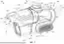


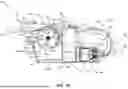


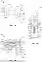


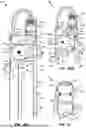


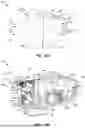


Sources:
- United States Patent and Trademark Office - verify current appl. status at the USPTO↗
Similar patent applications:
- » 20190104903
CYCLONE ASSEMBLY FOR SURFACE CLEANING APPARATUS AND A SURFACE CLEANING APPARATUS HAVING SAME - » 20180303301
Cyclone assembly for surface cleaning apparatus and a surface cleaning apparatus having same - » 20190090708
Cyclone assembly for surface cleaning apparatus and a surface cleaning apparatus having same - » 20170303757
Cyclone assembly for surface cleaning apparatus and a surface cleaning apparatus having same - » 20170303759
Cyclone assembly for surface cleaning apparatus and a surface cleaning apparatus having same - » 20180296044
SUCTION NOZZLE FOR A HARD SURFACE CLEANING APPARATUS AND HARD SURFACE CLEANING APPARATUS HAVING SUCH A SUCTION NOZZLE - » 20190059671
Cyclone assembly for surface cleaning apparatus and a surface cleaning apparatus having same - » 20170303758
Cyclone assembly for surface cleaning apparatus and a surface cleaning apparatus having same - » 20170303756
Cyclone assembly for surface cleaning apparatus and a surface cleaning apparatus having same - » 20200093338
Cyclone assembly for surface cleaning apparatus and a surface cleaning apparatus having same
Recent applications in this class:
- » 20260053316 2026-02-26
MOTOR ASSEMBLY AND SURFACE CLEANING DEVICE - » 20260053315 2026-02-26
CLEANER - » 20260041293 2026-02-12
HANDHELD SURFACE CLEANER - » 20260000258 2026-01-01
DUST COLLECTOR, VACUUM CLEANER, AND CLEANING APPARATUS - » 20260000257 2026-01-01
HAND VACUUM CLEANER - » 20250302251 2025-10-02
SUCTION APPARATUS AND SEPARATOR UNIT FOR A SUCTION APPARATUS WITH AN OBLIQUELY POSITIONED FLOW DIVERSION - » 20250275656 2025-09-04
SURFACE CLEANING APPARATUS - » 20250275655 2025-09-04
HANDHELD SURFACE CLEANER - » 20250261813 2025-08-21
SURFACE CLEANING APPARATUS - » 20250241496 2025-07-31
CYCLONIC AIR TREATMENT MEMBER AND SURFACE CLEANING APPARATUS INCLUDING THE SAME