RETRACTOR SYSTEM FOR SPINE SURGERY
US20260053486A1
2026-02-26
19/104,837
2023-09-21
Smart Summary: A retractor system is designed for spine surgery to help doctors access the spine safely. It consists of two main parts called retractor members, each with a blade and a frame. The system includes pins that can be secured into the vertebrae to hold the retractor in place. A special channel in at least one retractor member allows the pins to slide and adjust, but the channel is positioned differently from the blade. Additionally, the system can have shims with guiding grooves to assist in proper placement. 🚀 TL;DR
Abstract:
Retractor system for spine surgery comprising two retractor members (1,2) being each made of a blade (1) and a proximal part forming a frame (2), at least two pins (10) having each a distal end configured to be anchored in a vertebra, and a blocking mechanism (5) for maintaining the retractor members (1,2) at a certain distance from each other; wherein at least one retractor member (1,2) contains a channel (3) that is configured to slidably hold said pin (10); characterized by the fact that the channel (3) is oriented along a direction that differs from the blade (1) direction. The invention also relates to a retractor system that includes at least one shim (12) with guiding grooves (15) ending before the shim distal end.
Inventors:
- Morten Beyer 17 🇩🇰 Rodkaersbro, Denmark
- Lionel SIMON 4 🇫🇷 Solaize, France
- Vincent Lefauconnier 9 🇨🇭 Brent, Switzerland
Applicant:
Interested in similar patents?
Get notified when new applications in this technology area are published.
Classification:
A61B17/025 » CPC main
Surgical instruments, devices or methods, e.g. tourniquets for holding wounds open; Tractors Joint distractors
A61B17/0206 » CPC further
Surgical instruments, devices or methods, e.g. tourniquets for holding wounds open; Tractors with antagonistic arms as supports for retractor elements
A61B90/39 » CPC further
Instruments, implements or accessories specially adapted for surgery or diagnosis and not covered by any of the groups - , e.g. for luxation treatment or for protecting wound edges Markers, e.g. radio-opaque or breast lesions markers
A61F2/4611 » CPC further
Filters implantable into blood vessels; Prostheses, i.e. artificial substitutes or replacements for parts of the body; Appliances for connecting them with the body; Devices providing patency to, or preventing collapsing of, tubular structures of the body, e.g. stents; Prostheses implantable into the body; Joints; Special tools or methods for implanting or extracting artificial joints, accessories, bone grafts or substitutes, or particular adaptations therefor for insertion or extraction of endoprosthetic joints or of accessories thereof of spinal prostheses
A61B2017/0256 » CPC further
Surgical instruments, devices or methods, e.g. tourniquets for holding wounds open; Tractors; Joint distractors for the spine
A61B2090/3966 » CPC further
Instruments, implements or accessories specially adapted for surgery or diagnosis and not covered by any of the groups - , e.g. for luxation treatment or for protecting wound edges; Markers, e.g. radio-opaque or breast lesions markers Radiopaque markers visible in an X-ray image
A61B17/02 IPC
Surgical instruments, devices or methods, e.g. tourniquets for holding wounds open; Tractors
A61B90/00 IPC
Instruments, implements or accessories specially adapted for surgery or diagnosis and not covered by any of the groups - , e.g. for luxation treatment or for protecting wound edges
A61F2/46 IPC
Filters implantable into blood vessels; Prostheses, i.e. artificial substitutes or replacements for parts of the body; Appliances for connecting them with the body; Devices providing patency to, or preventing collapsing of, tubular structures of the body, e.g. stents; Prostheses implantable into the body; Joints Special tools or methods for implanting or extracting artificial joints, accessories, bone grafts or substitutes, or particular adaptations therefor
Description
FIELD OF INVENTION
The present invention generally relates to surgical retractors systems that are configured for approaching the spine with a lateral, anterior or posterior surgical technique.
BACKGROUND OF THE INVENTION
Spinal surgical retractors systems are used for retracting and maintaining soft tissues away from the surgical site to enable the surgeon to access intervertebral discs (or any other structure of the spine), for instance for removing them partially and place implants such as a cage or screws
A retractor system usually includes at least two blades having each a proximal part forming a frame, two pins having each a distal end configured to be anchored in a vertebra and a blocking mechanism for maintaining the blades at a certain distance from each other.
Retractor systems as defined above are disclosed for instance in patent documents U.S. Pat. Nos. 9,220,491 B2 and 10,470,753 B2.
In some systems each blade contains a channel that is configured to slidably hold one pin. See for instance U.S. Pat. Nos. 8,852,089 B2 and 11,426,152 B2.
In those prior art systems, the channel is oriented along a direction that is parallel to the blade direction.
Shims may also be placed between the blade edges or fixed to a blade to prevent the ingress of unwanted or sensitive biological structures, such as tissues, nerves, or vessels, into the surgical target site, as well as to prevent instruments from passing outside the surgical target site and contacting surrounding tissues or structures. Such shims are disclosed in U.S. Pat. Nos. 9,220,491 B2, 10,470,753 B2 or 8,821,396 B1.
Several disadvantages are associated with prior art systems, in particular the risk of an accidental withdrawal of the blades from the surgical site, due to the pressure imparted on the blades by the surrounding tissues. In addition, the way to expand usually from the frame structure makes it necessary to have very stiff material and a potentially bulky structure.
It is also complicated, if not impossible, to maintain the blades around the surgical site and only retrieve the shims, for instance for allowing an easier access to the surgical site.
SUMMARY OF THE INVENTION
According to the present invention, several solutions are provided to overcome the drawbacks of the prior art.
To this effect the invention provides a retractor system for spine surgery comprising two retractor members being each made of a blade and a proximal part forming a frame, at least two pins having each a distal end configured to be anchored in a vertebra, and a blocking mechanism for maintaining the blades at a certain distance from each other; wherein at least one retractor member contains a channel that is configured to slidably hold the pin; characterized by the fact that the channel is oriented along a direction that differs from the blade direction.
Preferred embodiments of the invention are defined in the claims.
BRIEF DESCRIPTION OF THE DRAWINGS
Other features, aspects and advantages of the present invention will be more fully understood when considered with respect to the following detailed description, appended claims, and accompanying drawings where:
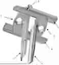
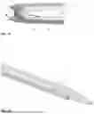
FIG. 1 represents an example of a retractor member according to the invention
FIG. 2 represents shows a pair of retractor members as illustrated in FIG. 1
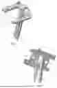
FIG. 3 shows an example of a dilator member that may be used with the retractor members of FIGS. 1 and 2
FIG. 4 shows a dilator made of two dilator members as illustrated on FIG. 3
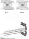
FIG. 5 shows the dilator of FIG. 4 viewed from above
FIG. 6 shows the same dilator surrounded by two retractor members (top view)
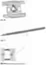
FIG. 7 is a side view of a retractor with a dilator and a pin
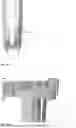
FIG. 8 shows a pin
FIG. 9 is like FIG. 7 but shows the angle between the pin and the related blade
FIG. 10 is a schematic representation of the forces acting on the blade and the pin
FIG. 11 is a top view in the blade axis
FIG. 12 is a similar view as in FIG. 11 but in the pin axis
FIG. 13 shows a retractor member with its retention ring
FIG. 14 is a perspective view of a retractor with shims
FIG. 15 represents a shim
FIG. 16 shows a top view of a retractor with shims fixed to the blades
FIG. 17 shows the distal part of a retractor with pins and a shim
FIG. 18 shows the distal part of a shim
FIG. 19 shows a similar configuration as in FIG. 17 but with a shim in a lower position
FIG. 20 shows a shim in two different positions
FIG. 21 represents a top view of a retractor system with respect to a spine portion
FIG. 22 shows a similar configuration as in FIG. 21 but in a perspective view
FIG. 23 shows another example of a retractor according to the invention (perspective top view)
FIG. 24 shows the same object as in FIG. 23, but in a perspective bottom view.
FIG. 25 shows the same object as in FIG. 23, but in a top view.
Numerical References Used in the Figures
-
- 1. Blade
- 2. Frame
- 3. Blade groove
- 4. Arm
- 5. Ratcheting system
- 6. Dilator member
- 7. K-wire channel
- 8. Guide
- 9. Dilator groove
- 10. Pin
- 11. Retention ring
- 12. Shim
- 13. Shim distal end
- 14. Guiding stop
- 15. Linear guiding groove
DETAILED DESCRIPTION OF THE INVENTION
The retractor member 1,2 shown on FIG. 1 is the main one. It is also named cranio-caudal due to its location during the operation. It is made of a blade 1 and a proximal part forming a frame 2 with two arms 4 being each located at a different height.
FIG. 2 shows the retractor basis which is made of the retractor member 1,2 of FIG. 1 and a second retractor member 1,2. The two frames 2 have a complementary shape, in such a way that when both retractor members 1,2 are joined, one arm 4 of the first frame 2 is located above one arm 4 of the second frame 2 and the other arm 4 of the first frame is located below the other arm 4 of the second frame 2.
Each frame 2 includes a ratcheting system 5 for holding the two retractor members 1,2 at a certain distance from each other.
Each blade 1 furthermore include a groove 3 that extends along the full blade length.
The groove 3 is dimensioned to slidably hold a pin 10, as defined below.
FIG. 3 represents a dilator member 6 and FIG. 4 a dilator that is made by two dilator members 6 that interlock together by means of guides 8.
The dilator is intended to expand the retractor when it is located within the soft tissues.
It has several functions, which includes the generation of an expansion from inside the retractor over the whole length of the blades 1.
The blades 1 are then reinforced and locked in the bone at the bottom with the help of a pin 10 and at the top with the frames 2.
This structure allows to manufacture the blades 1 with a material, such as plastics, that is not mechanically very strong.
As shown on FIG. 4, two dilator members 6 may be brought together to form a progressive dilator, i.e. when introduced between the retractor elements 1,2, the dilator gradually spreads the blades 1 from each other.
On its external face, each dilator member 6 contains a groove 9 which is designed to guide a pin 10. Together with its adjacent blade 1 that also contains a groove 3, a channel 3,9 is created for guiding the pin 10 within the retractor. Such a configuration provides several advantages, in particular an easier and cheaper way to manufacture the grooves (milling or injection of simple surface grooves) than a very long and narrow channel (up 200 mm long Ø3.5 hole) through the whole length of the blade.
The dilator members 6 are also designed to create a K-wire channel 7 for the initial positioning of the retractor system, around the surgical site.
The pin 10 (see FIGS. 7, 8, 9, 13) provides several functions, including to engage the bone, to lock the blades 1 at the bone level in order to prevent the blade flexion under tissues pressure, to reinforce the blades 1 as a metal frame, and it is positioned in an innovative manner that prevents the retractor to go back out of the surgical wound.
The pin 10 can be threaded or not, and can have a driving bit (hexagon, square, male, female,.) at the other end or not. Other shapes can be also contemplated for the pin other end, such as an eyelet, a bent, or an attached plastic part which can be used to retrieve the pin by pulling on it.
As shown on FIGS. 9 and 10, the channel 3,9 formed by the retractor groove 3 and the dilator groove 9 is oriented along a direction that differs from the blade direction. Consequently, when a pin 10 is located within the channel 3,9, its axis forms an angle, named “retention angle” with respect to the blade axis.
FIG. 10 schematically shows the force (vertical arrow) exerted on the blade inwardly by the surrounding soft tissues. This force has a component (left arrow, gray) that is distally oriented. This additional force prevents an accidental removal of the retractor from the surgical site.
This angle offers a second advantage as it brings the pin entry location a little backward from the internal face of the blade 1, thus making it possible to create a short retention ring 11 that maintains the pin 10 at the frame level even when the dilator is removed.
The shim 12 is a lateral blade that is intended to prevent soft tissues to enter the space between the retractor blades 1.
It has a distal end 13 designed to cut and enter the intervertebral disc, and a groove 15 to guide the shim 12 all along insertion into retractor blades 1 to avoid any deviation toward nerves backwards or vessels at the front of the patient When the shim 12 is well-placed in the disc, linear guiding is interrupted 14 and allows lateral retraction of the shim without removing or expanding the blades 1.
Alternatively, the retractor according to the invention may include only one arm per retractor member. In this case, the frame forms a U-shape. Such an alternative is illustrated on FIGS. 23, 24 and 25. In this example, there is only one ratchet on one side.
Any suitable shape and blocking mechanism for the intended purpose may be used.
The invention is of course not limited to those examples. It includes lateral, anterior and posterior retractor systems.
Same considerations apply to the number of blades and pin per retractor system.
Claims
1. Retractor system for spine surgery comprising two retractor members being each made of a blade and a proximal part forming a frame, at least two pins having each a distal end configured to be anchored in a vertebra, and a blocking mechanism for maintaining the retractor members at a certain distance from each other; wherein at least one retractor member contains a channel that is configured to slidably hold a pin; wherein the channel is oriented along a direction that differs from the blade direction.
2. System according to claim 1 wherein the channel is extending along the full blade length.
3. System according claim 1 wherein the channel is a groove.
4. System according to claim 1 wherein the channel distal part is a groove and the channel proximal part is a ring.
5. System according to claim 1 wherein each blade contains a channel that is configured to slidably hold one pin.
6. System according to claim 3 furthermore comprising a dilator for expanding the retractor, wherein said dilator is configured to be slidably mounted between the blades.
7. System according to claim 6 wherein said dilator contains at least one groove that is configured to slidably hold said pin together with the said blade groove
8. System according to claim 6 wherein said dilator is made of two members that interlock together by means of guides
9. System according to claim 6 wherein the dilator has a radio opaque distal end or includes any kind of marker and can be used to measure or control the position of a cage or implant to be placed in between vertebral bodies.
10. System according to claim 1 comprising a shim located between the blades.
11. System according to claim 1 wherein each retractor member includes two arms.
12. System according to claim 1 wherein each retractor member includes only one arm.
13. Retractor system for spine surgery comprising two blades having each a proximal part forming a frame, a blocking mechanism for maintaining the blades at a certain distance from each other, and at least one shim slidably mounted between the blades and comprising lateral linear guiding grooves wherein the guiding grooves end before the shim distal end.
14. Retractor system for spine surgery comprising two blades having each a proximal part forming a frame a blocking mechanism for maintaining the blades at a certain distance from each other, and at least one dilator for expanding the retractor, wherein said dilator is configured to be slidably mounted between the blades
15. System according to claim 14 wherein said dilator contains at least one groove that is configured to slidably hold said pin, together with the said blade groove.
16. System according to claim 14 wherein said dilator is made of two members that interlock together by means of guides.
17. System according to claim 14 wherein the dilator has a radio opaque distal end or includes any kind of marker and can be used to measure or control the position of a cage or implant to be placed in between vertebral bodies.
Images & Drawings included:


Sources:
- United States Patent and Trademark Office - verify current appl. status at the USPTO↗
Similar patent applications:
- » 20180303473
Spine surgery retractor system and related methods - » 20200305854
Spine surgery retractor system and related methods - » 20230018111
Spine surgery retractor system and related methods - » 20110201897
Retractor system for anterior cervical spine surgery - » 20220249136
Pedicle screw retractor system and method of use for spine surgery
Recent applications in this class:
- » 20260053488 2026-02-26
JOINT TENSIONING DEVICE AND METHODS OF USE THEREOF - » 20260053487 2026-02-26
TISSUE RETRACTION DEVICES, SYSTEMS, AND METHODS - » 20260033822 2026-02-05
METHODS AND DEVICES FOR ACCESSING AND RETRACTING A CAPSULE OF A JOINT - » 20260000391 2026-01-01
FORCE-INDICATING RETRACTOR DEVICE AND METHODS OF USE - » 20250387113 2025-12-25
ARTICULATED INSTRUMENTATION AND METHODS OF USING THE SAME - » 20250380940 2025-12-18
BONE DISTRACTION DEVICES AND METHODS OF USING SAME - » 20250380939 2025-12-18
LATERAL RETRACTOR SYSTEMS AND METHODS - » 20250366841 2025-12-04
Probes For Surgical Access System - » 20250366840 2025-12-04
TISSUE RETRACTOR, RETRACTION MODULES, AND ASSOCIATED METHODS - » 20250359861 2025-11-27
FORCE-INDICATING RETRACTOR DEVICE AND METHODS OF USE