Foil arrangement for a boat and a method for installing the same
US20260054801A1
2026-02-26
19/375,024
2025-10-30
Smart Summary: A hydrofoil system is designed for boats to improve their performance in water. It consists of a fastening device attached to the boat's hull below the waterline, along with two rigid elements and a main hydrofoil. The first rigid element can move in a way that allows it to connect or disconnect from the hull, while the second rigid element is angled and connects to the first. This setup allows the hydrofoil to be positioned behind the boat, enhancing lift and speed. The invention also includes a method for installing this hydrofoil arrangement on a boat. 🚀 TL;DR
Abstract:
A hydrofoil arrangement for a boat includes a fastening device, first and second rigid elements, and a main hydrofoil. The fastening device is fastened on an outside of a hull below a waterline of the resting boat. The first rigid element pivots in a first pivot plane into and out of engagement with the hull, vertical and parallel to a forward direction. The second rigid element is connected to the first rigid element and extends at an angle to the first rigid element so that a second end of the second rigid element is at a vertical distance from the hull. The main hydrofoil is fastened to the second end of the second rigid element. The first rigid element can be pivoted downwards and backwards, and thereafter upwards and further backwards, to a position where its second end is arranged stern of the hull. A method is also described.
Applicant:
Interested in similar patents?
Get notified when new applications in this technology area are published.
Classification:
B63B1/30 » CPC main
Hydrodynamic or hydrostatic features of hulls or of hydrofoils deriving additional lift from hydrodynamic forces of hydrofoil type with movable hydrofoils retracting or folding
Description
BACKGROUND
Various embodiments of the present invention relate to a foil arrangement for a boat, in particular for a motorboat. Embodiments of the invention also relate to a method for installing the same on such a boat, such as retrofitting the foil arrangement onto the hull of an existing boat.
Boats are associated with water friction when propelled, causing a drag that needs to be overwon by a propulsive force, such as from a propeller motor. Hydrodynamic pressure and wave formation around the moving hull of the boat also adds to this drag. This is true, of course, both for planning and non-planning watercrafts.
To decrease this drag, it is known to use hydrofoils. Boats being equipped with a hydrofoil will have less tolerance for shallow water depths, and the part of the hydrofoil being underwater will be prone to fouling. Also, the hydrofoil makes it problematic to transport the boat on a trailer when out of the water. Fouling on the hydrofoil will drastically reduce its lifting force and increase drag in water. Operating a boat in foiling mode also exposes the boat to the risk of running aground, with resulting damage to the hydrofoil.
Various solutions have been attempted to address these and other problems, but they all require large structural changes to the boat hull in order to install them. This is not only expensive and complicated; it also requires the boat hull to be designed in particular ways for the hydrofoil to be installable and useful.
There is hence a need for a hydrofoil solution that can be installed onto a wide variety of different hulls without having to impart more than a minimum of structural change to the hull itself. In particular, there is a need for such a hydrofoil solution that can be retrofitted to a respective existing hull of different types of boats. For instance, it may be desired to install a hydrofoil solution to various motorboats having either an outboard motor or an inboard motor, such as with a sterndrive.
SUMMARY
Various embodiments of the invention described herein relate to a hydrofoil arrangement for a boat, the boat in turn comprising a hull.
In some embodiments, the hydrofoil arrangement comprises a fastening device arranged to be fastened on an outside of the hull in a position below a waterline of the hull when the hull does not move through the water.
In some embodiments, the hydrofoil arrangement comprises a first rigid element, the first rigid element being elongated and having a first end and a second end, the first rigid element further being arranged to be pivotally connected at the first end to a pivot point arranged at a stern of the hull so that the first rigid element can pivot in a first pivot plane to a first pivot position where it is fastened to the hull by means of the fastening device as well as to a second pivot position where it is not fastened to the hull by means of the fastening device, the first pivot plane being substantially vertical and substantially parallel to a forward direction of the boat.
In some embodiments, the hydrofoil arrangement comprises a second rigid element, the second rigid element being elongated and comprising a first end and a second end, the first end of the second rigid element being connected to the second end of the first rigid element, the second rigid element being arranged to extend at an angle to the first rigid element when the first rigid element is fastened to the fastening device so that the second end of the second rigid element is at a vertical distance from the hull.
In some embodiments, the hydrofoil arrangement comprises a main hydrofoil, fastened to the second end of the second rigid element.
In some embodiments, the first rigid element can be pivoted from the first position so that its second end moves downwards and backwards, and thereafter upwards and further backwards, to a third position where its second end is arranged stern of the hull.
In some embodiments, a length of the first rigid element between its first and second ends is longer than a length of the second rigid element between its first and second ends.
In some embodiments, the second rigid element is connected to the first rigid element at a point aligned with, or ahead of, a mass center of the boat, when the first rigid element is fastened to the fastening device.
In some embodiments, the first rigid element is pivotally connected to the second rigid element.
In some embodiments, the hydrofoil arrangement further comprises a stern hydrofoil, arranged to be fastened at the stern of the hull, the stern hydrofoil preferably being smaller than the main hydrofoil.
In some embodiments, the stern hydrofoil is arranged to be mounted on a sterndrive or, an outboard motor or a motor fixture of the boat, and further arranged to be moved by a power tilt actuator of the boat.
In some embodiments, the stern hydrofoil is arranged to tilt together with a sterndrive or outboard motor under influence of the power tilt actuator.
In some embodiments, the hydrofoil arrangement has no other hydrofoils apart from the main hydrofoil and the stern hydrofoil.
In some embodiments, the hydrofoil arrangement further comprises an attack angle actuator, arranged to adjust an attack angle of the main hydrofoil, the attack angle actuator being arranged to transfer a first force along the first rigid element to a second force along the second rigid element, the second force forcing the main hydrofoil to pivot so as to set its attack angle, the attack angle actuator comprising a force transfer element at a connection between the first rigid element and the second rigid element, the force transfer element being arranged to apply the second force in reaction to the first force.
In some embodiments, the attack angle actuator is arranged to adjust the attack angle across an angle interval of at least 30°.
In some embodiments, the main hydrofoil comprises a port part and a starboard part that are individually pivotable so as to individually set an attack angle of the port part and the starboard part.
In some embodiments, the port part and the starboard part are interconnected by a flexible section, allowing the main hydrofoil to twist under torsional force.
In some embodiments, the flexible section is manufactured from spring steel or a fiber composite material, the fiber composite material possibly comprising carbon fibers, glass fibers or polymer fibers and being designed to relatively easy allow twisting of the main hydrofoil about its longitudinal axis.
In some embodiments, the port part and the starboard part are interconnected by a rotary connection, allowing the port part and the starboard part to rotate in relation to each other about a common axis being a main elongation axis of the main hydrofoil.
In some embodiments, an attack angle of the port part and an attack angle of the starboard part are individually settable using a respective attack angle actuator.
In some embodiments, the main hydrofoil has a lateral length being the same as a lateral width of the hull within ±50%.
In some embodiments, the main hydrofoil has a width, in a direction parallel to a movement direction of the boat, the width being between 8 and 50 cm, such as between 15 and 30 cm and/or a relation between the width and a lateral length of the main hydrofoil being between 1:4 and 1:20, such as between 1:8 and 1:17, such as between 1:10 and 1:15.
In some embodiments, the hydrofoil arrangement comprises two first rigid elements, the two first rigid elements being arranged to pivot backwards on either lateral side of a propeller axle of the boat.
In some embodiments, the hydrofoil arrangement comprises two second rigid elements, the two second rigid elements being connected to the main hydrofoil at different points along the main hydrofoil in relation to each other in a lateral direction of the hull, one such connection point being arranged at a port side of the hull and one such connection point being arranged at a starboard side of the hull.
In some embodiments, the two second rigid elements are arranged to extend in a laterally diverging manner in relation to each other in a vertical direction, a half-angle of divergence being between 5° and 20°.
In some embodiments, each of the two second rigid elements are arranged to extend at an angle in a vertical-lateral plane, the angle being perpendicular ±20° to a tangent to the hull at the first end of the second rigid element.
In some embodiments, the hydrofoil arrangement comprises a first locking mechanism, arranged to releasably lock the second end of the first rigid element to the fastening device.
In some embodiments, the hydrofoil arrangement comprises a second locking mechanism, arranged to releasably lock the first end of the second rigid element in a set angular orientation in relation to the fastening device and/or to the first rigid part.
In some embodiments, the second locking mechanism is arranged to be weak enough, in relation to a strength of the first locking mechanism, so as to release the second rigid element from the angular orientation instead of the first locking mechanism releasing the first rigid element from the fastening device upon a sufficiently large sternwise-directed impulse being delivered to the second rigid element.
In some embodiments, the first rigid element can be pivoted from the third position so that its second end moves upwards and forward, to a fourth position where its second end is arranged above a propeller axle of the boat.
In some embodiments, the hydrofoil arrangement comprises a propulsion position setting device, arranged to set a vertical height of a propeller axle of the boat, such as of a sterndrive or outboard motor of the boat.
In some embodiments, the hydrofoil arrangement comprises a water surface sensor, arranged to measure a distance to the water surface from above the water surface.
In some embodiments, the hydrofoil arrangement is fastened to the hull to a sternwise-facing surface, such as a transom, of the hull.
In some embodiments, the fastening device is arranged to be fastened to a bottom of the hull using an adhesive, without penetrating the hull.
In some embodiments, the second rigid element has a profile which is rectangular apart from a curved, such as semi-circular, section facing the bow of the hull when the second rigid element is in a vertical orientation.
In some embodiments, the second rigid element is connected to the main hydrofoil via a foil connecting element which is drop-shaped in a horizontal cross-section when the second rigid element is in a vertical orientation.
In some embodiments, the second rigid element passes through the foil connecting element.
In some embodiments, the first rigid element can be pivotally driven by rotation of a horizontal axle at the pivot point.
Embodiments of the invention also relate to a method for installing a hydrofoil arrangement according to any one of the preceding claims, the method comprising providing a boat having a hull; and fastening the pivot point of the hydrofoil arrangement to a stern of the hull and fastening the fastening device to a bottom of the hull.
In some embodiments, the method further comprises fastening an outboard motor to a propulsion position setting device of the hydrofoil arrangement so that the outboard motor can be raised and lowered by the propulsion position setting device.
In some embodiments, the method further comprises fastening a sterndrive to a propulsion position setting device of the hydrofoil arrangement so that the sterndrive can be raised and lowered by the propulsion position setting device; and connecting the sterndrive to a drive shaft of the boat via a universal joint.
In some embodiments, the boat is an existing boat and the installation of the hydrofoil arrangement is a retrofit of the hydrofoil arrangement.
DESCRIPTION OF DRAWINGS
In the following, exemplifying embodiments of the invention will be described with reference to the enclosed drawings, wherein:
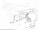
FIGS. 1 and 2 are respective perspective views of a first hydrofoil arrangement mounted on a boat, according to some embodiments;
FIG. 3 is a side view of the first hydrofoil arrangement mounted on the boat, according to some embodiments;
FIG. 4 is a back view of the first hydrofoil arrangement mounted on the boat, according to some embodiments;
FIG. 5 is a perspective view of the first hydrofoil arrangement without the boat, according to some embodiments;
FIGS. 6, 7 and 26 are respective detail perspective views of a stern fixture of the first hydrofoil arrangement, according to some embodiments;
FIGS. 8 and 9 are respective detail perspective views of a stern foil of the first hydrofoil arrangement, according to some embodiments;
FIG. 10 is a side perspective view of the first hydrofoil arrangement, but with protective covers removed so as to reveal an interior of the fastening device, according to some embodiments;
FIG. 11 is a detail back perspective view of the first hydrofoil arrangement, showing a fastening device of the first hydrofoil arrangement, according to some embodiments;
FIG. 12 is a detail top perspective view of the fastening device of the first hydrofoil arrangement, according to some embodiments;
FIG. 13 is a detail perspective view of fastening device of the first hydrofoil arrangement, according to some embodiments;
FIG. 14 is similar to FIG. 13, but with protective covers removed so as to reveal an interior of the fastening device, according to some embodiments;
FIG. 15 is similar to FIG. 14, but with a section removed so as to reveal the interior of the fastening device, according to some embodiments;
FIGS. 16 and 17 are respective detail top perspective views, with a section removed, of a main hydrofoil of a second hydrofoil arrangement, according to some embodiments;
FIG. 18 is a detail top view of the main hydrofoil of the second hydrofoil arrangement, according to some embodiments;
FIG. 19 is a detail perspective view of a flexible section of the main hydrofoil of the second hydrofoil arrangement, according to some embodiments;
FIG. 20 is a detail perspective view of a rotary connection of a third hydrofoil arrangement, according to some embodiments;
FIG. 21 corresponds to FIG. 3 but showing the first hydrofoil arrangement in a partly retracted state, according to some embodiments;
FIG. 22 corresponds to FIG. 3 but showing the first hydrofoil arrangement in a more retracted state, according to some embodiments;
FIG. 23 is a detail perspective view of a connection between a second rigid part and a main hydrofoil of the first hydrofoil arrangement, with a section removed so as to view the interior of the connection, according to some embodiments;
FIG. 24 is a control chart illustrating the operation of a control device of a hydrofoil arrangement, according to some embodiments; and
FIG. 25 is a flowchart illustrating a method, according to some embodiments.
Throughout the Figures, the same reference numerals are used to denote same or corresponding parts.
DETAILED DESCRIPTION
FIGS. 1-5 generally show a hydrofoil arrangement 100 for a boat 10, according to some embodiments. The boat 10 comprises a hull 11 having a bottom 13, a stern 15 and a bow 16. The bow 16 can comprise a transom 17. The boat 10 can also have an outboard motor 18, in turn having a propeller axle 19. As will be clear from the below, the present invention contemplates that the boat 10 can alternatively have an inboard motor in combination with either a sterndrive or a direct propeller drive from the inboard motor.
The boat 10 can furthermore have a power tilt system, in turn comprising a power tilt actuator 20.
The boat 10 can be any boat capable of foiling when propelled forward by its electric- and/or internal combustion engine. In some embodiments, the boat is a recreational boat, a transport boat or a commuter boat. In some embodiments, the boat 10 is at the most 15 meters of length.
When the boat 10 rests in the water and is not moving, it is associated with a waterline 14. The waterline 14 can be measured for a normal use case or a maximum use case in terms of a payload for the boat 10 (including cargo and passengers).
The hydrofoil arrangement 100 comprises a fastening device 101, arranged to be fastened onto an outside of the hull 11 at a position below the waterline 14. As the boat 10 foils, when driven forward by its motor and the main hydrofoil 130 (see below) is held under the hull 11, the fastening device 101 can be arranged above the waterline 14.
As used herein, the terms “foiling” and “hydrofoil” are used to describe that, when the boat 10 is propelled by its motor, such hydrofoil(s) then provide(s) a sufficient lift force to lift the hull 11 completely out of the water, so that the entire hull 11 is above the water level.
The hydrofoil arrangement 100 further comprises one or at least two first rigid elements 110, each such first rigid element 110 being elongated and having a first end 111 and an opposite second end 112. The first rigid element 110 can be manufactured from a suitable rigid material, for instance a metal material. Concretely, as the material can be, for instance, aluminum, steel or composite.
The first rigid element 110 is further arranged to be pivotally connected at its first end 111 to a pivot point 113 arranged at the stern 15 of the hull 11, so that the first rigid element 110 can pivot in a first pivot plane to a first pivot position where it is fastened to the hull 11 by means of the fastening device 101. This pivot position is illustrated in FIG. 3, and as can be seen in this FIG. 3 the first element 110 can then be arranged substantially horizontal and/or follow a contour of the bottom 13 of the hull 11, extending between the pivot point 113 and the fastening device 101.
The pivot point 113 can be fixed, such as permanently fastened, to the hull 11. For instance, the pivot point 113 can be fixedly arranged in relation to a stern fixture 160 (see below), in turn being arranged to be permanently and fixedly mounted to the hull 11.
The first rigid element 110 is further arranged to pivot, via the pivot point 113, to a second pivot position where it is not fastened to the hull 11 by means of the fastening device 101. An example of the second pivot position is shown in FIG. 21, where the first rigid element 110 has pivoted 180° backwards about the pivot point 113. Another example of the second pivot position is shown in FIG. 22, where the first rigid element 110 has pivoted 250° backwards about the pivot point 113. In the state of the system 100 shown in FIG. 22, it is also possible to raise the motor 18, or have the motor 18 in a raised position, so that the propeller axle 19 is arranged at a suitable depth in the water for conventional, non-foiling drive, such as planning or non-planning drive, of the boat 10.
The first pivot plane can be substantially or completely vertical, and can also be substantially or completely parallel to a forward direction of the boat 10.
It is understood that the hydrofoil arrangement 100 exemplified in FIGS. 1-5 and 21-22 comprises two first rigid elements 110, that are interconnected by the main hydrofoil 130 and therefore move in concert so that they are always parallel. It is, however, envisioned that the hydrofoil arrangement 100 can comprise only one first rigid element 110 (for instance centrally located in a lateral direction of the boat 10), or three or more parallel first rigid elements 110.
The hydrofoil arrangement 100 further comprises one or at least two second rigid elements 120, each such second rigid element 120 being elongated and comprising a first end 121 and an opposite second end 122. The second rigid elements 120 can also be manufactured from a suitable rigid material of the general types discussed above in relation to the first rigid elements 110, such as a metal material or composite.
The first end 121 of each second rigid element 120 is connected to the second end 112 of a corresponding first rigid element 110, such as via a common or individually provided fastening device 101. It is hence understood that each second rigid element 120 can be connected directly or indirectly to a corresponding first rigid element 120. Moreover, each first rigid element 110 can connect to one or more several second rigid elements 120, and each second rigid element 120 can connect to one or several first rigid elements 110. What is important is that the first end of each second rigid element 120 is connected, directly or indirectly, to a corresponding second end of a first rigid element 110, so that the entire second rigid element 120 moves as a result of the corresponding first rigid element pivoting about the pivot point 113 unless the second rigid element 120 simultaneously moves in relation to the pivoting first rigid element 110.
The connection between each second rigid element 120 and the corresponding first rigid element 110 can be a pivoting connection, so that the second rigid element 120 can pivot about a pivot point of the connection in question, in relation to the first rigid element 110 in question.
In this and other embodiments, the second rigid element 120 is arranged to extend at an angle 127 (see FIG. 3) to the first rigid element 110 when the first rigid element 110 is fastened to the fastening device 101. This angle 127 can be adjustable or fixed, and is measured as an angular difference between a main longitudinal direction of extension of the first rigid element 110, such as extending between the pivot point 113 and a pivot point between the rigid elements 110, 120, and a corresponding main longitudinal direction of extension of the second rigid element 120, such as extending between the pivot point between the rigid elements 110, 120 and a connection between the second rigid element 120 and the main hydrofoil 130.
More particularly, the second rigid element 120 is arranged to extend at the angle 127 so that the second end 122 of the second rigid element 120 is at a vertical distance from the hull 11. In the operating orientation illustrated in FIG. 3, in which the main hydrofoil 130 is arranged at a maximum distance from the hull 11 due to a corresponding selection of the angle 127, the vertical distance between the main hydrofoil 130 and the hull 11 can be at least 1 m. In this operating orientation, the angle 127 can be approximately 90°, such as 75°-105°, and/or the main hydrofoil 130 can be provided vertically below the fastening device 101. For instance, a vertical line originating at a pivot point of a connection between the first rigid element 110 and the corresponding second rigid element 120 can be arranged to pass through the main hydrofoil 130.
The main hydrofoil 130 is fastened to the second end 122 of the second rigid element 120.
The first rigid element 110 can be pivoted, about the pivot point 113, from the first position (FIG. 3) so that its second end 112 moves downwards and backwards, and thereafter upwards and further backwards, to a third position (FIG. 21) where its second end 112 is arranged sternwise of the hull 11. As mentioned above, the first rigid element 110 can from there be arranged to pivot further, by pivoting about pivot point 113 upwards-forwards to the more folded-in orientation shown in FIG. 22 where the entire second rigid element 120 is arranged above the waterline 14. In the orientation shown in FIG. 22, the second end 112 of each first rigid element 110 can be arranged above a propeller axle 19 of the boat 10.
This way, the hydrofoil arrangement 100 can be folded up from the water beneath the boat 10, to the position illustrated in FIG. 21 or FIG. 22, or even further, when it is not used. For instance, this means that the boat 10 can be used in its normal way, without the main hydrofoil 100, for example when navigating in shallow waters. The boat 10 can also be used for normal planning operation, without foiling, in this state. Also, the hydrofoil arrangement 100 can be folded up so that the main hydrofoil 130 is not subjected to fouling when the boat 10 is not used.
Two first rigid elements 110 of the hydrofoil arrangement 130 can be arranged to pivot backwards on opposite lateral sides of a propeller axle 10 of the boat 10 when pivoted backwards from the operating orientation illustrated in FIG. 3 to the orientation illustrated in FIG. 21 or 22. Preferably, the two first rigid elements 110 are provided at a distance from each other allowing them to pass on opposite sides of the outboard motor 18 or any sterndrive used with the boat 110. On the other hand, in some embodiments none of the first rigid elements 110 used in the hydrofoil arrangement 100 are arranged to be located laterally outside of the hull 11 at any time, but are then instead arranged to always (and preferably completely) be arranged and move beneath, behind (sternwise of) and possibly above the hull 11. Correspondingly, each second rigid element 120 can be arranged to never be located laterally outside of the hull 11 during foiling operation and folding of the hydrofoil arrangement 100.
A longitudinal length of the first rigid element 110, between its first 111 and second 112 ends, can be longer than a length of the corresponding second rigid element 120, between its first 121 and second 122 ends. This way, the entire foil-carrying part of the hydrofoil arrangement 100 can be folded together in the more fully folded-in position (FIG. 22), only occupying a minimal space when not in use.
To accomplish this, and as mentioned above, the first rigid element 110 can be pivotally connected to the second rigid element 120, such as at or even via the fastening device 101 when the first rigid element 110 is fastened to the fastening device 101. However, the pivotal connection between the first rigid element 110 and the second rigid element 120 is preferably via a separate pivot joint, such as using a bolt or other suitable pivot axle interconnecting the two rigid elements 110, 120.
The second rigid element 120 can be connected to the first rigid element 110 at a point aligned with, or slightly ahead of, such as within less than 0.5 meters of a vertical projection of, a mass center of the boat 10, when the first rigid element 110 is fastened to the fastening device 101.
Turning now to FIGS. 8 and 9, the hydrofoil arrangement 100 can further comprise a stern hydrofoil 150, arranged to be fastened at the stern 15 of the hull 11. The stern hydrofoil 150 can be smaller than the main hydrofoil 130 in terms its weight-carrying surface during foiling and/or its associated lifting force when the boat 10 moves forward in the water during foiling at a set boat 10 speed.
Generally, the stern hydrofoil 150 can be mounted on, at or near the power source of the boat 10, such as the outboard motor 18 or at an inboard-motor stern drive, or on a motor fixture of the boat 10. This means that, as illustrated in the Figures, the stern hydrofoil 150 can be arranged to move (and in particular tilt) with the outboard motor 18 or sterndrive, for instance as a result of an operation of the power tilt actuator 20. This can mean that an attack angle of the stern hydrofoil 150 can be adjustable using the power tilt actuator 20.
In the examples shown in the Figures, the stern hydrofoil 150 is not directly connected to any other part of the hydrofoil arrangement 100. Alternatively, however, the stern hydrofoil 150 can be mounted directly on, and be directly connected to the rest of, the hydrofoil arrangement 100, for instance on or to the stern fixture 160. In either case, the hydrofoil arrangement 100 can comprise a separate activator or attack angle adjustor, arranged to adjust an attack angle of the stern hydrofoil 150 independently from any power tilt actuator 20.
The stern hydrofoil 150 can comprise a drop-shaped part 151 and a fastening means 152. The drop-shaped part 151 can constitute a connection between the stern hydrofoil 150 and the motor 18. The fastening means 152 may comprise a socket for mounting the stern hydrofoil 150 onto a fin of the outboard motor 18 or of a sterndrive, such fin then being inserted into the socket and the stern hydrofoil 150 being fastened to the outboard motor 18 or sterndrive using bolts or similar.
The present inventors have concluded that the main hydrofoil 130, possibly in combination with the stern hydrofoil 150, is enough for secure and reliable foiling of the boat 10. Hence, in some embodiments the hydrofoil arrangement 100 has no other hydrofoils apart from the single main hydrofoil 130 and any used stern hydrofoil 150. In such embodiments, the single main hydrofoil 130 can have more lifting surface and/or lifting force (as explained above) than a combined lifting surface and/or lifting force of any one or several used stern hydrofoils 150.
As is perhaps best illustrated in FIGS. 10-15 and 23, the hydrofoil arrangement 100 can further comprise an attack angle actuator 140, arranged to adjust an attack angle of the main hydrofoil 130 as it is used in the operating orientation for foiling with the boat 10 moving forward in relation to the water.
The attack angle actuator 140 is then arranged to transfer a first force 145, along the first rigid element 110, to a second force 146, along the second rigid element 120, the second force 146 forcing the main hydrofoil 130 to pivot, such as in a plane perpendicular to a lateral direction of the boat 10, so as to thereby set its attack angle. The first force 145 can be predominantly horizontal, whereas the second force 146 can be predominantly vertical when the hydrofoil arrangement 100 is in its fully folded-out operating orientation illustrated in FIG. 3.
The attack angle actuator 140 can further comprise a force transfer element 143, such as a rocker, at the connection between the first rigid element 110, at its second end 112, and the second rigid element 120, at its first end 121. This force transfer element 143 is then arranged to apply the second force 146 in reaction to the first force 145.
In the embodiment examples illustrated in the Figures, the first force 145 is achieved by a linear actuator 141, such as an electric or hydraulic actuator, provided in connection to, or forming part of, the fastening device 101. In such embodiments, the actuator 141 can apply the first force 145 directly to the force transfer element 143. In other embodiments, the first force 45 can be achieved by a rotary-acting actuator, such as an electric motor with a cam mechanism, or be delivered to the force transfer element 143 via a push rod or similar from a force-applying actuator provided at the stern fixture 160.
Further according to the illustrated embodiments, the actuator applies the first force 145 to the force transfer element 143 that is in the form of a rocker, that pivots in reaction to the first force 145 being applied thereto. This pivoting in turn applies the second force 146 to a rigid push rod 144 extending along, and is axially movable in relation to, the second rigid element 120. As is illustrated in FIG. 23, the push rod 144 pushes down onto the main hydrofoil 130 at a connection between the push rod 144 and the main hydrofoil 130, as a result causing a change of the attack angle of the main hydrofoil 130. The corresponding opposite movement pattern results in case the actuator 141 moves in the opposite direction. To achieve this, the actuator 141 can be rigidly connected to the force transfer element 143 both for pulling and pushing action; the force transfer element 143 can be spring-loaded in a direction towards the actuator 141; and/or the movement of the main hydrofoil 130 through the water can force the main hydrofoil 130 in a pivot direction resulting in that the force-transfer element 143 is urged in a direction towards the actuator 141.
As is illustrated in, for instance, FIG. 14, the attack angle actuator 140 can further comprise a position sensor 142 that is arranged to measure a currently set main hydrofoil 130 attack angle, such as by indirect measurement of the currently set position of the actuator 141, the force-transfer element 143 and/or the push rod 144. In the example shown in the Figures, the position sensor 142 reads a current pivot angle of the force transfer element 143, which then corresponds, by a known relationship, to a set main hydrofoil 130 attack angle.
The main hydrofoil 130 attack angle can be arranged to be adjustable across an angle interval of at least 30°. For instance, the attack angle can be controllable from horizontal upwards across an interval of up to 10° (such as of at least 5°), and/or downwards across an interval of up to 20° (such as of at least 15°).
It is realized that each second rigid element 120, or at least two different second rigid elements 120, can be associated with a corresponding individual attack angle actuator 140, that can be arranged to operate in concert or independently of each other. In the embodiment shown in the Figures, there are two such attack angle actuators 140, a respective push rod 144 of each extending along and in connection to its own second rigid element 120.
As is illustrated in, for example, FIG. 16, the main hydrofoil 130 can comprises a port part 131 and a starboard part 132. In some embodiments, the port part 131 and the starboard part 132 can be individually pivotable so as to individually set a respective attack angle of the port part 131 and the starboard part 132. This can be used to, for instance, steer/roll the foiling boat 10 or to adjust for various operating conditions when foiling.
The individual control of these two different attack angles can be achieved by individually operating the respective attack angle actuators 140, the attack angle actuators 140 each being connected to, and independently affecting, a respective one of the port part 131 and the starboard part 132.
To achieve this, it is possible for the main hydrofoil 130 to be manufactured to have a torsional stiffness allowing it to deform (undergo torsion) as a result of different angles of attack being imparted to the port part 131 and to the starboard part 132 as a result of the control described above. This case is illustrated, for example, in FIG. 23, and can involve primarily one or several (longitudinally) central parts of the main hydrofoil 130, or the main hydrofoil 130 along its entire longitudinal length, twisting due to a torsional force being applied between the different second rigid elements 120.
In other cases, such as is illustrated in FIGS. 16, 17 and 19, the port part 131 and the starboard part 132 are interconnected by a flexible section 133, allowing the main hydrofoil 130 to twist, such as predominantly locally, under torsional force. In some embodiments, such a flexible section 133, or even a part of the main hydrofoil 130 extending between the connection points of the different second rigid elements 120 to the main hydrofoil 130, can be manufactured from a spring steel, allowing the repeated torsion and reversing of the main hydrofoil 130 without breaking. Alternatively, a fiber composite material can be used, for instance comprising carbon fibers, glass fibers or polymer fibers and being designed to relatively easy allow twisting of the main hydrofoil 130 about its longitudinal axis but at the same time be relatively stiff in terms of bending of the main hydrofoil 130.
As is illustrated in the Figures, the flexible section 133 can be associated with a local material weakening, such as a socket or recess, in the main hydrofoil 130, allowing a relatively large torsion at the point of the flexible section 133 as compared to a torsion at points at a distance from the flexible section 133 under an applied torsion force to the main hydrofoil 130.
In alternative embodiments, exemplified in FIG. 20, the port part 131 and the starboard part 132 are interconnected by a rotary connection 134 such as a journalled connection, such as having an axis 137 allowing the rotation, allowing the port part 131 and the starboard part 132 to rotate in relation to each other about the common axis formed by the main elongation axis of the main hydrofoil 130.
In yet alternative embodiments, the main hydrofoil 130 can be divided into one or more parallel sections, such sections being aligned in a vertical plane parallel to the forward direction of the boat 10, the sections together forming the main hydrofoil 130 but not being connected one to the other. In other words, in such cases the main hydrofoil 130 comprises two, or three or more, main hydrofoil sections arranged beside each other and separated by a respective distance in the lateral direction of the boat 10. Each such section can then be connected to its own second rigid element 120. Furthermore, each such section, or at least two such sections, can be individually tiltable so as to adjust its respective attack angle via a respective attack angle actuator 140.
As is illustrated in FIG. 4, the main hydrofoil 130 can have a lateral length 135, along its longitudinal direction, that is the same as a lateral maximum width 12 of the hull 11 within ±50%, or even within ±30%. In certain embodiments, the lateral length 135 roughly or substantially corresponds to the width 12. This can imply that the connection of any second rigid element 120 to the main hydrofoil 130 is arranged at a certain distance from each longitudinal end point of the main hydrofoil 130.
As the term is used here, the length 135 of the main hydrofoil 130 is the total lateral length of the main hydrofoil 130 in case the main hydrofoil is connected, or to total lateral length of all the sections of the main hydrofoil 130 in case the main hydrofoil 130 is sectioned as described above.
In some embodiments, the length 135 can be at least 1 m, such as at least 2 m. Moreover, in some embodiments the length 135 can be at the most 5 m, such as at the most 4 m.
Furthermore, the main hydrofoil 130 can have a width 136, in a direction parallel to a movement direction of the boat 10 and perpendicular to the longitudinal direction of the main hydrofoil 130, of between 10 cm and 100 cm.
As is illustrated in FIG. 11, the two second rigid elements 120 can be arranged to extend in a laterally diverging manner in relation to each other in a vertical direction when the hydrofoil arrangement 100 is completely folded out as shown in FIG. 3. In particular, a half-angle 123 of divergence between the two second rigid elements 120 can be between 5° and 20°. In other words, in the generally preferred case in which the two second rigid parts 120 are symmetric with respect to their general respective longitudinal extensions, each second rigid element 120 can extend at an angle of between 2.5° and 10° in relation to the vertical. It is understood that the direction of extension here refers to a main longitudinal direction of the second rigid element 120 in question, with the same meaning as described above.
In some embodiments, each second rigid element 120, or at least two of the second rigid elements 120, can be arranged to extend perpendicularly out from a respective connection point to the hull 11 (such as the corresponding respective fastening device 101). More particularly, each of the two second rigid elements 120 can be arranged to extend at an angle in a vertical-lateral plane, the angle being perpendicular within ±20° to a tangent to the hull 11 at the first end 121 of the second rigid element 120 in question. An example of this is, again, illustrated in FIG. 11.
Reverting back to FIGS. 14 and 15, the hydrofoil arrangement 100 can comprise a first locking mechanism 102, such as one such first locking mechanism 102 per first rigid element 110, arranged to releasably lock the second end 112 of the first rigid element 110 to the fastening device 101 so that the first rigid element 110 when locked cannot pivot about the pivot point 113. More particularly, the first rigid element 110 can, when locked by the fist locking mechanism 102, be completely fixed and immobile in relation to the hull 11. The first locking mechanism 102 can comprise an actuator 107 arranged to impart activating and inactivating pivoting movement to a pivot element 104 that in turn correspondingly engages with or disengages from a hole, recess or edge 103 of the fastening device 101 so as to lock or unlock the first rigid element 110 in question. The hole, recess or edge 103 can be formed in a fastening plate 105 (see below), such as in or through a fastening ridge 106 of such a fastening plate 105.
In some embodiments, the hydrofoil arrangement 100 comprises two first locking mechanisms 102, locking a respective one of two different first rigid elements 110 to the hull 11 at a respective location where a lateral distance between these two locations is at least 1 meter, so that the hydrofoil arrangement 100 more readily can absorb lateral forces occurring during foiling operation when the boat 10 moves forward. The two first rigid elements 110 are then preferably fastened to the hull at a symmetric respective location about a vertical symmetry plane splitting the hull 11 in two equal lateral parts.
The hydrofoil arrangement 100 can also comprise a second locking mechanism 114, such as one such second locking mechanism 114 per second rigid element 120. Each second locking mechanism 114 is preferably independently operating in relation to all instances of the first locking mechanism 102. Such second locking mechanism 114 can be arranged to releasably lock the first end 121 of the second rigid element 120 in a set angular/pivot orientation in relation to the fastening device 101 and/or to the first rigid part 110. The second locking mechanism 114 can comprise an actuator 117 arranged to impart activating and inactivating translational movement to a locking element in the form of a slider 116 that in turn correspondingly engages with or disengages from a hole, recess or edge 115 of the fastening device 101 so as to lock or unlock the second rigid element 120 in question. The hole, recess or edge 115 can be formed in the second rigid element 120.
In some embodiments, for each pair of first rigid element 110 and second rigid element 120, the second locking mechanism 114 is arranged to be weak enough, in relation to a strength of the first locking mechanism 102, so as to release the second rigid element 120 from a locked state to an unlocked state instead of the first locking mechanism 102 releasing the first rigid element 110 from a locked state to an unlocked state upon a sufficiently large sternwise-directed impulse being delivered to the second rigid element 120. Such impulse may be the result of the main hydrofoil 130 running into an obstacle underwater during foiling operation when the boat 10 moves forward. By the second locking mechanism 114 being designed to fail first in this way, the second rigid elements 120, and with them also the main hydrofoil 130, will as a result of the impulse be folded backwards-upwards, instead of the first rigid elements 110 coming loose from the fastening device 101. This, in turn, limits the damage to the hydrofoil arrangement 100 and boat hull 10 under such circumstances.
Turning to FIGS. 6 and 7, the hydrofoil arrangement 100 can comprise a stern fixture 160, that can be rigidly fastened to the stern 15 of the boat 10, such as to the transom 17. The stern fixture 160 can comprise a propulsion position setting device 161, arranged to set a vertical height of a propeller axle 19 of the boat 10, such as the propeller axle 19 of a sterndrive or of the outboard motor 18. As is illustrated in FIG. 6 and 7, the propulsion position setting device 161 can comprise an actuator 162, such as a hydraulic piston, arranged to control the height of the propeller axle 19 via link arms 167 connecting a fixed end 165 of the stern fixture 160, in turn being fixedly connected to the boat 10, to a movable end 166 of the stern fixture 160, in turn being connected to the propeller axle 19 so as to define the height of the propeller axle 19. For instance, the outboard motor 18 or the sterndrive can be mounted on the movable end 166 of the stern fixture 160 so as to move with the stern fixture 160. A fixture part 168, such as a resilient piece of material, such as rubber, plastic, wood or other vibration-dampening material, can be provided for connecting the motor 118 to the rest of the stern fixture 160. A per se conventional universal joint can be used to connect the propeller axle coming out from an inboard motor of the boat 10 to the movable end 166. In the case of an outboard motor 18, no such connection is necessary. The stern fixture 160 can also comprise a drive height sensor 169, reading the current vertical position of the propeller axle 19.
As mentioned, the hydrofoil arrangement 100, such as the stern fixture 160, can be fastened to the hull 11 to a sternwise-facing surface, such as the transom 17, of the hull 11.
As is illustrated in, for instance, FIGS. 6 and 7, the one or several first rigid elements 110 can be arranged to be pivoted about the pivot point 113 using a hydrofoil engagement and pivot actuator 163, such as a hydraulic mechanism or an electric motor, arranged to turn a horizontal axle 164 that is connected for imparting a pivoting movement to at least one, such as each, of the one or several first rigid elements 110. Hence, the actuator 163 controls the pivoting movement of the first rigid elements 110 between the orientations illustrated in FIGS. 3 and 21, and possibly also that illustrated in FIG. 22. The axle 164, which is understood to define the pivot point 113, and/or the actuator 163, can be rigidly fastened to, such as comprised in, the stern fixture 160.
Turning to FIGS. 5, 11 and 12, the fastening device 101 can comprise a plate 105, such as a metal plate. The plate 105 can be arranged to be fastened to the outside of the hull 11 using a suitable adhesive. In order to distribute occurring forces, the plate 105 can extend over an area of at least 0.5 meters by 0.5 meters across the surface of the hull 11, but may comprise holes or sockets where no adhesion is present. The plates 105 can comprise one or several ridges 106 extending in the direction of forward movement of the boat 10, so that each first rigid element 110 fastens (such as locks, for instance via the first locking mechanism 102 described above) to a respective such ridge 106. For instance, each ridge 106 can comprise a respective through hole 103 arranged to receive and engage with a locking part, such as actuator 104, of the first rigid element 110 in question. This provides for a simple yet sturdy construction.
In general, the fastening device 101 can be arranged to be fastened to the bottom 13 of the hull 11 using a suitable adhesive, without penetrating the hull 11.
Further generally, in some embodiments the entire hydrofoil arrangement 100 is fastened to the boat 10 only at the fastening device 101 (and preferably only via one single plate 105) and at the stern fixture 160. The stern fixture 160 can be fixed to the hull 11 using an adhesive also, but it is preferred to mount the stern fixture 160 using a conventional bolt engagement or similar, above the waterline 14. This way, the hydrofoil arrangement 100 can be mounted onto the boat 10 without having to puncture the hull 11 below the waterline 14 and with a minimum of work. The resulting construction is simple yet sturdy and functional.
As can be seen in FIGS. 16-18, the second rigid element 120 can have a rounded front side and a rectangular, sharp back side as seen in a horizontal cross-section. One part of the second rigid element 120, when the hydrofoil arrangement 100 is in its fully folded-out orientation shown in FIG. 3, the boat 10 foils and the hull 11 hence is located above the water surface, is in contact with the air above the water surface. Due to this air contact, an ejector effect causes air to be sucked down along the back side of the second rigid element 120, into the water along the second rigid element 120 in question. This in turn causes water resistance to be smaller as compared to the situation without any such air flow downwards. The alternative would be to manufacture the second rigid element 120 with a drop-shaped profile, which is more complex.
In general, the second rigid element 120 can have a profile which is rectangular apart 124 from a curved, such as semi-circular, section 125 facing the bow 16 of the hull 11 when the second rigid element 120 is in a vertical orientation.
On the other hand, the second rigid element 120 can be connected to the main hydrofoil 130 via a respective foil connecting element 126 that in turn can have a drop shape in a horizontal cross-section when the second rigid element 120 is in a vertical orientation. Such drop-shaped connecting element 126 stops the air mixture from occurring close to the main hydrofoil 130, which would decrease its lifting force in the water.
As is illustrated in FIGS. 16-18, the second rigid element 120 can then pass through a through hole in the foil connecting element 126. In this and in other cases, the foil connecting element 126 can abut directly to the main hydrofoil 130.
Turning to FIG. 1, the hydrofoil arrangement 100 can further comprise a water surface sensor 170, being arranged to measure a distance to the water surface from above the water surface. The sensor 170 can comprise a LIDAR, a radar, a sonic distance sensor, a stereoscopic camera pair or any other suitable sensor arranged to measure a current distance, such as a vertical distance, from a measurement point on the boat 10 to the water surface; and/or to measure a shape of the water surface, such as a choppiness, a wave height, a wave length or a wave travel direction of the water surface.
The hydrofoil arrangement 100 can also comprise a control device 180, such as a per se conventional general-purpose computing device having installed thereon computer software arranged to control the operation of the hydrofoil arrangement 100. The control device 180 is connected to, and arranged to accept data input from, any or all of the available sensors, including the ones described herein, such as including the position sensor 142 and the water surface sensor 170. The control device 180 can also be connected to, and arranged to accept data input from, additional internal or external sensors, such as a current velocity sensor (for instance a GPS sensor or a conventional log), an accelerometer and/or an inclination sensor, such as a gyro, arranged to measure current yaw, roll and/or pitch of the boat 10. The control device 180 is further connected to, and arranged to control, all actuators, such as including one or several of the power tilt actuator, actuator 107, actuator 117, actuator 141, actuator 162 and actuator 162. Such control will then be in reaction to control logic produced by the software based on the sensor input. The control device 180 can also comprise or be connected to, and control, any hydraulic system controlling the actuators via hydraulic pressure.
Hence, the control device 180, by controlling the actuators, can cause the hydrofoil arrangement 100 to pivot down under water, such as from the position shown in FIG. 21 or that shown in FIG. 22, to the position shown in FIG. 3, and to be locked there by activating the first locking mechanism 102 and the second locking mechanism 114. The first locking mechanism 114 can also be arranged to be automatically activated for locking as the first rigid element 110 is pressed upwards against the fastening device 101 as a result of the pivoting down. The second locking mechanism 114 can be arranged to be automatically activated for locking as the second rigid element 120 is pivoted into its operating pivot orientation in relation to its corresponding first rigid element 110, which may take place manually, above water.
Then, the control device 180 can be used to, during operation of the boat 10 moving forward, control the propulsion position setting device 161 to a desired height, the main hydrofoil 130 attack angles, and the stern foil 150 attack angles so as to achieve an efficient and pleasant drive of the boat 10. It is understood that such operation of the boat 10 normally involves the boat 10 foiling, in other words the hull 11 of the boat 10 being lifted by the foils 130, 150 so that it is located entirely above water when the boat 10 moves forward. In order to drive the boat 10 forward, the propulsion position setting device 161 then needs to lower the propeller axle 19 correspondingly, so that the propeller drives the boat 10 under water. This height control of the propeller axle 19 can also be automatically controlled by the control device 180, as described herein.
When the boat 10 comes to a stop, or stops foiling, the control device 180 can again be arranged to fold up the hydrofoil arrangement 100, by deactivating the actuator 107; pivoting the first rigid elements 110 backwards by activating the actuator 163; and possibly deactivating the actuator 117. The control device 180 can also raise the propulsion 18 back to a height more suited for non-foiling operation of the boat 10.
The pivotal connection between the second rigid element 120 and the first rigid element 110 can also be arranged with an controllable actuator, so that the control device 180 can control the folding in and out of the second rigid element 120 in relation to the first rigid element 110, such as when moving between the orientations shown in FIGS. 21 and 22.
The control device 180 can also comprise, or be arranged to communicate with, a user interface, such as an interactive and/or graphical user interface, such interface being arranged to allow the user to input control information and/or to view current operating status information. The user interface can comprise a per se conventional physical interface, such as a touchscreen, or be embodied in the form of an app installed onto a general-purpose mobile device such as a conventional smartphone being in wireless digital communication with the control device 180, or similar. The control device 180 can also be arranged to connect to peripheral systems, such as a driving control system of the boat 10, so that the control device 180 can read current operating status information (such as velocity, heading or fuel resources) from the driving control system, and/or so that the control device 180 can control the driving control system (such as by increasing or decreasing throttle).
FIG. 24 is a control chart illustrating possible ways for the control device 180 to control the operation of the boat 10 during foiling and at start of foiling mode.
Boxes 1.1 – 1.6 together constitute a closed loop cascade regulator for the angle of attack of the main hydrofoil 130 and/or of the stern hydrofoil 150. An inner regulator loop controls lifting force demand for each hydrofoil 130, 150 in question, which is measured as flight height of the boat 10 (distance to the water surface). The outer control loop controls the angle of attack as a function of a boat 10 speed that corresponds to the lifting force available.
In box 1.1, the height sensor data is read, and the reading can be band-pass filtered for signal shaping.
In box 1.2, the read height sensor value is diagnosed, using a rationality check to see if the read height value can be trusted or if it should be disregarded as an outlier or false read.
In box 1.3, the read height value is evaluated and processed, so as to determine a desired flight height of the boat 10.
In box 1.4, a total desired lifting force is calculated from the total payload of the boat 10 and the flight height decision; decision to maintain, lower or increase flight height.
Box 1.5 is a PID regulator, arranged to determine a desired total lift force for the boat 10.
In box 1.6, the total lifting force is split up to each respective available controllable foil lifting surface, such as the port part 131, the starboard part 132 and the stern hydrofoil 150. For each individually controlled such foil surface, a desired lifting force is calculated, using a PID regulator, as a corresponding desired foil angle as a function of current boat 10 speed. The PID regulator is then controlling, in a closed loop, each individual one of the angles of attack.
Boxes 2.1 – 2.3 together constitute a current boat 10 load estimator.
In box 2.1, a most recent or accurate known current payload value (weight) for the boat 10 is input, it can for instance be stored by the control device 180 from the last operation of the boat 180 when payload adaptation was performed.
In box 2.2, an adaptation at start of flight is performed and/or continuously updated: The lift force generated from the available hydrofoils as a function of speed and angle of attack are known. The starting weight of the boat 10 is, however, generally unknown. By setting each of the hydrofoils at a known angle of attack and then increase the boat 10 speed (as detected via information from box 3.2) until the hull 11 lifts off from water (as detected via information from box 1.1), the total lifting force generated by the hydrofoils is thereby known and can be translated into a current corresponding total weight of the boat 10. The force and/or weight is/are then stored and used as the payload input. The payload value is then used to increase accuracy and feed forward values to the PID regulators. If any sensor error occurs during flight, the total boat 10 weight needs to be known for open loop control (to increase safety).
In box 2.3, the calculated boat 10 weight is diagnosed so that outlier values and misreads can be ignored or handled in a suitable manner. Then, the boat 10 weight is fed to box 1.4.
Boxes 3.1 – 3.3 relate to the processing of detected boat 10 speed.
In box 3.1, the boat 10 velocity is measured, such as via a GPS sensor or a pressure sensor (stagnation pressure in the water). The boat 10 velocity can also be automatically received via CAN bus from engine or other on-board devices of the boat 10.
In box 3.2, the velocity value is diagnosed to check for outliers and unreasonable readings. The verified value is fed to box 2.2 for use when calculating the current payload/weight of the boat 10.
In box 3.3, the available lifting force as a function of the boat 10 speed and angle of attack for the foil surfaces is determined. This box can also include a slow adaptation for foil degradation, which is determined over time and stored. The result is fed back to box 2.2 and fed forward to box 1.5 for use as input to the PID regulator in box 1.5.
Boxes 4.1 and 4.2 relate to the steering angle.
Hence, in box 4.1, the current steering angle is read, such as from a sensor at the engine or steering column or from the boat 10 control system.
In box 4.2, the read sensor value is diagnosed in a way corresponding to boxes 1.2, 2.3 and 3.2. The output is fed forward to boxes 5.3 and 1.6, for use as input to the respective PID regulators therein.
Boxes 5.1 – 5.3 relate to the hull 11 angle.
In box 5.1, the hull 11 angle, such as longitude and lateral angles, are measured with a corresponding sensor, such as a gyro as described above.
In box 5.2, a sensor value diagnostic is performed, as described above.
In box 5.3, a PID regulation is performed, based on the input longitudinal and lateral boat 10 angles, as well as the current steering signal, wherein desired lateral angles are related to steering angle input. The longitude angle is kept horizontal at boat 10 flight.
Boxes 6.1 and 6.2 relate to foil angles.
In box 6.1, the current foil attack angle(s) are measured, such as using sensor(s) 142 as described above. The sensors can be integrated or separate from the foil actuators.
In box 6.2, the sensed foil attack angle value(s) is/are diagnosed as described above. At startup, the last known previous value can be used as a starting value. The value is fed forward to box 3.3, to be used as an input to the PID regulator in that box.
FIG. 25 illustrates a method for installing a hydrofoil arrangement 100 of the presently described type.
In a first step, the method starts.
In a subsequent step, the boat 10 is provided, having the hull 11.
In a subsequent step, the pivot point 113 is fastened to the stern 15 of the hull 11, such as to the transom 17. This fastening can be indirect, by the stern fixture 160 being fastened to the hull 11 as described above, the pivot point 113 in turn being connected to, or form part of, the stern fixture 160. The fastening can be performed using bolts or similar, above the waterline 14.
Also in this step, the fastening device 101 is fastened to the bottom 13 of the hull 11 as described above. This can comprise fastening the plate 105 to the hull 11 surface, using a suitable adhesive. It is preferred that this step is performed without taking any holes through the hull 11 below the waterline 14. It is also preferred that no additional fastening points to the hull 11, apart from those of the fastening device 101 and the stern fixture 160, are provided for the hydrofoil arrangement 100.
The method can also comprise the step of fastening the outboard motor 18 to the propulsion position setting device 161 of the hydrofoil arrangement 100 so that the outboard motor 18 can be raised and lowered by the propulsion position setting device 161. As described above, this can involve fastening the outboard motor 18 to the fixture part 168 of the movable end 166 of the stern fixture 160. The outboard motor 18 can also be connected to the boat 10 control system, fuel supply system, and similar, using per se conventional cabling and pipework.
Alternatively, the method can comprise fastening a sterndrive to the propulsion position setting device 161, so that the sterndrive can be raised and lowered by the propulsion position setting device 161. Then, the sterndrive is also connected to a drive shaft of the boat 10, such as via a universal joint as described above. Of course, relevant cabling and/or pipework can also be connected to the boat 10 control system.
As mentioned, the boat 10 can also have a propeller axle 19 directly arriving from an inboard motor. In this case, the method can also comprise connecting this axle 19 to a propeller axle of the stern fixture 160, such as using a conventional universal joint, and to fasten a propeller to the axle of the stern fixture 160.
The method can also comprise a step in which the control device 180 is connected for power and/or communication to the boat 10 control system and/or battery, using per se conventional and suitable cabling.
In a subsequent step, the method ends.
As mentioned above, the present invention is particularly (but not exclusively) useful for retrofits of existing boats 10. Hence, in some embodiments the boat 10 is an existing boat 10 and the installation of the hydrofoil arrangement 100 is a retrofit of the hydrofoil arrangement 100 onto the boat 10.
Above, preferred embodiments have been described. However, it is apparent to the skilled person that many modifications can be made to the disclosed embodiments without departing from the basic idea of the invention.
For instance, the hydrofoil arrangement 100 can have additional features in addition to ones described herein, and be designed in many different ways as long as the principles described herein are used.
Generally, some or all of the structurally load-carrying parts of the hydrofoil arrangement 100 can be manufactured from relatively simple metal parts, such as aluminum profiles or from stainless steel. Also, composite materials can be used to manufacture the parts, such as carbon- or glass-fiber.
All that is described in relation to the hydrofoil arrangement is equally applicable to the method and vice versa.
Hence, the invention is not limited to the described embodiments, but can be varied within the scope of the enclosed claims.
Claims
1. A hydrofoil arrangement for a boat comprising a hull, the hydrofoil arrangement comprising:
a fastening device arranged to be fastened on an outside of the hull in a position below a waterline of the hull when the hull does not move through the water;
a pivot point arranged at a stern of the hull;
a first rigid element, the first rigid element being elongated and having a first end and a second end, the first rigid element further being arranged to be pivotally connected at the first end to the pivot point so that the first rigid element can pivot in a first pivot plane to a first pivot position where the first rigid element is fastened to the hull by means of the fastening device as well as to a second pivot position where the first rigid element is not fastened to the hull by means of the fastening device, the first pivot plane being substantially vertical and substantially parallel to a forward direction of the boat;
a second rigid element, the second rigid element being elongated and comprising a first end and a second end, the first end of the second rigid element being connected to the second end of the first rigid element, the second rigid element being arranged to extend at an angle to the first rigid element when the first rigid element is fastened to the fastening device so that the second end of the second rigid element is at a vertical distance from the hull; and
a main hydrofoil, fastened to the second end of the second rigid element,
wherein the first rigid element can be pivoted from the first position so that its second end moves downwards and backwards, and thereafter upwards and further backwards, to a third position where its second end is arranged stern of the hull.
2. The hydrofoil arrangement of claim 1, wherein a length of the first rigid element between its first and second ends is longer than a length of the second rigid element between its first and second ends.
3. The hydrofoil arrangement of claim 1, wherein the second rigid element is connected to the first rigid element at a point aligned with, or ahead of, a mass center of the boat, when the first rigid element is fastened to the fastening device.
4. The hydrofoil arrangement of claim 1, wherein the first rigid element is pivotally connected to the second rigid element.
5. The hydrofoil arrangement of claim 1, further comprising:
a stern hydrofoil, arranged to be fastened at the stern of the hull, the stern hydrofoil preferably being smaller than the main hydrofoil.
6. The hydrofoil arrangement of claim 1, wherein the hydrofoil arrangement has no other hydrofoils apart from the main hydrofoil and the stern hydrofoil.
7. The hydrofoil arrangement of claim 1, wherein the hydrofoil arrangement further comprises an attack angle actuator, arranged to adjust an attack angle of the main hydrofoil, the attack angle actuator being arranged to transfer a first force along the first rigid element to a second force along the second rigid element, the second force forcing the main hydrofoil to pivot so as to set its attack angle, the attack angle actuator comprising a force transfer element at a connection between the first rigid element and the second rigid element, the force transfer element being arranged to apply the second force in reaction to the first force.
8. The hydrofoil arrangement of claim 1, wherein the main hydrofoil comprises a port part and a starboard part that are individually pivotable to individually set an attack angle of the port part and the starboard part.
9. The hydrofoil arrangement of claim 8, wherein the port part and the starboard part are interconnected by a flexible section, allowing the main hydrofoil to twist under torsional force.
10. The hydrofoil arrangement of claim 1, wherein the main hydrofoil has a lateral length being the same as a lateral width of the hull within ±50%.
11. The hydrofoil arrangement of claim 1, further comprising:
two first rigid elements, the two first rigid elements being arranged to pivot backwards on either lateral side of a propeller axle of the boat.
12. The hydrofoil arrangement of claim 1, further comprising:
two second rigid elements, the two second rigid elements being connected to the main hydrofoil at different points along the main hydrofoil in relation to each other in a lateral direction of the hull, one such connection point being arranged at a port side of the hull and one such connection point being arranged at a starboard side of the hull.
13. The hydrofoil arrangement of claim 1, further comprising:
a first locking mechanism, arranged to releasably lock the second end of the first rigid element to the fastening device; and
a second locking mechanism, arranged to releasably lock the first end of the second rigid element in a set angular orientation in relation to the fastening device and/or to the first rigid element.
14. The hydrofoil arrangement of claim 1, wherein the first rigid element is pivotable from the third position so that the second end of the first rigid element moves upwards and forward, to a fourth position where the second end of the first rigid element is arranged above a propeller axle of the boat.
15. The hydrofoil arrangement of claim 1, further comprising:
a propulsion position setting device, arranged to set a vertical height of a propeller axle of the boat, such as a sterndrive or outboard motor of the boat.
16. The hydrofoil arrangement of claim 1, wherein the hydrofoil arrangement is fastened to the hull to a sternwise-facing surface, of the hull.
17. A method for installing a hydrofoil arrangement according to claim 1, the method comprising:
providing a boat having a hull; and
fastening the pivot point of the hydrofoil arrangement to a stern of the hull and fastening the fastening device to a bottom of the hull.
18. The method of claim 17, further comprising:
fastening an outboard motor to a propulsion position setting device of the hydrofoil arrangement so that the outboard motor can be raised and lowered by the propulsion position setting device.
19. The method of claim 17, further comprising:
fastening a sterndrive to a propulsion position setting device of the hydrofoil arrangement so that the sterndrive can be raised and lowered by the propulsion position setting device; and
connecting the sterndrive to a drive shaft of the boat via a universal joint.
20. The method of claim 17, wherein the boat is an existing boat and the installation of the hydrofoil arrangement is a retrofit of the hydrofoil arrangement.
Images & Drawings included:


Sources:
- United States Patent and Trademark Office - verify current appl. status at the USPTO↗
Recent applications in this class:
- » 20250296657 2025-09-25
HULL UNIT WITH A HYDROFOIL SYSTEM AND MARINE VESSEL - » 20250171110 2025-05-29
Boat Hull Stabiliser Fin Deployment System - » 20250074546 2025-03-06
ELECTRIC-POWERED BOAT WITH RETRACTABLE HYDROFOIL - » 20240300620 2024-09-12
RETRACTABLE HYDROFOIL SYSTEM FOR MULTI-HULL VESSEL - » 20240278874 2024-08-22
FOLDABLE HYDROFOIL FOR BOATS - » 20240217623 2024-07-04
Hydrofoil with variable lift and drag for a watercraft - » 20240059373 2024-02-22
VARIABLE USE PONTOON BOAT SYSTEM AND METHOD - » 20230382496 2023-11-30
RETRACTABLE LIFT-PROPULSION SYSTEM FOR A WATERCRAFT AND WATERCRAFT HAVING SAME - » 20230033965 2023-02-02
BOAT WITH HYDROFOILS - » 20230002007 2023-01-05
HULL UNIT WITH A HYDROFOIL SYSTEM AND MARINE VESSEL