METHODS FOR OPERATING AN ICE MAKER APPLIANCE
US20260071802A1
2026-03-12
18/829,535
2024-09-10
Smart Summary: An ice maker has a special mold that fills with water to create ice pieces. Once the ice is formed, the mold releases the ice into a storage bin located below it. This storage bin can hold many ice pieces for later use. A sensor measures the temperature inside the storage bin to help monitor the ice. A controller uses this temperature data to check if the storage bin is full of ice. 🚀 TL;DR
Abstract:
An ice maker appliance includes a mold body with a mold cavity defined within. The mold cavity is configured to receive a fill of liquid water and form an ice piece within. The mold body is configured to release the ice piece after it has been formed. Moreover, the ice maker appliance includes an ice storage bin configured to hold a plurality of ice pieces within for retrieval. The ice storage bin is positioned below the mold body to capture the released ice piece within. Additionally, the ice maker appliance includes a non-contact-based sensing device configured to generate data indicative of a temperature within the ice storage bin. Furthermore, the ice maker appliance includes a controller operatively coupled to the non-contact-based sensing device. The controller is configured to determine whether the ice storage bin is full of ice pieces based on the data generated by the non-contact-based sensing device.
Inventors:
- Vineeth Vijayan 45 🇺🇸 Louisville, KY, United States
- Robert Alan Sellers 6 🇺🇸 Louisville, KY, United States
Applicant:
Interested in similar patents?
Get notified when new applications in this technology area are published.
Classification:
F25C5/22 » CPC main
Working or handling ice; Distributing ice particularly adapted for household refrigerators
F25C1/25 » CPC further
Producing ice; Construction of moulds; Filling devices for moulds Filling devices for moulds
F25C2600/04 » CPC further
Control issues Control means
F25C2700/02 » CPC further
Sensing or detecting of parameters; Sensors therefor Level of ice
F25C5/20 IPC
Working or handling ice Distributing ice
Description
FIELD OF THE INVENTION
The present subject matter relates generally to ice maker appliances, and in particular to methods for operating such appliances.
BACKGROUND OF THE INVENTION
Certain refrigerator appliances include an ice maker. An ice maker may also be a stand-alone appliance designed for use in commercial and/or residential kitchens. To produce ice, liquid water is directed to the ice maker and frozen. For example, certain ice makers include a mold cavity for receiving liquid water. After ice is formed in the mold cavity, it may be harvested from the mold cavity and stored within an ice bin or bucket within the refrigerator appliance.
However, conventional ice maker appliances experience issues with continuous production and release of ice pieces into the ice storage bin after the ice storage bin is already full of ice. Over accumulation of ice within the ice storage bin may require the ice to be manually removed before ice can be dispensed from the appliance.
Accordingly, improved methods for operating an ice maker appliance would be desirable. More particularly, methods for operating an ice maker appliance based on an ice fill level within the ice maker appliance would be particularly beneficial.
BRIEF DESCRIPTION OF THE INVENTION
Aspects and advantages of the invention will be set forth in part in the following description, or may be apparent from the description, or may be learned through practice of the invention.
According to an exemplary embodiment, an ice maker appliance is provided. The ice maker appliance defines a vertical direction, a lateral direction, and a transverse direction. The ice maker appliance includes a mold body. A mold cavity is defined within the mold body. Additionally, the mold cavity is configured to receive a fill of liquid water and form an ice piece therein. Furthermore, the mold body is configured to release the ice piece therefrom after the ice has been formed. Additionally, the ice maker appliance includes an ice storage bin. The ice storage bin is configured to hold a plurality of ice pieces therein for retrieval therefrom. Furthermore, the ice storage bin is positioned below the mold body to capture the released ice piece therein. Moreover, the ice maker appliance includes a non-contact-based sensing device configured to generate data indicative of a temperature within the ice storage bin. Additionally, the ice maker appliance includes a controller operatively coupled to the non-contact-based sensing device. The controller is configured to determine whether the ice storage bin is full of ice pieces based on the data generated by the non-contact-based sensing device.
According to another exemplary embodiment, a method for operating an ice maker appliance is provided. The method includes directing, with a controller, liquid water into a mold cavity of a mold body of the ice maker appliance. Moreover, the method includes receiving, with the controller, non-contact-based sensing device data indicative of a temperature within an ice storage bin of the ice maker appliance. The ice storage bin is configured to capture ice pieces released from the mold cavity. Additionally, the method includes determining, with the controller, an ice level within the ice storage bin based on the received non-contact-based sensing device data. Furthermore, the method includes initiating, with the controller, a control action associated with the ice maker appliance based on the determined ice level within the ice storage bin.
According to another exemplary embodiment, a method for operating an ice maker appliance is provided. The method includes directing, with a controller, liquid water into a mold cavity of a mold body of the ice maker appliance. Moreover, the method includes receiving, with the controller, non-contact-based sensing device data indicative of a temperature within an ice storage bin of the ice maker appliance. The ice storage bin is configured to capture ice pieces released from the mold cavity. Additionally, the method includes determining, with the controller, whether the ice storage bin is full of the ice pieces based on the received non-contact-based sensing device data. Furthermore, the method includes initiating, with the controller, a control action associated with the ice maker appliance based on determining that the ice storage bin is full of the ice pieces.
These and other features, aspects and advantages of the present invention will become better understood with reference to the following description and appended claims. The accompanying drawings, which are incorporated in and constitute a part of this specification, illustrate embodiments of the invention and, together with the description, serve to explain the principles of the invention.
BRIEF DESCRIPTION OF THE DRAWINGS
A full and enabling disclosure of the present invention, including the best mode thereof, directed to one of ordinary skill in the art, is set forth in the specification, which makes reference to the appended figures.
FIG. 1 provides a perspective view of a refrigerator appliance according to an exemplary embodiment of the present subject matter.
FIG. 2 provides a perspective view of the exemplary refrigerator appliance of FIG. 1, with the doors of the fresh food chamber shown in an open position.
FIG. 3 provides an interior perspective view of a dispenser door of the exemplary refrigerator appliance of FIG. 1.
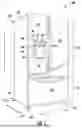
FIG. 4 provides an interior elevation view of the door of FIG. 3 with an access door of the door shown in an open position.
FIG. 5 provides a perspective view of an exemplary ice maker disposed in an icebox in accordance with one or more embodiments of the present disclosure.
FIG. 6 provides another perspective view of the exemplary ice maker of FIG. 5.
FIG. 7 provides a schematic illustration of components of an ice maker appliance in accordance with one or more embodiments of the present disclosure.
FIG. 8 provides a flow chart illustrating an exemplary method for operating an ice maker appliance in accordance with one or more embodiments of the present subject matter.
FIG. 9 provides a flow chart illustrating another exemplary method for operating an ice maker appliance in accordance with one or more embodiments of the present subject matter.
Repeat use of reference characters in the present specification and drawings is intended to represent the same or analogous features or elements of the present invention.
DETAILED DESCRIPTION
Reference now will be made in detail to embodiments of the invention, one or more examples of which are illustrated in the drawings. The word “exemplary” is used herein to mean “serving as an example, instance, or illustration.” In addition, references to “an embodiment” or “one embodiment” does not necessarily refer to the same embodiment, although it may. Any implementation described herein as “exemplary” or “an embodiment” is not necessarily to be construed as preferred or advantageous over other implementations. Moreover, each example is provided by way of explanation of the invention, not limitation of the invention. In fact, it will be apparent to those skilled in the art that various modifications and variations can be made in the present invention without departing from the scope of the invention. For instance, features illustrated or described as part of one embodiment can be used with another embodiment to yield a still further embodiment. Thus, it is intended that the present invention covers such modifications and variations as come within the scope of the appended claims and their equivalents.
As used herein, the terms “first,” “second,” and “third” may be used interchangeably to distinguish one component from another and are not intended to signify location or importance of the individual components. The terms “includes” and “including” are intended to be inclusive in a manner similar to the term “comprising.” Similarly, the term “or” is generally intended to be inclusive (i.e., “A or B” is intended to mean “A or B or both”). The term “at least one of” in the context of, e.g., “at least one of A, B, and C” refers to only A, only B, only C, or any combination of A, B, and C. In addition, here and throughout the specification and claims, range limitations may be combined and/or interchanged. Such ranges are identified and include all the sub-ranges contained therein unless context or language indicates otherwise. For example, all ranges disclosed herein are inclusive of the endpoints, and the endpoints are independently combinable with each other. The singular forms “a,” “an,” and “the” include plural references unless the context clearly dictates otherwise.
Approximating language, as used herein throughout the specification and claims, may be applied to modify any quantitative representation that could permissibly vary without resulting in a change in the basic function to which it is related. Accordingly, a value modified by a term or terms, such as “generally,” “about,” “approximately,” and “substantially,” are not to be limited to the precise value specified. In at least some instances, the approximating language may correspond to the precision of an instrument for measuring the value, or the precision of the methods or machines for constructing or manufacturing the components and/or systems. For example, the approximating language may refer to being within a 10 percent margin, i.e., including values within ten percent greater or less than the stated value. In this regard, for example, when used in the context of an angle or direction, such terms include within ten degrees greater or less than the stated angle or direction, e.g., “generally vertical” includes forming an angle of up to ten degrees in any direction, e.g., clockwise or counterclockwise, with the vertical direction V.
FIG. 1 provides a perspective view of a refrigerator appliance 100 according to an exemplary embodiment of the present subject matter. The refrigerator appliance 100 includes a cabinet or housing 102 that extends between a top 104 and a bottom 106 along a vertical direction V, between a first side 108 and a second side 110 along a lateral direction L, and between a front side 112 and a rear side 114 along a transverse direction T. Each of the vertical direction V, lateral direction L, and transverse direction T are mutually perpendicular to one another.
The housing 102 defines chilled chambers for receipt of food items for storage. In particular, housing 102 defines fresh food chamber 122 positioned at or adjacent top 104 of housing 102 and a freezer chamber 124 arranged at or adjacent bottom 106 of housing 102. As such, refrigerator appliance 100 is generally referred to as a bottom mount refrigerator. It is recognized, however, that the benefits of the present disclosure apply to other types and styles of refrigerator appliances such as, e.g., a top mount refrigerator appliance, a side-by-side style refrigerator appliance, or a single door refrigerator appliance. Consequently, the description set forth herein is for illustrative purposes only and is not intended to be limiting in any aspect to any particular refrigerator chamber configuration.
The refrigerator doors 128 are rotatably hinged to an edge of housing 102 for selectively accessing fresh food chamber 122. In addition, a freezer door 130 is arranged below refrigerator doors 128 for selectively accessing freezer chamber 124. The freezer door 130 is coupled to a freezer drawer (not shown) slidably mounted within freezer chamber 124. The refrigerator doors 128 and freezer door 130 are shown in the closed configuration in FIG. 1. One skilled in the art will appreciate that other chamber and door configurations are possible and within the scope of the present invention.
FIG. 2 provides a perspective view of refrigerator appliance 100 shown with refrigerator doors 128 in the open position. As shown in FIG. 2, various storage components are mounted within fresh food chamber 122 to facilitate storage of food items therein as will be understood by those skilled in the art. In particular, the storage components may include bins 134 and shelves 136. Each of these storage components are configured for receipt of food items (e.g., beverages and/or solid food items, etc.) and may assist with organizing such food items. As illustrated, bins 134 may be mounted on refrigerator doors 128 or may slide into a receiving space in fresh food chamber 122. It should be appreciated that the illustrated storage components are used only for the purpose of explanation and that other storage components may be used and may have different sizes, shapes, and configurations.
Referring now generally to FIG. 1, a dispensing assembly 140 will be described according to exemplary embodiments of the present subject matter. The dispensing assembly 140 is generally configured for dispensing liquid water and/or ice. Although an exemplary dispensing assembly 140 is illustrated and described herein, it should be appreciated that variations and modifications may be made to dispensing assembly 140 while remaining within the present subject matter.
The dispensing assembly 140 and its various components may be positioned at least in part within a dispenser recess 142 defined on one of refrigerator doors 128. In this regard, dispenser recess 142 is defined on a front side 112 of refrigerator appliance 100 such that a user may operate dispensing assembly 140 without opening refrigerator door 128. In addition, dispenser recess 142 is positioned at a predetermined elevation convenient for a user to access ice and enabling the user to access ice without the need to bend-over. In the exemplary embodiment, dispenser recess 142 is positioned at a level that approximates the chest level of a user.
The dispensing assembly 140 includes an ice dispenser 144 including a discharging outlet 146 for discharging ice from dispensing assembly 140. An actuating mechanism 148, shown as a paddle, is mounted below discharging outlet 146 for operating ice or water dispenser 144. In alternative exemplary embodiments, any suitable actuating mechanism may be used to operate ice dispenser 144. For example, ice dispenser 144 can include a sensor (such as an ultrasonic sensor) or a button rather than the paddle. The discharging outlet 146 and actuating mechanism 148 are an external part of ice dispenser 144 and are mounted in dispenser recess 142.
By contrast, inside refrigerator appliance 100, refrigerator door 128 may define an icebox 150 (FIGS. 2 through 4) housing an ice maker 200 and an ice storage bin 202 that are configured to supply ice to dispenser recess 142. In this regard, for example, icebox 150 may define an ice making chamber 154 for housing an ice making assembly, a storage mechanism, and a dispensing mechanism.
A control panel 160 is provided for controlling the mode of operation. For example, control panel 160 includes one or more selector inputs 162, such as knobs, buttons, touchscreen interfaces, etc., such as a water dispensing button and an ice-dispensing button, for selecting a desired mode of operation such as crushed or non-crushed ice. In addition, inputs 162 may be used to specify a fill volume or method of operating dispensing assembly 140. In this regard, inputs 162 may be in communication with a processing device or controller 164. Signals generated in controller 164 operate refrigerator appliance 100 and dispensing assembly 140 in response to selector inputs 162. Additionally, a display 166, such as an indicator light or a screen, may be provided on control panel 160. The display 166 may be in communication with controller 164, and may display information in response to signals from controller 164.
As used herein, “processing device” or “controller” may refer to one or more microprocessors or semiconductor devices and is not restricted necessarily to a single element. The processing device can be programmed to operate refrigerator appliance 100 and dispensing assembly 140. The processing device may include, or be associated with, one or more memory elements (e.g., non-transitory storage media). In some such embodiments, the memory elements include electrically erasable, programmable read only memory (EEPROM). Generally, the memory elements can store information accessible to the processing device, including instructions that can be executed by processing device. Optionally, the instructions can be software or any set of instructions and/or data that when executed by the processing device, cause the processing device to perform operations.
Referring now to FIGS. 3 and 4, FIG. 3 provides an interior perspective view of one of the refrigerator doors 128 and FIG. 4 provides an interior elevation view of the door 128 with an access door 170 shown in an open position. The refrigerator appliance 100 includes a sub-compartment 150 defined on refrigerator door 128. As mentioned above, the sub-compartment 150 may be referred to as an “icebox.” In the illustrated exemplary embodiment, icebox 150 extends into fresh food chamber 122 when refrigerator door 128 is in the closed position. As shown in FIG. 4, an ice maker 200 may be positioned within the ice box 150. The ice maker 200 is generally configured for freezing the water to form ice, e.g., ice pieces such as ice cubes, which may be stored in storage bin 202 and dispensed through discharging outlet 146 by dispensing assembly 140. FIG. 4 illustrates the ice maker 200 with an ice storage bin 202 positioned below the ice maker 200 for receiving ice pieces from the ice maker 200, e.g., for receiving the ice after the ice is ejected or released from the ice maker 200, e.g., after ice is released from the mold cavities 236 described below. For example, as illustrated in FIG. 5, the ice storage bin 202 may be positioned below an ice tray 220 or mold body 235 of the ice maker 200 as will be described below. As those of ordinary skill in the art will recognize, ice from the ice maker 200 is collected and stored in the ice storage bin 202 and supplied to dispenser 144 (FIG. 1) from the ice storage bin 202 in icebox 150 on a back side of refrigerator door 128. Chilled air from a sealed system (not shown) of refrigerator appliance 100 may be directed into components within the icebox 150, e.g., ice maker 200 and/or ice storage bin 202.
As mentioned above, the present disclosure may also be applied to other types and styles of refrigerator appliances such as, e.g., a top mount refrigerator appliance, a side-by-side style refrigerator appliance or a standalone ice maker appliance. Variations and modifications may be made to ice maker 200 while remaining within the scope of the present subject matter. Accordingly, the description herein of the icebox 150 on the door 128 of the fresh food chamber 122 is by way of example only. In other example embodiments, the ice maker 200 may be positioned in the freezer chamber 124, e.g., of the illustrated bottom-mount refrigerator, of a side-by-side refrigerator, of a top-mount refrigerator, or any other suitable refrigerator appliance. As another example, the ice maker 200 may also be provided in a standalone ice maker appliance. As used herein, the term “standalone ice maker appliance” refers to an appliance of which the sole or primary operation is generating or producing ice, whereas the more general term “ice maker appliance” includes such appliances as well as appliances with diverse capabilities in addition to making ice, such as a refrigerator appliance equipped with an ice maker, among other possible examples.
As mentioned above, an access door 170 may be hinged to the inside of the refrigerator door 128. The access door 170 permits selective access to icebox 150. Any manner of suitable latch 172 may be configured with icebox 150 to maintain access door 170 in a closed position. As an example, latch 172 may be actuated by a consumer in order to open access door 170 for providing access into icebox 150. The access door 170 can also assist with insulating icebox 150, e.g., by thermally isolating or insulating icebox 150 from fresh food chamber 122.
Referring now to FIGS. 5 and 6, perspective views of one exemplary embodiment of the ice maker 200 are illustrated. While the embodiments of the ice maker 200 are described herein as a twist tray ice maker, it should be appreciated that the ice maker 200 may be configured as any suitable type of ice maker. For example, the ice maker 200 may be configured as a crescent cube ice maker, a cartridge ice maker, a craft ice maker, and/or the like. In some embodiments, e.g., as illustrated in FIGS. 5 and 6, the ice maker 200 may be a twist tray ice maker. In such embodiments, the ice maker 200 may include a mount unit 210 positioned in the icebox 150, e.g., mounted on one or more internal surfaces of the icebox 150. The mount unit 210 may be coupled to an ice tray 220, e.g., the mount unit 210 may be configured to releasably receive the ice tray 220. The ice tray 220 may provide a mold body 235 of the ice maker 200, e.g., the ice tray 220 may include one or more mold cavities 236 may be defined within, such as within one or more compartments 224 of ice tray 220, for receiving liquid water, and the liquid water may be retained within the mold cavities 236 until ice is formed (or at least a portion of the liquid water may be retained). Each mold cavity 236 may receive liquid water from a mold cavity open end 237. As shown in FIG. 6, mold cavity open ends 237 may be oriented upwards in vertical direction V. Additionally, the ice tray 220 may comprise a flexible, e.g., twistable, material, such as the ice tray 220 may comprise a plastic material which is sufficiently flexible to twist the ice tray 220 in order to promote disengagement, e.g., release, of ice pieces in the ice tray 220, as is understood by those of ordinary skill in the art.
In some embodiments, the mount unit 210 may include a first mount unit 211 and a second mount unit 212. The mount units 211, 212 may be spaced apart from one another along a central axis 201 of the ice maker 200. In various embodiments, a direction of the central axis 201 corresponds to, e.g., is along or parallel to, a longitudinal axis of the ice tray 220 when the ice tray 220 is installed to the mount unit 210. Furthermore, the mount units 211, 212 may be spaced apart from one another such as to allow a pair of lips 222 (FIG. 6) of the ice tray 220 separated along the central axis 201 to be received by respective mount units 211, 212. For example, the mount unit 210 may include one or more clips 218, e.g., a first clip 218 on the first mount unit 211 and a second clip 218 on the second mount unit 212, and the lip(s) 222 of the ice tray 220 may be configured to be received within and retained by the clip(s) 218, e.g., the lip(s) 222 may each be sized and shaped corresponding to a respective clip 218, such as the external dimensions of the lip 222 or each lip 222 may correspond to internal dimensions of the clip 218 or each clip 218, whereby the lip(s) 222 may be received within and retained by the clip(s) 218.
In various embodiments, the mount unit 210 includes a rotor 216 configured to rotate relative to a central axis 201. In such embodiments, the first clip 218 on the first mount unit 211 may be formed integrally with the rotor 216. The first mount unit 211 may be fixed to the icebox 150. The first mount unit 211 may include a motor or other actuation device 206 operably coupled to the rotor 216 to rotate relative to the central axis 201, e.g., about the central axis 201. When the ice tray 220 is installed onto the rotor 216, rotation of the rotor 216, such as by the actuation device 206, causes the ice tray 220 to dump or otherwise release ice or other contents from the mold cavities 236.
In some embodiments, the ice maker 200 may include a dedicated controller 207, e.g., similar to the controller 164 of the refrigerator appliance 100 which is described above. In embodiments where the ice maker 200 is incorporated into a refrigerator appliance such as the exemplary refrigerator appliance 100 described hereinabove, the dedicated controller 207 may be in addition to the controller 164 of the refrigerator appliance and may be in communication with the controller 164 of the refrigerator appliance 100, and the controller 207 of the ice maker 200 may be in operative communication with other components of the ice maker 200 and may be configured specifically for controlling or directing operation of such components, e.g., the actuation device 206. In some embodiments, one or more sensing devices may be provided in operative association with the ice maker 200, such as a non-contact-based sensing device as will be described further hereinbelow, and the dedicated controller 207 of the ice maker 200 may also be in operative communication with such sensing devices.
For example, the controller 207 may cause the actuation device 206 to rotate a first amount, e.g., through a first number of degrees about the central axis 201, to twist the tray 220 and thereby promote release of ice pieces from the mold cavities 236, such as rotating the first amount in a first direction followed by rotating the same amount, e.g., the first amount, in a second direction opposite the first direction to twist the tray 220 to release ice pieces from the mold cavities 236. After rotating the first amount, e.g., after twisting the tray 220, the controller 207 may then cause the actuation device 206 to rotate a second amount, e.g., through a second number of degrees about the central axis 201, greater than the first amount to tip over or invert the tray 220, allowing the ice pieces to fall, e.g., by gravity, from the tray 220 into the bin 202 (FIG. 4, 5) positioned below the tray 220/mold body 235 (FIG. 5).
A non-contact-based sensing device 238 may also be provided in operative association with the ice maker 200. The non-contact-based sensing device 238 is configured to measure or generate data indicative of a temperature within ice storage bin 202 and/or objects within ice storage bin 202, e.g., ice pieces. The non-contact-based sensing device 238 can be any suitable device for generating data indicative of the temperature within ice storage bin 202 and/or objects therein without the sensing device itself directly touching or contacting objects within ice storage bin 202, e.g., ice pieces. For example, non-contact-based sensing device 238 may be an infrared-based sensing device, such as an infrared thermopile sensing device. The controller 207 (FIG. 6) can receive a signal, such as a voltage or a current, from non-contact-based sensing device 238 that corresponds to the temperature within ice storage bin 202 and/or objects therein. In such a manner, the temperature within ice storage bin 202 and/or objects therein can be monitored and/or recorded with controller 207.
As illustrated in FIG. 5, in some embodiments, non-contact-based sensing device 238 may be positioned within ice storage bin 202. In this respect, non-contact-based sensing device 238 may have a field of view or temperature detection range directly within ice storage bin 202.
FIG. 7 provides a schematic illustration of an embodiment of an ice maker 200 according to the present disclosure. As may be seen in FIG. 7, ice maker 200 may include or be provided with a water line 230 which is positioned and configured to direct a flow of liquid water to mold cavities 236 of mold body 235, e.g., the flow of liquid water may be directed towards and/or into mold cavities 236. For example, mold cavities 236 may be defined within ice tray 220 described above with respect to FIGS. 5 and 6, or may correspond to any other suitable mold cavity for receiving and retaining liquid water in order to form ice pieces, such as ice cubes, ice gems, etc., therein. Additionally, a valve 232 may be provided in association with water line 230 for permitting and restricting the flow of liquid water to mold cavities 236. The controller 207 may be operatively coupled to valve 232. In this respect, controller 207 may operate valve 232 to permit or restrict the flow of liquid water to mold cavities 236.
Referring now generally to FIGS. 8 and 9, the methods 800 and/or 900 may be interrelated and/or may have one or more steps from one of the methods 800 and 900 combined with the other method 800 or 900. Thus, those of ordinary skill in the art will recognize that the various steps of the exemplary methods described herein may be combined in various ways to arrive at additional embodiments within the scope of the present disclosure.
FIGS. 8 and 9 depict steps in a particular order for purpose of illustration and discussion. Those of ordinary skill in the art, using the disclosures provided herein, will understand that (except as otherwise indicated) methods 800 and 900 are not mutually exclusive. Moreover, the steps of the methods 800 and 900 can be modified, adapted, rearranged, omitted, interchanged, or expanded in various ways without deviating from the scope of the present disclosure.
Furthermore, the skilled artisan will recognize the interchangeability of various features from different embodiments. Similarly, the various method steps and features described, as well as other known equivalents for each such methods and feature, can be mixed and matched by one of ordinary skill in this art to construct additional systems and techniques in accordance with principles of this disclosure. Of course, it is to be understood that not necessarily all such objects or advantages described above may be achieved in accordance with any particular embodiment. Thus, for example, those skilled in the art will recognize that the systems and techniques described herein may be embodied or carried out in a manner that achieves or optimizes one advantage or group of advantages as taught herein without necessarily achieving other objects or advantages as may be taught or suggested herein.
Turning now to FIG. 8, an embodiment of the present disclosure may include a method for operating an ice maker appliance, such as the exemplary ice maker 200 described above.
As shown in FIG. 8, method 800 may include directing liquid water to the mold cavities, e.g., as indicated at step 810 in FIG. 8. For example, for the ice maker appliance 200 described above, the controller 207 may operate valve 232 of the ice maker appliance 200 to permit water flow through the water line 230 and, thus, permit water flow into the mold cavities 236. After directing the liquid water to the mold cavities, the method 800 may include a step 820 of receiving non-contact-based sensing device data indicative of a temperature within the ice storage bin. The data may be generated from non-contact-based sensing device 238, which may directly monitor ice within the ice storage bin 202 or monitor an ambient environment in an area immediately surrounding the ice storage bin 202, such as the ambient environment within icebox 150. The temperature may correspond to the temperature of the ice pieces within the ice storage bin 202. For example, controller 207 may be operatively or communicatively coupled or connected to non-contact-based sensing device 238. As such, controller 207 may receive data from non-contact-based sensing device 238 indicative of the temperature within the ice storage bin 202.
Thereafter, the method 800 may include determining the temperature within the ice storage bin based on the received non-contact-based sensing device data, e.g., as indicated at step 830 in FIG. 8. For example, controller 207 may determine the temperature within ice storage bin 202 from the received non-contact-based sensing device data, e.g., by accessing a lookup table stored within a controller memory and correlating the received data with temperature values. The temperature within ice storage bin 202 may be determined from data as a result of direct monitoring of the ice storage bin 202 and/or objects within the ice storage bin 202, e.g., ice pieces, or from monitoring the ambient environment in an area immediately surrounding ice storage bin 202, from which the temperature within ice storage bin 202 may be inferred.
In some embodiments, method 800 may include determining the ice level within the ice storage bin based on the determined temperature within the ice storage bin, e.g., as indicated at step 840 in FIG. 8. The ice level within ice storage bin 202 corresponds to an ice piece build up or accumulation within ice storage bin 202, such as a height of ice piece build up within ice storage bin 202. For example, controller 207 may determine the ice level within the ice storage bin 202 based on the temperature within the ice storage bin 202 determined at step 830 by accessing a lookup table stored within a controller memory and correlating temperatures values with ice storage level values. Increases in the determined temperature within the ice storage bin 202 may correspond to increases in the ice level within the ice storage container 202. Likewise, decreases in the determined temperature within the ice storage bin 202 may correspond to decreases in the ice level within the ice storage container 202.
In some embodiments, method 800 may include comparing the determined ice level within the ice storage bin to an ice level threshold, e.g., as indicated at step 850 in FIG. 8. For example, controller 207 may compare the ice level within the ice storage bin 202 determined at step 840 to the ice level threshold. In some embodiments, the ice level threshold may correspond to an ice level threshold predetermined or pre-programmed into controller 207. Thereafter, the method 800 may include determining that the ice storage bin is full of the ice pieces, e.g., as indicated at step 860 in FIG. 8. For example, controller 207 may infer/determine that the ice storage bin 202 is full of the ice pieces when the ice level within the ice storage bin 202 determined at step 840 equals or exceeds the ice level threshold.
Thereafter, in some embodiments, the method 800 may include initiating a control action associated with the ice maker appliance in response to the determination that the ice storage bin is full of the ice pieces, e.g., as illustrated at step 870 in FIG. 8. For example, a notification may be initiated to an operator of the ice maker appliance 200 that the ice storage bin 202 is full of the ice pieces, e.g., displaying the notification on the ice maker appliance and/or to a remote user interface device. For example, in embodiments where the ice maker appliance is a refrigerator appliance having an ice maker therein, such as refrigerator appliance 100, the controller 207 of the ice maker 200 may communicate with the controller 164 of the refrigerator appliance 100 whereby the user notification may be displayed on a user interface of the refrigerator appliance 100, such as on display 166 (FIG. 1). In exemplary embodiments where the user notification is also or instead provided on the remote user interface device, the remote user interface device may be any suitable device such as a laptop computer, smartphone, tablet, personal computer, wearable device, smart speaker, smart home system, and/or various other suitable devices. The remote user interface device is “remote” at least in that it is spaced apart from and not physically connected to the ice maker appliance, e.g., the remote user interface device is a separate, stand-alone device from the ice maker appliance which communicates with the ice maker appliance wirelessly, e.g., through various possible communication connections and interfaces such as WI-FI®. The ice maker appliance and the remote user interface device may be matched in wireless communication, e.g., connected to the same wireless network. The ice maker appliance may communicate with the remote user interface device via short-range radio such as BLUETOOTH® or any other suitable wireless network having a layer protocol architecture. Any suitable device separate from the ice maker appliance that is configured to provide and/or receive communications, information, data, or commands from a user may serve as the remote user interface device, such as a smartphone, smart watch, personal computer, smart home system, or other similar device. For example, the remote user interface device may be a smartphone operable to store and run applications, also known as “apps,” and some or all of the method steps disclosed herein may be performed by a smartphone app. For example, the user notification may be or include an email, a text message, and/or other suitable notifications via a remote user interface device.
Additionally, or alternatively, in some embodiments, initiating the control action associated with the ice maker appliance in response to the determination that the ice storage bin is full of the ice pieces at step 860 may include operating the ice maker appliance 200 such that subsequent ice pieces are not released from the mold cavities 236. For example, for the ice maker appliance 200 described above, after the determination that the ice storage bin 202 is full of the ice pieces at step 860, the controller 207 may cause the actuation device 206 to cease rotating, thereby inhibiting or preventing subsequently formed ice pieces to fall or be released into the ice storage bin 202.
Additionally, or alternatively, in some embodiments, initiating the control action associated with the ice maker appliance in response to the determination that the ice storage bin is full of the ice pieces at step 860 may include operating valve 232 of ice maker appliance 200 to restrict the flow of liquid water to the mold cavities 236. For example, after the determination that the ice storage bin 202 is full of the ice pieces at step 860, the controller 207 may operate valve 232 of the ice maker appliance 200 to restrict water flow through the water line 230 and, thus, restrict water flow into the mold cavities 236. As such the mold cavities 236 are not filled with liquid water to be formed into subsequent ice pieces while the ice storage bin 202 is full of ice.
Another exemplary method of operating an ice maker appliance according to one or more embodiments of the present disclosure is illustrated in FIG. 9. As shown in FIG. 9, the exemplary method 900 may include a step 910 of directing liquid water to the mold cavities, e.g., as described above with respect to step 810 of method 800. Additionally, the method 900 may include a step 920 of receiving non-contact-based sensing device data indicative of a temperature within the ice storage bin, e.g., as described above with respect to step 820 of method 800. Furthermore, the method 900 may include a step 930 of determining the temperature within the ice storage bin based on the received non-contact-based sensing device data e.g., as described above with respect to step 830 of method 800.
Method 900 may further include comparing the determined temperature within the ice storage bin to a temperature threshold, e.g., as indicated at step 940 in FIG. 9. For example, controller 207 may compare the temperature within the ice storage bin 202 determined at step 930 to the temperature threshold. In some embodiments, the temperature threshold may correspond to an ambient temperature within the ice maker appliance 200, such as the ambient temperature within icebox 150. However, it should be appreciated that the temperature threshold may correspond to any suitable temperature threshold, such as a temperature threshold predetermined or pre-programmed into controller 207. Thereafter, the method 900 may include determining that the ice storage bin is full of the ice pieces, e.g., as indicated at step 950 in FIG. 9. For example, controller 207 may infer/determine that the ice storage bin 202 is full of the ice pieces in response to the temperature within the ice storage bin 202 determined at step 930 being approximately equal to the temperature threshold.
Thereafter, as shown in FIG. 9, the exemplary method 900 may include a step 960 of initiating a control action associated with the ice maker appliance in response to the determination that the ice storage bin is full of the ice pieces, e.g., as described above with respect to step 870 of method 800.
This written description uses examples to disclose the invention, including the best mode, and also to enable any person skilled in the art to practice the invention, including making and using any devices or systems and performing any incorporated methods. The patentable scope of the invention is defined by the claims, and may include other examples that occur to those skilled in the art. Such other examples are intended to be within the scope of the claims if they include structural elements that do not differ from the literal language of the claims, or if they include equivalent structural elements with insubstantial differences from the literal languages of the claims.
Claims
What is claimed is:1. An ice maker appliance defining a vertical direction, a lateral direction, and a transverse direction, comprising:
a mold body with a mold cavity defined therein, the mold cavity configured to receive a fill of liquid water and form an ice piece therein, the mold body configured to release the ice piece therefrom after the ice piece has been formed;
an ice storage bin configured to hold a plurality of ice pieces therein for retrieval therefrom, the ice storage bin positioned below the mold body to capture the released ice piece therein;
a non-contact-based sensing device configured to generate data indicative of a temperature within the ice storage bin; and
a controller operatively coupled to the non-contact-based sensing device, the controller configured to:
determine whether the ice storage bin is full of ice pieces based on the data generated by the non-contact-based sensing device.
2. The ice maker appliance of claim 1, wherein the non-contact-based sensing device is positioned within the ice storage bin, thereby permitting the non-contact-based sensing device to have a temperature detection range within the ice storage bin.
3. The ice maker appliance of claim 1, wherein the non-contact-based sensing device is configured as an infrared-based sensing device.
4. A method for operating an ice maker appliance, the method comprising:
directing, with a controller, liquid water into a mold cavity of a mold body of the ice maker appliance;
receiving, with the controller, non-contact-based sensing device data indicative of a temperature within an ice storage bin of the ice maker appliance, the ice storage bin configured to capture ice pieces released from the mold cavity;
determining, with the controller, an ice level within the ice storage bin based on the received non-contact-based sensing device data; and
initiating, with the controller, a control action associated with the ice maker appliance based on the determined ice level within the ice storage bin.
5. The method of claim 4, wherein determining the ice level within the ice storage bin comprises:
determining, with the controller, the temperature within the ice storage bin based on the received non-contact-based sensing device data; and
determining, with the controller, the ice level within the ice storage bin based on the determined temperature within the ice storage bin.
6. The method of claim 5, wherein:
an increase in the determined temperature within the ice storage bin corresponds to an increase in the ice level within the ice storage bin; and
a decrease in the determined temperature within the ice storage bin corresponds to a decrease in the ice level within the ice storage bin.
7. The method of claim 4, further comprising:
determining, with the controller, whether the ice storage bin is full of the ice pieces based on the determined ice level within the ice storage bin.
8. The method of claim 7, wherein determining whether the ice storage bin is full of the ice pieces comprises:
comparing, with the controller, the determined ice level within the ice storage bin to an ice level threshold; and
determining, with the controller, that the ice storage bin is full of the ice pieces when the determined ice level within the ice storage bin equals or exceeds the ice level threshold.
9. The method of claim 8, wherein initiating the control action comprises:
initiating, with the controller, a notification to an operator of the ice maker appliance that the ice storage bin is full of the ice pieces based on determining that the ice storage bin is full of the ice pieces.
10. The method of claim 8, wherein initiating the control action comprises:
operating, with the controller, the ice maker appliance such that subsequent ice pieces are not released from the mold cavity based on determining that the ice storage bin is full of the ice pieces.
11. The method of claim 8, wherein initiating the control action comprises:
operating, with the controller, a valve of the ice maker appliance to restrict the flow of liquid water to the mold cavity based on determining that the ice storage bin is full of the ice pieces.
12. A method for operating an ice maker appliance, the method comprising:
directing, with a controller, liquid water into a mold cavity of a mold body of the ice maker appliance;
receiving, with the controller, non-contact-based sensing device data indicative of a temperature within an ice storage bin of the ice maker appliance, the ice storage bin configured to capture ice pieces released from the mold cavity;
determining, with the controller, whether the ice storage bin is full of the ice pieces based on the received non-contact-based sensing device data; and
initiating, with the controller, a control action associated with the ice maker appliance based on determining that the ice storage bin is full of the ice pieces.
13. The method of claim 12, wherein determining whether the ice storage bin is full of the ice pieces comprises:
determining, with the controller, the temperature within the ice storage bin based on the received non-contact-based sensing device data; and
determining, with the controller, whether the ice storage bin is full of the ice pieces based on the determined temperature within the ice storage bin.
14. The method of claim 13, wherein determining whether the ice storage bin is full of the ice pieces comprises:
comparing, with the controller, the determined temperature within the ice storage bin to a temperature threshold; and
determining, with the controller, that the ice storage bin is full of the ice pieces when the determined temperature within the ice storage bin is approximately equal to the temperature threshold.
15. The method of claim 12, wherein determining whether the ice storage bin is full of the ice pieces comprises:
determining, with the controller, the temperature within the ice storage bin based on the received non-contact-based sensing device data;
determining, with the controller, an ice level within the ice storage bin based on the determined temperature within the ice storage bin; and
determining, with the controller, whether the ice storage bin is full of the ice pieces based on the determined ice level within the ice storage bin.
16. The method of claim 15, wherein determining whether the ice storage bin is full of the ice pieces comprises:
comparing, with the controller, the determined ice level within the ice storage bin to an ice level threshold; and
determining, with the controller, that the ice storage bin is full of the ice pieces when the determined ice level within the ice storage bin equals or exceeds the ice level threshold.
17. The method of claim 12, wherein initiating the control action comprises:
initiating, with the controller, a notification to an operator of the ice maker appliance that the ice storage bin is full of the ice pieces based on determining that the ice storage bin is full of the ice pieces.
18. The method of claim 12, wherein initiating the control action comprises:
operating, with the controller, the ice maker appliance such that subsequent ice pieces are not released from the mold cavity based on determining that the ice storage bin is full of the ice pieces.
19. The method of claim 12, wherein initiating the control action comprises:
operating, with the controller, a valve of the ice maker appliance to restrict the flow of liquid water to the mold cavity based on determining that the ice storage bin is full of the ice pieces.
Images & Drawings included:


Sources:
- United States Patent and Trademark Office - verify current appl. status at the USPTO↗
Similar patent applications:
- » 20250052468
COUNTERTOP ICE MAKER APPLIANCE AND METHODS OF OPERATING THE SAME - » 20260071800
METHOD FOR OPERATING AN ICE MAKER APPLIANCE - » 20140196478
METHOD FOR OPERATING A REFRIGERATOR APPLIANCE ICE MAKER - » 20140196479
Ice maker for a refrigerator appliance and a method for operating the same - » 20150096310
Ice maker assembly for a refrigerator appliance and a method for operating the same
Recent applications in this class:
- » 20260049753 2026-02-19
TEMPERATURE REGULATING FEATURES FOR A REFRIGERATOR ICEBOX - » 20250327611 2025-10-23
Refrigeration Apparatus - » 20250321041 2025-10-16
Refrigeration Apparatus - » 20250314412 2025-10-09
Refrigeration Device - » 20250305746 2025-10-02
Refrigeration Device - » 20250290680 2025-09-18
Refrigeration Device - » 20250264261 2025-08-21
REFRIGERATOR - » 20250052475 2025-02-13
REFRIGERATOR - » 20250052474 2025-02-13
PIVOTABLE GUARD DEVICE FOR ICE BIN OF REFRIGERATION APPLIANCE - » 20240426536 2024-12-26
APPLIANCE WITH DUAL ICE MAKERS