VACUUM TRANSPORT DEVICE
US20260116643A1
2026-04-30
19/003,969
2024-12-27
Smart Summary: A vacuum transport device is designed to move sensitive materials safely. It has a housing with a special chamber on top that holds the material. A lid covers this chamber to keep everything secure. A spring or similar mechanism pushes the lid open when needed. This helps to easily access the material while protecting it from the environment. 🚀 TL;DR
Abstract:
Methods, devices, and systems for transporting an environmentally sensitive material. An exemplary transport device includes a housing, a chamber exposed to a top surface of the housing, a lid configured to cover the vacuum chamber, and a biasing device configured to provide a force to the lid, such that the lid is forced away from covering the chamber.
Inventors:
- Avery J. Sakshaug 35 🇺🇸 Snohomish, WA, United States
- Brandon Rotondo 2 🇺🇸 Woodinville, WA, United States
- Geletu Qing 1 🇺🇸 Bothell, WA, United States
Applicant:
Interested in similar patents?
Get notified when new applications in this technology area are published.
Classification:
B65D81/2038 » CPC main
Containers, packaging elements, or packages, for contents presenting particular transport or storage problems, or adapted to be used for non-packaging purposes after removal of contents providing specific environment for contents, e.g. temperature above or below ambient under vacuum or superatmospheric pressure, or in a special atmosphere, e.g. of inert gas under vacuum with means for establishing or improving vacuum
B65D51/243 » CPC further
Closures not otherwise provided for combined or co-operating with auxiliary devices for non-closing purposes combined with an opening device
B65D81/20 IPC
Containers, packaging elements, or packages, for contents presenting particular transport or storage problems, or adapted to be used for non-packaging purposes after removal of contents providing specific environment for contents, e.g. temperature above or below ambient under vacuum or superatmospheric pressure, or in a special atmosphere, e.g. of inert gas
B65D51/24 IPC
Closures not otherwise provided for combined or co-operating with auxiliary devices for non-closing purposes
Description
CROSS-REFERENCE TO RELATED APPLICATION
This application claims priority to U.S. Provisional Application No. 63/616,339, filed Dec. 29, 2023, which is incorporated by reference in its entirety.
BACKGROUND
In various industries or testing environments, material needs to be placed in an environmentally controlled chamber for interrogation or modification, such as a scanning electron microscope (SEM), X-ray photoelectron spectroscopy (XPS) device, low pressure vapor deposition chamber (e.g., physical vapor deposition (PVD) and chemical vapor deposition (CVD)), where pressure lower than atmospheric pressure is required to conduct interrogation or modification.
Devices for transporting the material to these environmentally controlled devices must physically and chemically protect the material from their source to delivery to within the environmentally controlled device. Currently available transport devices are complicated and expensive.
BRIEF SUMMARY
Various disclosed embodiments include illustrative systems and methods for loading and transporting material which may be environmentally sensitive material.
In an illustrative embodiment, a transport device includes a housing, a chamber exposed to a top surface of the housing, a lid configured to cover the chamber, and a biasing device configured to provide a force to the lid, such that the lid is forced away from covering the chamber. In one embodiment, the chamber is capable of being evacuated to pressures below atmospheric pressure (a vacuum chamber).
In another illustrative embodiment, a system includes an environmentally controlled device and a transport device configured to be received within the environmentally controlled device in a transport state. The transport device includes a housing, a vacuum chamber capable of being evacuated and which is exposed to a top surface of the housing, a lid configured to cover the vacuum chamber, and a biasing device configured to provide a force to the lid, such that the lid is forced away from covering the vacuum chamber.
In still another illustrative embodiment, a method for transporting an environmentally sensitive material includes loading the environmentally sensitive material into a transfer chamber, moving a lid with an opening biasing force into a closed position, reducing pressure within the transfer chamber to a first value capable of overcoming the opening biasing force, moving the transfer chamber to an environmentally controlled device, and reducing pressure within the environmentally controlled device to a second value to allow the opening biasing force to overcome the differential between the first value and the second value.
BRIEF DESCRIPTION OF THE DRAWINGS
FIG. 1 is a block diagram of a material processing and testing system formed in accordance with an embodiment of the present invention.
FIG. 2 is a top view of a transport chamber used in the system of FIG. 1 in a materials reception state or testing state in accordance with an embodiment of the present invention.
FIG. 3 is a side, partial x-ray view of the transport chamber of FIG. 2 in accordance with an embodiment of the present invention.
FIG. 4 is a top view of the transport chamber used in the system of FIG. 1 in a materials transport state in accordance with an embodiment of the present invention.
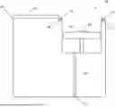
FIG. 5 is a side, partial x-ray view of the transport chamber of FIG. 4 in the materials transport state in accordance with an embodiment of the present invention.
FIG. 6 is a top view of an alternate transport chamber used in the system of FIG. 1 in a materials reception state or testing state in accordance with an embodiment of the present invention.
FIG. 7 is a top view of the transport chamber of FIG. 6 in a materials transport state in accordance with an embodiment of the present invention.
DETAILED DESCRIPTION
In the following description, certain specific details are set forth in order to provide a thorough understanding of various embodiments. However, one skilled in the art will understand that the disclosure may be practiced without these details. In other instances, well-known structures have not been shown or described in detail to avoid unnecessarily obscuring descriptions of the embodiments. Unless the context requires otherwise, throughout the specification and claims which follow, the word “comprise” and variations thereof, such as, “comprises” and “comprising” are to be construed in an open, inclusive sense, that is, as “including, but not limited to.” Further, headings provided herein are for convenience only and do not interpret the scope or meaning of the claimed disclosure.
Reference throughout this specification to “one embodiment” or “an embodiment” means that a particular feature, structure or characteristic described in connection with the embodiment is included in at least one embodiment. Thus, the appearances of the phrases “in one embodiment” or “in an embodiment” in various places throughout this specification are not necessarily all referring to the same embodiment. Furthermore, the particular features, structures, or characteristics may be combined in any suitable manner in one or more embodiments. Also, as used in this specification and the appended claims, the singular forms “a,” “an,” and “the” include plural referents unless the content clearly dictates otherwise. It should also be noted that the term “or” is generally employed in its sense including “and/or” unless the content clearly dictates otherwise.
In various embodiments, as shown in FIG. 1, a system 20 is shown for controlling exposure of materials when transporting between controlled environments (temperature, pressure, atmospheric composition, etc.). The system 20 includes an environmentally controlled loading chamber 22 and an environmentally controlled device 24 (e.g., a scanning electron microscope (SEM), X-ray photoelectron spectroscopy (XPS) analysis devices, low pressure vapor deposition devices (e.g., chemical vapor deposition (CVD), physical vapor deposition (PVD), etc.). The loading chamber 22 may be any enclosed device that allows for a target material to be stored in an environmentally controlled atmosphere. The environmentally controlled atmosphere may be a vacuum or a space that is occupied by a predominant non-reactive gas, such as an inert gas. Example loading chambers 22 include inert gas glove boxes or comparable devices.
A transfer chamber 32 is placed within the loading chamber 22. The transfer chamber 32 receives a target material within the environmentally controlled atmosphere of the loading chamber 22. A vacuum device 30 is coupled to the transfer chamber 32. The vacuum device 30, when activated, produces a vacuum or reduces pressure within a compartment of the transfer chamber 32. The vacuum device 30 may be partially located within the loading chamber 22 or fluidly connected to the loading chamber 22. The vacuum or reduced pressure within a compartment of the transfer chamber 32 causes a lid of the transfer chamber 32 to seal the target material within the compartment of the transfer chamber 32. After the target material has been scaled within the transfer chamber 32, the transfer chamber 32 is transported to the device 24 to undergo an operation performed by the device 24. Amongst other equipment, the device 24 includes a vacuum pump 38 that is configured to reduce atmospheric pressure within the device 24. The vacuum/reduced pressure within the device 24 allows for the seal of the transfer chamber 32 to be broken thereby exposing the target material to the other equipment within the device 24.
Example internal pressures of the transfer chamber 32 may be between 1-400 torr. Other internal pressure ranges may be used −20-200 torr. Example external pressures of the transfer chamber 32 within the loading chamber 22 may be between 750 and 770 torr. During transfer of the transfer chamber 32 to the device 24, the external chamber pressures are at atmospheric pressure −760 torr.
Referring to FIGS. 2 and 3, the transfer chamber 32 includes a compartment 42 having a stand 56 that receives target material 60. The compartment 42 is surrounded by a groove 54 cut into a top surface of the transfer chamber 32. The groove 54 is sized to receive an O-ring 52. The O-ring 52 is sized to be thicker than a depth of the groove 54. The transfer chamber 32 includes a lid 44 that is attached to a top surface of the transfer chamber 32 by one or more springs 46. The springs 46 are positioned to apply a biasing force to position/force the lid 44 away from an opening of the compartment 42. The transfer chamber 32 includes a vacuum airway 62 that is exposed at one end to the compartment 42 and at another end to the space external to the transfer chamber 32. Located within the vacuum airway 62 is a one-way check valve 64 that allows air to pass from the compartment 42 to the space external to the transfer chamber 32. The end of the vacuum airway 62 exposed to the space external to the transfer chamber 32 includes an attachment device (not shown) for connecting to a hose coupled to the vacuum device 30.
Referring to FIGS. 4 and 5, after the target material 60 is placed on the stand 56 while the transfer chamber 32 is within the loading chamber 22, an operator moves the lid 44 over the compartment 42 to make contact with the O-ring 52. Then the vacuum device 30 is activated thus reducing the pressure within the compartment 42. The reduced pressure within the compartment 42 produces a pressure differential between the atmosphere within the compartment 42 and the atmosphere external to the transfer chamber 32. This pressure differential causes the lid 44 to seal with the O-ring 52. The sealing force (i.e., pressure differential) overcomes the biasing force produced by the springs 46. At this point the transfer chamber 32 may be disengaged from the vacuum device 30, removed from the loading chamber 22, and transferred to the device 24.
Once the transfer chamber 32 with the loaded target material 60 has been delivered to the device 24, the vacuum pump 38 associated with the device 24 is activated thereby reducing atmospheric pressure within the device 24. When the atmospheric pressure within the device 24 drops below a threshold level, the biasing force due to the springs 46 causes the lid 44 to retract into the material loading position, as shown in FIGS. 2 and 3.
In various embodiments, as shown in FIGS. 6 and 7, a transfer chamber 80 includes a lid 44 that is attached to a top surface of the transfer chamber 80 via a torsional spring 86. The torsional spring 86 is selected to operate in a similar manner as the springs 46, whereby the torsional force produced by the spring 86 is overcome by the differential pressure between the compartment 42 and the external atmosphere of the transfer chamber 80 when in the transport configuration. Once the pressure differential between the compartment 42 and the area external to the transfer chamber 80 drops below the threshold level, the torsional spring 86 rotates the lid 44 into its material loading position (FIG. 6). It can be appreciated by one of ordinary skill, that other biasing devices, such as a spring hinge, may be used for performing similar biasing functions as performed by the springs 46, 86.
In various embodiments, the O-ring may be received within a groove on the underside of the lid.
EXPRESSED EMBODIMENTS
Embodiment 1. A transport device comprising a housing, a chamber exposed to a top surface of the housing, a lid configured to cover the vacuum chamber, and a biasing device configured to provide a force to the lid, such that the lid is forced away from covering the chamber.
Embodiment 2. The device of the foregoing Embodiment, further comprising an airway having a first end connected to the chamber and a second end exposed to an environment external to the housing and a check valve received within the airway.
Embodiment 3. The device of the foregoing Embodiments, further comprising a nozzle receiver configured to attach to a hose from a vacuum device.
Embodiment 4. The device of the foregoing Embodiments, further comprising a seal disposed on a surface of the housing around the chamber or adjacent an outer edge on a bottom surface of the lid.
Embodiment 5. The device of Embodiment 4, wherein the seal comprises a groove within the surface of the housing around the chamber or adjacent the outer edge on the bottom surface of the lid and an O-ring at least partially received within the groove.
Embodiment 6. The device of the foregoing Embodiments, wherein the force provided by the biasing device is less than a force associated with a difference between atmospheric pressure and a pressure value at a threshold amount below atmospheric pressure, wherein the pressure value at the threshold amount below atmospheric pressure is experienced within the chamber with the lid positioned over the chamber.
Embodiment 7. The device of the foregoing Embodiments, wherein the biasing device comprises a spring.
Embodiment 8. The device of Embodiment 7, wherein the spring comprises a torsional spring.
Embodiment 9. The device of Embodiment 7, wherein the spring comprises two tension springs.
Embodiment 10. A system comprising an environmentally controlled device and a transport device configured to be received within the environmentally controlled device in a transport state. The transport device comprising a housing, a chamber exposed to a top surface of the housing, a lid configured to cover the vacuum chamber, and a biasing device configured to provide a force to the lid, such that the lid is forced away from covering the chamber.
Embodiment 11. The system of the foregoing Embodiment, wherein the transport device further comprises an airway having a first end connected to the chamber and a second end exposed to an environment external to the housing and a check valve received within the airway.
Embodiment 12. The system of the foregoing Embodiments, wherein the transport device further comprises a receiver configured to attach to a hose from a vacuum device.
Embodiment 13. The system of the foregoing Embodiments, wherein the transport device further comprises a seal disposed on a surface of the housing around the chamber or adjacent an outer edge on a bottom surface of the lid.
Embodiment 14. The system of Embodiment 13, wherein the seal comprises a groove within the surface of the housing around the chamber or adjacent the outer edge on the bottom surface of the lid and an O-ring at least partially received within the groove.
Embodiment 15. The system of the foregoing Embodiments, wherein the force provided by the biasing device is less than a force associated with a difference between atmospheric pressure and a pressure value at a threshold amount below atmospheric pressure, wherein the pressure value at the threshold amount below atmospheric pressure is experienced within the chamber with the lid positioned over the chamber.
Embodiment 16. The system of the foregoing Embodiments, wherein the biasing device comprises a spring.
Embodiment 17. The system of Embodiment 16, wherein the spring comprises a torsional spring.
Embodiment 18. The system of Embodiment 16, wherein the spring comprises two tension springs.
Embodiment 19. A method for transporting an environmentally sensitive material. The method comprising loading the environmentally sensitive material in a transfer chamber, moving a lid with an opening biasing force into a closed position, reducing pressure within the transfer chamber to a first value capable of overcoming the opening biasing force, moving the transfer chamber to an environmentally controlled device, and reducing pressure within the environmentally controlled device to a second value to allow the opening biasing force to overcome the differential between the first value and the second value.
Embodiment 20. The method of Embodiment 19, wherein a difference between the first value and the second value produces a holding force of the lid in the closed position that is less than the opening biasing force.
From the foregoing it will be appreciated that, although specific embodiments of the disclosure have been described herein for purposes of illustration, various modifications may be made without deviating from the spirit and scope of the disclosure.
Claims
1. A transport device comprising:
a housing;
a chamber within the housing, the chamber being exposed to a top surface of the housing;
a lid configured to cover the chamber; and
a biasing device configured to provide a force to the lid, such that the lid is forced away from covering the chamber.
2. The device of claim 1, further comprising:
an airway having a first end connected to the chamber and a second end exposed to an environment external to the housing; and
a check valve received within the airway.
3. The device of claim 2, further comprising a receiver configured to attach to a hose from a vacuum device.
4. The device of claim 2, further comprising a seal disposed on a surface of the housing around the chamber or adjacent an outer edge on a bottom surface of the lid.
5. The device of claim 4, wherein the seal comprises:
a groove within the surface of the housing around the chamber or adjacent the outer edge on the bottom surface of the lid; and
an O-ring at least partially received within the groove.
6. The device of claim 1, wherein the force provided by the biasing device is less than a force associated with a difference between atmospheric pressure and a pressure value at a threshold amount below atmospheric pressure, wherein the pressure value at the threshold amount below atmospheric pressure is experienced within the chamber with the lid positioned over the chamber.
7. The device of claim 1, wherein the biasing device comprises a spring.
8. The device of claim 7, wherein the spring comprises a torsional spring.
9. The device of claim 7, wherein the spring comprises two tension springs.
10. A system comprising:
an environmentally controlled device; and
a transport device configured to be received within the environmentally controlled device in a transport state, the transport device comprising:
a housing;
a chamber within the housing, the chamber being exposed to a top surface of the housing;
a lid configured to cover the chamber; and
a biasing device configured to provide a force to the lid, such that the lid is forced away from covering the chamber.
11. The system of claim 10, wherein the transport device further comprises:
an airway having a first end connected to the chamber and a second end exposed to an environment external to the housing; and
a check valve received within the airway.
12. The system of claim 11, wherein the transport device further comprises a receiver configured to attach to a hose from a vacuum device.
13. The system of claim 11, wherein the transport device further comprises a seal disposed on a surface of the housing around the chamber or adjacent an outer edge on a bottom surface of the lid.
14. The system of claim 13, wherein the seal comprises:
a groove within the surface of the housing around the chamber or adjacent the outer edge on the bottom surface of the lid; and
an O-ring at least partially received within the groove.
15. The system of claim 10, wherein the force provided by the biasing device is less than a force associated with a difference between atmospheric pressure and a pressure value at a threshold amount below atmospheric pressure, wherein the pressure value at the threshold amount below atmospheric pressure is experienced within the chamber with the lid positioned over the chamber.
16. The system of claim 10, wherein the biasing device comprises a spring.
17. The system of claim 16, wherein the spring comprises a torsional spring.
18. The system of claim 16, wherein the spring comprises two tension springs.
19. A method for transporting an environmentally sensitive material, the method comprising:
loading the environmentally sensitive material into a transfer chamber;
moving a lid with an opening biasing force into a closed position;
reducing pressure within the transfer chamber to a first value capable of overcoming the opening biasing force;
moving the transfer chamber to an environmentally controlled device; and
reducing pressure within the environmentally controlled device to a second value to allow the opening biasing force to overcome the differential between the first value and the second value.
20. The method of claim 19, wherein a difference between the first value and the second value produces a holding force of the lid in the closed position that is less than the opening biasing force.
Images & Drawings included:


Sources:
- United States Patent and Trademark Office - verify current appl. status at the USPTO↗
Similar patent applications:
- » 20190185273
Transporting device, vacuum arrangement, transporting roller and method - » 20070231111
Vacuum transport device with movable guide rail - » 20100238249
Vacuum transport device with non-uniform belt hole pattern - » 20130214684
Method and device for transporting vacuum arc plasma - » 20170062174
TRANSPORT DEVICE, TREATMENT DEVICE, VACUUM DEVICE, AND CHARGED PARTICLE BEAM DEVICE - » 20260063236
VACUUM-INSULATED TRANSPORT PIPE DEVICE AND PIPELINE TRANSPORT SYSTEM - » 20210138803
Active airflow control device for vacuum paper transport - » 20210170766
Active airflow control device for vacuum paper transport - » 20100213666
Media transport device with vacuum-controlled positioning - » 20100080673
TRANSPORTING DEVICE FOR A VACUUM PROCESSING APPARATUS, DRIVE DEVICE FOR A COMPONENT OF A VACUUM PROCESSING APPARATUS, AND A VACUUM PROCESSING APPARATUS
Recent applications in this class:
- » 20260077935 2026-03-19
BUCKET BODY FOR VACUUM BUCKET AND VACUUM BUCKET - » 20260077934 2026-03-19
INTEGRATED BOX FOR VACUUM BUCKET AND VACUUM BUCKET - » 20260054911 2026-02-26
KEEP-FRESH CONTAINER - » 20260015151 2026-01-15
VACUUM PUMP AND VALVE SYSTEM FOR USE WITH VACUUM-RETENTION SYSTEM - » 20250382119 2025-12-18
HEAT PRESERVATION APPLIANCE - » 20250368421 2025-12-04
VACUUM FOOD STORAGE BARREL - » 20250313397 2025-10-09
SEALED SHIPPING BOX HAVING PANELS WITH VACUUM RETENTION MECHANISMS - » 20250236449 2025-07-24
AUTOMATED VACUUM CANISTER - » 20250229970 2025-07-17
MASON JAR SEALING STRUCTURE - » 20250051079 2025-02-13
RECEPTACLE FOR STORING AND PRESERVING A CARTRIDGE HAVING A NOZZLE FOR DISPENSING A POLYMERISABLE RESIN