CONVEYANCE DEVICE AND IMAGE FORMING SYSTEM
US20260145896A1
2026-05-28
19/394,047
2025-11-19
Smart Summary: A conveyance device helps move materials, like paper, from a supplier to a printer. It has a system that can tell if multiple sheets are stuck together when being fed. There’s also a sensor that checks the type of material being used. If the sensor finds a problem with the material, it can divert it away from the printer so it doesn’t get printed on. Additionally, if multiple sheets are detected, those sheets are also sent away through a separate path. 🚀 TL;DR
Abstract:
A conveyance device includes: a conveyance route that conveys a recording material supplied from a recording material supplier to an image former; a multiple feeding detector that detects multiple feeding of the recording material supplied from the recording material supplier; a medium sensor that detects characteristic information corresponding to a characteristic of the recording material; and a branch route that branches off the conveyance route at a branch portion on the conveyance route and purges the recording material whose characteristic information has been detected by the medium sensor, without causing the recording material to pass through the image former. The recording material about which the multiple feeding has been detected by the multiple feeding detector is purged via the branch route.
Inventors:
- Hiroyuki YOSHIKAWA 28 🇯🇵 Toyohashi-shi, Japan
- Junichi Masuda 23 🇯🇵 Toyokawa-shi, Japan
- Satoshi Ogata 55 🇯🇵 Tokyo, Japan
- Daichi SUZUKI 30 🇯🇵 Tokyo, Japan
- Kunihiko KANOU 5 🇯🇵 Tokoname-shi, Japan
- Akimasa ISHIKAWA 10 🇯🇵 Tokyo, Japan
- Bowen YANG 2 🇯🇵 Tokyo, Japan
- Tomomi IZAWA 2 🇯🇵 Tokorozawa-shi, Japan
Assignee:
- Konica Minolta, Inc. 4,648 🇯🇵 Tokyo, Japan
Applicant:
Interested in similar patents?
Get notified when new applications in this technology area are published.
Classification:
B65H29/62 » CPC main
Delivering or advancing articles from machines; Advancing articles to or into piles; Article switches or diverters diverting faulty articles from the main streams
B65H7/12 » CPC further
Controlling article feeding, separating, pile-advancing, or associated apparatus, to take account of incorrect feeding, absence of articles, or presence of faulty articles by feelers or detectors responsive to presence of faulty articles or incorrect separation or feed responsive to double feed or separation
B65H31/00 » CPC further
Pile receivers
B65H2511/13 » CPC further
Dimensions; Position; Numbers; Identification; Occurrences; Size; Dimensions Thickness
B65H2515/805 » CPC further
Physical entities not provided for in groups or Humidity
B65H2515/81 » CPC further
Physical entities not provided for in groups or Rigidity; Stiffness; Elasticity
B65H2553/20 » CPC further
Sensing or detecting means using electric elements
B65H2701/20 » CPC further
Handled material; Storage means Features of handled material other than dimensional aspect, use, or nature
Description
CROSS-REFERENCE TO RELATED APPLICATION
The entire disclosure of Japanese patent application No. 2024-205111, filed on Nov. 26, 2024, is incorporated herein by reference in its entirety.
BACKGROUND OF THE INVENTION
1. Technical Field
The present invention relates to a conveyance device and an image forming system.
2. Description of Related art
In image formation on recording materials such as sheets, the recording materials are supplied to an image former one by one. If a state in which the multiple recording materials overlap each other, that is, multiple feeding occurs, appropriate image formation cannot be performed. For this reason, for example, as disclosed in Japanese Unexamined Patent Application Publication No. 2018-095424, a technique of detecting multiple feeding of recording materials has been proposed.
Furthermore, in recent years, images have been formed on various types of recording materials. Image quality can be improved by adjusting image formation conditions in accordance with the characteristic of a recording material to be used. For example, in electrophotographic image formation, conditions such as a toner transfer voltage and a toner fixing temperature are adjusted in accordance with the characteristic of a recording material. For example, Japanese Unexamined Patent Application Publication No. 2024-000064 discloses a technique of providing, on a conveyance route, a sensor for detecting the characteristic of a recording material.
SUMMARY OF THE INVENTION
When recording materials about which multiple feeding has been detected are carried into an image former, there is a possibility that a malfunction occurs in the image former. Further, there is a possibility that charging, folding, or the like occurs in the recording materials after characteristic detection by a sensor. If the recording materials are carried into the image former as they are, there is a possibility that a malfunction occurs in the image former.
It is desirable to allow the recording materials about which the multiple feeding has been detected and the recording materials after the characteristic detection by the sensor to be ejected without passing the image former. On the other hand, it is desirable to suppress an increase in size of an apparatus owing to this ejection mechanism.
The present invention has been made in view of the above circumstances, and an object of the present invention is to provide a conveyance device and an image forming system capable of preventing occurrence of a malfunction in an image former owing to an inappropriate recording material and suppressing an increase in size of an apparatus.
To achieve at least one of the abovementioned objects, according to an aspect of the present invention, a conveyance device includes: a conveyance route that conveys a recording material supplied from a recording material supplier to an image former; a multiple feeding detector that detects multiple feeding of the recording material supplied from the recording material supplier; a medium sensor that detects characteristic information corresponding to a characteristic of the recording material; and a branch route that branches off the conveyance route at a branch portion on the conveyance route and purges the recording material whose characteristic information has been detected by the medium sensor, without causing the recording material to pass through the image former, wherein the recording material about which the multiple feeding has been detected by the multiple feeding detector is purged via the branch route.
BRIEF DESCRIPTION OF THE DRAWINGS
The advantages and features provided by one or more embodiments of the present invention will be fully understood in conjunction with the following detailed description and the accompanying drawings. It should be however understood that these embodiments are merely illustrative and are not intended to limit the present invention.
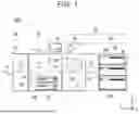
FIG. 1 is a diagram illustrating an example of a schematic configuration of an image forming system according to an embodiment;
FIG. 2 is a block diagram illustrating an example of a configuration of an image forming apparatus illustrated in FIG. 1;
FIG. 3 is a block diagram illustrating an example of a configuration of a sheet characteristic detection mechanism illustrated in FIG. 2;
FIG. 4 is a diagram illustrating an example of a specific configuration of the sheet characteristic detection mechanism illustrated in FIG. 1;
FIG. 5 is a diagram illustrating an example of configurations of a basis weight sensor and a moisture percentage sensor illustrated in FIG. 4;
FIG. 6 is a diagram illustrating an example of a configuration of a size sensor illustrated in FIG. 4;
FIG. 7 is a diagram illustrating an example of a configuration of a sheet thickness sensor illustrated in FIG. 4;
FIG. 8 is a diagram illustrating an example of the configuration of the basis weight sensor illustrated in FIG. 4;
FIG. 9 is a diagram illustrating an example of the configuration of the moisture percentage sensor illustrated in FIG. 4;
FIG. 10 is a diagram illustrating an example of a configuration of a stiffness sensor illustrated in FIG. 4;
FIG. 11 is a diagram illustrating an example of a configuration of a surface property sensor illustrated in FIG. 4;
FIG. 12 is a diagram illustrating an example of a configuration of a resistance sensor illustrated in FIG. 4;
FIG. 13 is a flowchart illustrating an example of processing performed by a controller illustrated in FIG. 2; and
FIG. 14 is a flowchart illustrating an example of processing subsequent to the processing of the flowchart illustrated in FIG. 13.
DETAILED DESCRIPTION
Hereinafter, one or more embodiments of the present invention will be described with reference to the drawings. However, the scope of the invention is not limited to the disclosed embodiments.
In the description of the drawings, the same components are denoted by the same reference signs, and the redundant description is omitted. In addition, dimensional ratios in the drawings are exaggerated for convenience of the illustration and may be different from actual ratios. In the drawings, a top-bottom direction is defined as a Z direction, a front direction and a rear direction of an image forming system or a conveyance device are defined as a Y direction, and a direction orthogonal to the Y and Z directions is defined as an X direction. The X direction is also referred to as a conveyance direction of a sheet. The Y direction is also referred to as a width direction.
Embodiment
<Overall Configuration of Image Forming System 1000>
FIG. 1 is a diagram illustrating a schematic configuration of an image forming system 1000 according to an embodiment. FIG. 2 is a block diagram illustrating a hardware configuration of the image forming system 1000. In the image forming system 1000, an image is formed on a recording material. Here, the image forming system 1000 forms an image on a sheet 90. Examples of the sheet 90 include a printing sheet and various films. The sheet 90 is produced using, for example, plant-derived mechanical pulp and/or chemical pulp. Examples of the sheet 90 include coated paper, uncoated paper, and the like. Examples of the coated paper include gloss paper, matte paper, and the like. Examples of the uncoated paper include plain paper, high-quality paper, and the like. The recording material may be made of resin, metal, or the like.
The image forming system 1000 includes, for example, an image forming apparatus 10, a post-processing device 40, and a conveyance device 50. The sheet 90 is conveyed to the conveyance device 50, the image forming apparatus 10, and the post-processing device 40 in this order. In other words, the conveyance device 50, the image forming apparatus 10, and the post-processing device 40 are arranged in this order from the upstream side in the conveyance direction of the sheet 90. The image forming apparatus 10, the post-processing device 40, and the conveyance device 50 are mechanically and electrically connected to each other. The conveyance device 50 includes, for example, a sheet feed mechanism 20 and a sheet characteristic detection mechanism 30.
The image forming apparatus 10 forms an image on the sheet 90 conveyed from the conveyance device 50. The image forming apparatus 10 includes a controller 11, a storage 12, an image former 13, a sheet feeder and conveyor 14, an operation panel 15, a printer controller 17, a communicator 19, and the like. The components of the image forming apparatus 10 are connected to each other via a signal line such as a bus, for example.
The controller 11 includes, for example, a CPU, a ROM, a RAM, and the like. The CPU is an abbreviation for “central processing unit”. The ROM is an abbreviation for “read only memory”. The RAM is an abbreviation for “random access memory”. The controller 11 performs various kinds of processing by executing a program stored in the ROM or the storage 12 to control each component of the apparatus and perform various kinds of arithmetic processing. The controller 11 includes, for example, an overall controller 111, an engine controller 112, a sheet characteristic detection mechanism controller 113, a post-processing device controller 114, a sheet feed mechanism controller 115, and a conveyance and image formation controller 116.
The storage 12 includes, for example, a ROM, a RAM, an auxiliary storage, and the like. Various programs and various kinds of data are stored in the ROM in advance. The RAM serves as a workspace and temporarily stores programs and data. The auxiliary storage is, for example, a hard disk or the like, and stores various programs and various kinds of data.
The storage 12 stores, for example, sheet information on the sheet 90. The sheet information includes, for example, information on the brand of the sheet 90, the size of the sheet 90, the basis weight of the sheet 90, the type of the sheet 90, and the like. Examples of the size of the sheet 90 include the width and the length of the sheet 90. Examples of the type of the sheet 90 include gloss coated paper, matte coated paper, plain paper, high-quality paper, rough paper, and the like. The brand of the sheet 90 may be stored in the storage 12. The storage 12 may store an algorithm or the like used for determination of a control parameter. A paper profile may be stored in the storage 12.
The image former 13 forms an image on the sheet 90 by, for example, an electrophotographic method. The image former 13 includes, for example, a writer, a photosensitive drum, a developing device, and the like. A two-component developer containing toner and a carrier is stored in the developing device, for example. The writer, the photosensitive drum, the developing device, and the like each have a configuration corresponding to basic colors such as yellow (Y), magenta (M), cyan (C), and black (K), for example. The image former 13 further includes, for example, an intermediate transfer belt, a secondary transferer, and a fixer. In the image former 13, toner images are formed on the photosensitive drum by the developing device. The toner images are superimposed on each other on the intermediate transfer belt, and are transferred onto the sheet 90 in the secondary transferer. The toner images transferred to the sheet 90 are heated and pressurized in the fixer. Thus, the toner images are fixed on the sheet 90.
The sheet feeder and conveyor 14 includes, for example, conveyance routes 141 and 142, a plurality of sheet feed trays 145, and the like. Each of the conveyance routes 141 and 142 includes, for example, a conveyance path, a plurality of conveyance roller pairs provided along the conveyance path, and a drive motor that drives the conveyance roller pairs. The sheet feeder and conveyor 14 further includes, for example, a feed roller. The feed roller feeds the uppermost one of a plurality of the sheets 90 placed in the sheet feed tray 145, to the conveyance route 141. A conveyance route 341 of the conveyance device 50 is connected to the conveyance route 141.
The conveyance route 141 conveys the sheet 90 from the sheet feed tray 145 to the image former 13. The conveyance route 141 conveys the sheet 90, on which the image has been formed by the image former 13, to the post-processing device 40. In the post-processing device 40, the sheet 90 is ejected onto a sheet ejection tray 41. In a case where images are formed on the front and back surfaces of the sheet 90, that is, in a case where double-sided printing is performed, the conveyance route 142 is used. The sheet 90 having an image formed on one side is conveyed to the conveyance route 142. The conveyance route 142 is located in a lower portion of an apparatus main body, for example. The front and back sides of the sheet 90 are reversed in a switchback route of the conveyance route 142. Thereafter, the sheet 90 is conveyed to the conveyance route 141.
The operation panel 15 includes, for example, a touch panel, a numeric keypad, a start button, a stop button, and the like. The operation panel 15 displays a state of the image forming apparatus 10 or the image forming system 1000. The operation panel 15 may be used for, for example, input of an instruction from a user. To the operation panel 15, for example, the type of the sheet 90, and the like are input from the user.
The printer controller 17 acquires a print job. For example, the print job is transmitted from a terminal device such as a PC to the image forming system 1000. The print job may be input to the operation panel 15. The PC is an abbreviation for “personal computer”. The print job includes, for example, print data described in a PDL format or a PDF format. The PDL is an abbreviation for “page description language”. The print data is rasterized by the printer controller 17 and is converted into image data for each page. The image data for each page is temporarily stored in, for example, a page memory. The image data stored in the page memory is read and stored in a buffer at a predetermined timing. The image data stored in the buffer is output as an exposure signal to the writer for each main scanning line in synchronization with the writing timing.
The communicator 19 is an interface for communicating with other devices.
When the print job is acquired by the printer controller 17, the overall controller 111 causes the engine controller 112 to execute the print job, based on setting information of the print job.
The engine controller 112 controls the post-processing device controller 114, the sheet feed mechanism controller 115, and the conveyance and image formation controller 116 to perform processing concerning image formation. The post-processing device controller 114 controls the post-processing device 40. Specifically, the post-processing device controller 114 transmits, to the post-processing device 40, a timing at which the sheet 90 is conveyed, setting information of the post-processing for the sheet 90 to be conveyed, and the like. The sheet feed mechanism controller 115 controls the sheet feed mechanism 20. Specifically, the sheet feed mechanism controller 115 transmits, to the sheet feed mechanism 20, an instruction concerning the sheet feed tray 245 to be used and an instruction concerning, for example, a timing at which the sheet 90 is conveyed. The sheet feed mechanism controller 115 may receive information from the sheet feed mechanism 20.
The conveyance and image formation controller 116 controls the image former 13 and the sheet feeder and conveyor 14. Specifically, the conveyance and image formation controller 116 controls image formation conditions, a timing of image formation, and feed and conveyance of the sheet 90.
The sheet characteristic detection mechanism controller 113 controls the sheet characteristic detection mechanism 30 in response to an instruction from the engine controller 112. Specifically, the sheet characteristic detection mechanism controller 113 controls a sensor included in the sheet characteristic detection mechanism 30.
The post-processing device 40 performs post-processing on the sheet 90 conveyed from the image forming apparatus 10, in accordance with the settings of the print job. The post-processing device 40 includes, for example, sheet ejection trays 41 and 42, a post-processor 43, and a conveyance route 441. The post-processing device 40 may further include a controller, a storage, a conveyor, a communicator, and the like. The components of the post-processing device 40 are connected to each other via a signal line such as a bus, for example.
The sheet 90 conveyed on the conveyance route 441 is ejected to the sheet ejection trays 41 and 42. The sheet ejection trays 41 and 42 are configured to be selectable in accordance with, for example, the settings of the print job. The conveyance route 441 is connected to the conveyance route 141 of the image forming apparatus 10. In the post-processor 43, post-processing is performed on the sheet 90 conveyed from the conveyance route 141. Examples of the post-processing include stapling processing, punching processing, cutting processing, folding processing, bookbinding processing, and the like. The post-processing device 40 may eject the sheet 90 to the sheet ejection tray 41 or 42 without performing the post-processing on the sheet 90.
The conveyance device 50 including the sheet feed mechanism 20 and the sheet characteristic detection mechanism 30 supplies the sheet 90 to the image forming apparatus 10, and causes the sheet characteristic detection mechanism 30 to detect the characteristic of the sheet 90.
The sheet feed mechanism 20 includes, for example, a sheet feeder and conveyor 24 and a multiple feeding detector 26. The sheet feed mechanism 20 further includes, for example, a controller, a storage, and a communicator. The components of the sheet feed mechanism 20 are connected to each other via a signal line such as a bus, for example. The sheet feeder and conveyor 24 includes, for example, a plurality of sheet feed trays 245 and a conveyance route 241. The conveyance route 241 is a conveyance path for the sheet 90 and extends from the sheet feed tray 245 to the sheet characteristic detection mechanism 30. In the sheet feed mechanism 20, the sheet 90 is supplied from each sheet feed tray 245 to the conveyance route 241. The sheet 90 supplied to the conveyance route 241 is conveyed to the sheet characteristic detection mechanism 30. Here, the sheet feed tray 245 corresponds to a specific example of a recording material supplier of the present invention.
For example, the multiple feeding detector 26 is disposed along the conveyance route 341. The controller of the sheet feed mechanism 20 causes the multiple feeding detector 26 to detect multiple feeding of the sheets 90. The term “multiple feeding” means that the plurality of sheets 90 are fed from the sheet feed tray 245 while overlapping each other.
The multiple feeding detector 26 transmits, for example, an ultrasonic wave to the sheets 90 and detects multiple feeding of the sheets 90, based on the intensity of the ultrasonic wave transmitted through the sheets. The multiple feeding detector 26 includes, for example, an ultrasonic wave transmission element and an ultrasonic wave reception element. The transmission element and the reception element are arranged, for example, at positions opposite to each other with the conveyance route 241 in between. When the multiple feeding detector 26 detects multiple feeding of the sheets 90, the controller of the sheet feed mechanism 20 causes the multiple feeding detector 26 to detect multiple feeding of the sheets 90 while continuing the conveyance of the detection target sheets 90.
FIG. 3 is a block diagram illustrating a configuration of the sheet characteristic detection mechanism 30. The sheet characteristic detection mechanism 30 includes, for example, a controller 31, a storage 32, a conveyor 34, a first detector 35, a second detector 37, an environment sensor 38, and a communicator 39. The environment sensor 38 detects at least one of a temperature and a humidity in the apparatus main body. The communicator 39 is an interface for communicating with other devices.
The controller 31 includes, for example, a CPU, a ROM, a RAM, and the like. The controller 31 controls the operations of the conveyor 34, first detector 35, second detector 37, environment sensor 38, and communicator 39. The controller 31 causes the first detector 35 and the second detector 37 to detect characteristic information corresponding to the characteristic of the sheet 90. The controller 31 transmits the characteristic information detected by the first detector 35 and second detector 37 to, for example, the controller 11. The controller 31 acquires, from the controller of the sheet feed mechanism 20, information on whether multiple feeding has been detected by the multiple feeding detector 26. Based on this information, the controller 31 controls, for example, the conveyor 34, the first detector 35, and the second detector 37.
The storage 32 includes, for example, a ROM, a RAM, and an auxiliary storage. The storage 32 stores, for example, an environment correction table in which values detected by the environment sensor 38 are associated with correction values. The controller 31 may correct the detection results of the first detector 35 and second detector 37, in accordance with the values detected by the environment sensor 38 and the environment correction table.
The conveyor 34 includes, for example, a conveyance route 341, a branch route 342, a purge tray 349, and the like. Each of the conveyance route 341 and the branch route 342 includes a conveyance path, a plurality of conveyance roller pairs provided along the conveyance path, and a drive motor that drives the conveyance roller pairs.
FIG. 4 is a schematic diagram illustrating an example of configurations of the conveyance route 341, branch route 342, and their vicinities. The conveyance route 341 is a main conveyance route. The conveyance route 341 connects the conveyance route 241 of the sheet feed mechanism 20 and the conveyance route 141 of the image forming apparatus 10. In other words, the conveyance route 241, the conveyance route 341, and the conveyance route 141 are arranged in this order from the upstream side in the conveyance direction of the sheet 90. For example, the first detector 35 is disposed along the conveyance route 341. In the conveyance direction of the sheet 90, for example, the multiple feeding detector 26 is disposed upstream of the first detector 35. The conveyance route 341 extends in a substantially horizontal direction.
The branch route 342 branches off the conveyance route 341 at a branch portion s1 on the conveyance route 341. The branch portion s1 is disposed, for example, downstream of the first detector 35 in the conveyance direction of the sheet 90. The branch route 342 is disposed between the sheet feed tray 245 and the image former 13, more specifically, between the first detector 35 and the image forming apparatus 10.
The branch route 342 connects the branch portion s1 and the purge tray 349. The sheet 90 conveyed to the branch route 342 is purged to the purge tray 349 without passing through the image former 13. For example, the second detector 37 is disposed along the branch route 342. At least a portion of the branch route 342 extends in a substantially vertical direction. A portion of the branch route 342 may be curved. The branch route 342 may have a curved shape such as an S-shape.
The first detector 35 detects, for example, the sheet characteristic of the sheet 90 conveyed on the conveyance route 341. The first detector 35 includes, for example, a plurality of medium sensors. The first detector 35 includes, for example, a size sensor 351, a sheet thickness sensor 352, a basis weight sensor 353, and a moisture percentage sensor 354. The characteristic information detected by the first detector 35 includes, for example, information on a characteristic value or a physical property value of the sheet 90. The characteristic information may include index values, such as a current value and a voltage value, indicated on the medium sensors of the first detector 35.
In the first detector 35, for example, the size sensor 351 and the sheet thickness sensor 352 are arranged in this order from the upstream side in the conveyance direction of the sheet 90. The basis weight sensor 353 and the moisture percentage sensor 354 are disposed downstream of the sheet thickness sensor 352.
When the sheet 90 passes by a detection position of the size sensor 351, the size of the sheet 90 is determined. Therefore, the size sensor 351 is preferably disposed upstream of the image formation position of the image former 13 by at least the length of the longest sheet that can be handled by the image forming system 1000. In the first detector 35, by disposing the size sensor 351 upstream of the other sensors, it is possible to further increase the distance between the size sensor 351 and the image former 13.
The sheet thickness sensor 352 is preferably disposed upstream of the basis weight sensor 353 and the moisture percentage sensor 354 in the conveyance direction of the sheet 90. Thus, since the thickness of the sheet 90 has been detected at the time of detection by the basis weight sensor 353 and the moisture percentage sensor 354, it is possible to more appropriately set the measurement ranges, measurement conditions, and the like of the basis weight sensor 353 and moisture percentage sensor 354.
FIG. 5 illustrates an example of the configurations of the basis weight sensor 353, moisture percentage sensor 354, and their vicinities. The basis weight sensor 353 and the moisture percentage sensor 354 are disposed, for example, at the same position in the conveyance direction of the sheet 90 and at positions different from each other in the width direction. With this configuration, the length of the first detector 35 as a whole in the conveyance direction can be reduced, and space saving can be achieved.
When the first detector 35 detects the characteristic information of the sheet 90, the controller 31 causes the first detector 35 to detect the characteristic information while continuing the conveyance of the detection target sheet 90. Thus, the characteristic information of the sheet 90 to be conveyed can be detected without reducing productivity. The controller 31 may cause the first detector 35 to detect the characteristic information of each of the continuously conveyed sheets 90.
For example, the characteristic information on the size, the sheet thickness, and the basis weight of the sheet 90 corresponds to the paper type, and the characteristic information on the moisture percentage of the sheet 90 corresponds to the state change of the sheet 90. Accordingly, it is possible to detect the characteristic abnormality of the sheet 90 when the type of the sheet 90 loaded in the sheet feed tray 245 is different from the settings of the print job and when the state of the sheet 90 is largely changed in the middle of the continuous printing.
The second detector 37 detects, for example, the sheet characteristic of the sheet 90 conveyed on the branch route 342. The second detector 37 includes, for example, a plurality of medium sensors. The second detector 37 includes, for example, a stiffness sensor 371, a surface property sensor 372, and a resistance sensor 373. The characteristic information detected by the second detector 37 includes, for example, information on a characteristic value or a physical property value of the sheet 90. The characteristic information may include index values, such as a current value and a voltage value, indicated on the medium sensors of the second detector 37.
In the second detector 37 disposed along the branch route 342, for example, the stiffness sensor 371, the surface property sensor 372, and the resistance sensor 373 are arranged in this order from a position close to the branch portion s1. The stiffness sensor 371 and the surface property sensor 372 may be disposed reversely. In the region where the stiffness sensor 371 is disposed, the branch route 342 preferably extends in a substantially vertical direction. Here, the term “substantially vertical” refers to a range of 90±1°.
The resistance sensor 373 is preferably disposed downstream of the stiffness sensor 371 in the conveyance direction of the sheet 90. Electric charge is accumulated on the sheet 90 after the characteristic information is detected by the resistance sensor 373, and there is a possibility that the sheet 90 is electrostatically charged. There is a possibility that the stiffness detection is not accurately performed on the sheet 90 which is electrostatically charged. By disposing the resistance sensor 373 downstream of the stiffness sensor 371, it is possible to detect the stiffness of the sheet 90 more accurately.
When the second detector 37 detects the characteristic information of the sheet 90, the controller 31 stops conveyance of the detection target sheet 90, at each of the detection positions of the stiffness sensor 371, surface property sensor 372, and resistance sensor 373. When the length of the sheet 90 in the conveyance direction is sufficient, the controller 31 may cause the stiffness sensor 371, the surface property sensor 372, and the resistance sensor 373 to detect the characteristic information at the same time. By stopping the conveyance of the sheet 90 and detecting the characteristic information, it is possible to suppress damage to the sheet 90 caused by the second detector 37.
The controller 31 may cause the second detector 37 to detect the characteristic information of all the sheets 90 to be conveyed to the second detector 37, or may cause the second detector 37 to detect characteristic information of some of the sheets 90 to be conveyed to the second detector 37.
<Configuration of First Detector 35>
FIGS. 6 to 9 illustrate an example of a specific configuration of the first detector 35.
FIG. 6 illustrates a schematic configuration of the size sensor 351. The size sensor 351 is, for example, a contactless-type medium sensor that detects the size of the sheet 90 without making contact with the sheet 90. The size sensor 351 detects the size of the sheet 90, for example, using an optical method. The size sensor 351 includes, for example, an image sensor.
The size sensor 351 includes, for example, line sensors 511 and 512. The line sensors 511 and 512 each include, for example, a plurality of photoelectric conversion elements arranged in a line. Each photoelectric conversion element includes, for example, a CIS and the like. The CIS is an abbreviation for “contact image sensor”. The line sensors 511 and 512 read, for example, a one-dimensional image.
The line sensors 511 and 512 each further include, for example, optical elements such as a light emitting element and a lens array. Light is emitted from the light emitting element toward the sheet 90 on the conveyance route 341. The length of each of the line sensors 511 and 512 is, for example, 200 mm to 300 mm. The line sensors 511 and 512 are disposed so as to overlap each other in the Y direction, for example. The line sensors 511 and 512 are disposed adjacent to each other in the X direction. Thus, the entire width of the sheet 90 to be conveyed is easily read.
The size sensor 351 generates read image data by reading, with the line sensors 511 and 512, the sheet 90 conveyed at a predetermined conveyance speed. The size sensor 351 detects an edge of the sheet 90 by performing image processing on the generated read image data. Thus, characteristic information on the size of the sheet 90 is detected. The size sensor 351 may include one line sensor, or may include three or more line sensors.
FIG. 7 illustrates a schematic configuration of the sheet thickness sensor 352. The sheet thickness sensor 352 is, for example, a contact-type medium sensor that detects the thickness of the sheet 90 in contact with the sheet 90. The sheet thickness sensor 352 mechanically detects the thickness of the sheet 90, for example. The sheet thickness sensor 352 includes, for example, a conveyance roller pair 521 and a displacement sensor. When the sheet 90 is conveyed to a nip of the conveyance roller pair 521, a position of a shaft of one of rollers of the conveyance roller pair 521 is displaced in accordance with the thickness of the sheet 90. The thickness of the sheet 90 is measured by measuring the height of the displaced shaft.
The conveyance roller pair 521 includes, for example, an upper roller and a lower roller. For example, the center of the shaft of the lower roller is fixed, and the lower roller is a drive roller. The upper roller is urged so as to be contactable with and separable from the lower roller, and the upper roller is a driven roller.
The displacement sensor detects the height of the upper roller. The displacement sensor includes, for example, an actuator that comes into contact with the upper roller shaft, and an encoder that measures the rotation amount of the actuator. The sheet thickness sensor 352 detects the characteristic information on the thickness of the sheet 90, based on the detection result of the displacement sensor.
FIG. 8 illustrates a schematic configuration of the basis weight sensor 353. The basis weight sensor 353 is, for example, a contactless-type medium sensor that detects the basis weight of the sheet 90 without making contact with the sheet 90. The basis weight sensor 353 optically detects the basis weight of the sheet 90, for example. The basis weight sensor 353 includes, for example, a light emitter and a light receiver. The basis weight sensor 353 measures, for example, the amount of attenuation of light transmitted through the sheet 90 and the amount of light reflected off the sheet 90.
The basis weight sensor 353 includes, for example, a plurality of light emitters 531 and one light receiver 532. The light emitters 531 include, for example, a first light emitter 531a, a second light emitter 531b, and a third light emitter 531c. First irradiation light is emitted from the first light emitter 531a, second irradiation light is emitted from the second light emitter 531b, and third irradiation light is emitted from the third light emitter 531c. Each of the first light emitter 531a and the second light emitter 531b and the light receiver 532 are disposed opposite each other with the conveyance route 341 in between. The third light emitter 531c is disposed near the light receiver 532, for example.
The light emitters 531 and the light receiver 532 are disposed near an upper guide plate 3411 and a lower guide plate 3412. The upper guide plate 3411 and the lower guide plate 3412 are opposite to each other in the Z direction with the conveyance route 341 in between. The upper guide plate 3411 has an opening a12, and the lower guide plate 3412 has an opening a22. The opening a22 is provided at a position opposite to the opening a12. The opening a12 and the opening a22 have the same planar shape, for example. The opening a12 and the opening a22 have, for example, a quadrangular planar shape. For example, a transparent sheet 534a is attached to the opening a12, and a transparent sheet 534b is attached to the opening a22. By attaching the sheets 534a and 534b to the openings a12 and a22, it is possible to suppress adhesion of foreign matter, such as paper dust from the sheet 90 passing through the conveyance route 341, to the light emitters 531 and the light receiver 532. The sheets 534a and 534b are made of, for example, PET or the like. The sheets 534a and 534b are configured to allow the first irradiation light, the second irradiation light, and the third irradiation light to transmit therethrough. The PET is an abbreviation for “polyethylene terephthalate”.
The first irradiation light emitted from the first light emitter 531a includes light of a first wavelength. The first wavelength is, for example, a wavelength longer than a wavelength in a visible light band, and is, for example, a wavelength in a near-infrared band. More particularly, the first wavelength is, for example, 750 nm to 900 nm. The conveyance route 341 is irradiated with the first irradiation light through the openings a12 and a22. The first irradiation light transmitted through the conveyance route 341 is received by the light receiver 532.
The second irradiation light emitted from the second light emitter 531b includes light of a second wavelength. The second wavelength is, for example, a wavelength in a blue band included in the visible light band. More particularly, the second wavelength is, for example, 400 nm to 470 nm. The conveyance route 341 is irradiated with the second irradiation light through the openings a12 and a22. The second irradiation light transmitted through the conveyance route 341 is received by the light receiver 532.
The third irradiation light emitted from the third light emitter 531c includes light of a third wavelength. The third wavelength is, for example, a wavelength in a green band included in the visible light band. More particularly, the third wavelength is, for example, 495 nm to 570 nm. The third wavelength is different from the first wavelength and the second wavelength. The third irradiation light is reflected off a reflector 533 and received by the light receiver 532. The reflector 533 is provided near the opening a22 of the lower guide plate 3412, for example. The reflector 533 is coated with green, which is the same color as the third irradiation light, and reflects the third irradiation light, for example.
In the basis weight sensor 353, for example, the first light emitter 531a and the second light emitter 531b emit the first irradiation light and the second irradiation light at different timings. The light receiver 532 detects the light amounts of the received first irradiation light and second irradiation light.
The basis weight sensor 353 detects the characteristic information on the basis weight of the sheet 90, based on the transmittance of each of the first irradiation light and the second irradiation light transmitted through the sheet 90 and the reflectance of the third irradiation light reflected off the sheet 90, for example. The basis weight sensor 353 may determine the type of the sheet 90 from the characteristic information and determination criteria stored in the storage 12.
FIG. 9 is a diagram illustrating a schematic configuration of the moisture percentage sensor 354. The moisture percentage sensor 354 is, for example, a contactless-type medium sensor that detects the moisture percentage of the sheet 90 without making contact with the sheet 90. The moisture percentage sensor 354 optically detects the moisture percentage of the sheet 90, for example. The first detector 35 may include a moisture content sensor instead of the moisture percentage sensor 354.
The moisture percentage sensor 354 includes, for example, a first light emitter 541, a second light emitter 542, a light receiver 543, a temperature detection sensor 544, lenses 545 and 546, and the like. The first light emitter 541 and the second light emitter 542 each emit light toward the sheet 90 conveyed on the conveyance route 341.
The first light emitter 541 emits, for example, light of a wavelength in the near-infrared band. As the wavelength of the light emitted by the first light emitter 541, a band is selected in which the absorptance of the light by the sheet 90 is unlikely to change due to the moisture percentage of the sheet 90. The first light emitter 541 is, for example, an LED or the like. The LED is an abbreviation for “light emitting diode”. The first light emitter 541 emits light to the sheet 90 through the lens 545. This light is reflected off the sheet 90 and is received by the light receiver 543 through the lens 546.
The second light emitter 542 emits, for example, light of a wavelength in the near-infrared band. As the wavelength of the light emitted by the second light emitter 542, a band is selected in which the absorptance of the light by the sheet 90 is easily changed by the moisture percentage of the sheet 90. The second light emitter 542 is, for example, an LED or the like. The second light emitter 542 emits light to the sheet 90 through the lens 545. This light is reflected off the sheet 90 and is received by the light receiver 543 through the lens 546.
The light receiver 543 includes, for example, a CCD or CMOS image sensor and the like. The CCD is an abbreviation for “charge-coupled device”. The CMOS is an abbreviation for “complementary metal-oxide-semiconductor”. The moisture percentage sensor 354 detects the characteristic information on the moisture percentage of the sheet 90 based on, for example, the absorptance of the sheet 90 as to the light emitted from the first light emitter 541 and the absorptance of the sheet 90 as to the light emitted from the second light emitter 542.
<Configuration of Second Detector 37>
FIGS. 10 to 12 illustrate an example of a specific configuration of the second detector 37.
FIG. 10 illustrates a schematic configuration of the stiffness sensor 371. The stiffness sensor 371 is, for example, a contact-type medium sensor that detects the stiffness of the sheet 90 in contact with the sheet 90. The stiffness sensor 371 mechanically detects the stiffness of the sheet 90, for example.
The stiffness sensor 371 is disposed, for example, vertically below a pair of rollers 347 holding the stopped sheet 90. The rotational driving of the rollers 347 is controlled by a motor M2.
The stiffness sensor 371 includes, for example, a sheet detection sensor 710, a presser 711, a pressing force detector 712, a support mechanism 715, and a motor M1. The motor M1 moves the support mechanism 715 in the horizontal direction. Accordingly, when the stiffness sensor 371 detects the stiffness of the sheet 90, a distal end of the presser 711 connected to the support mechanism 715 is disposed at a predetermined position in the X direction. The sheet detection sensor 710 detects the presence or absence of the sheet 90 at a detection position.
The presser 711 presses a lower end of the sheet 90 from a lateral direction. The presser 711 includes, for example, a blade 711a and a base 711b contiguous to one end of the blade 711ain the horizontal direction.
The pressing force detector 712 detects a pressing force when the sheet 90 is pressed and bent by the presser 711. The pressing force detector 712 includes, for example, a load cell. Based on the pressing force detected by the pressing force detector 712, the stiffness sensor 371 detects the characteristic information on the stiffness of the sheet 90.
FIG. 11 is a diagram illustrating a schematic configuration of the surface property sensor 372. The surface property sensor 372 is also referred to as a smoothness sensor and detects the characteristic information on the smoothness of the sheet 90. The surface property sensor 372 is, for example, a contactless-type medium sensor that detects the surface property of the sheet 90 without making contact with the sheet 90. The surface property sensor 372 optically detects the surface property of the sheet 90, for example. The surface property sensor 372 detects, for example, the characteristic information on the smoothness of the sheet 90, based on specular reflection light and diffuse reflection light from the sheet 90. The surface property sensor 372 is disposed near the upper guide plate 3411 and the lower guide plate 3412, for example. The upper guide plate 3421 and the lower guide plate 3422 are provided opposite to each other left and right with the branch route 342 in between.
For example, the upper guide plate 3421 has an opening a11, and the lower guide plate 3422 has an opening a21. The opening a11 has a substantially rectangular shape. The opening a21 is disposed at a position corresponding to the opening a11 and is larger than the opening a11. In the opening a21, a pressing plate 729 of a pressing mechanism is disposed. When the pressing plate 729 moves from left to right in FIG. 10, the sheet 90 is pressed against the upper guide plate 3421, so that the sheet 90 is fixed.
The surface property is detected by the surface property sensor 372, based on the specular reflection light and the diffuse reflection light from the front surface of the sheet 90 disposed on a reference plane of the opening a11. The reference plane corresponds to an inner surface of the upper guide plate 3421.
The surface property sensor 372 includes, for example, a housing 721, a light emitter 722, a collimating lens 723, light receivers 724a and 724b, and the like. Light emitted from the light emitter 722 is specular-reflected off the front surface of the sheet 90 and received by the light receiver 724a. The light emitted from the light emitter 722 is diffuse-reflected off the front surface of the sheet 90 and received by the light receiver 724b.
The light emitter 722 is disposed such that the incident angle of the light emitted from the light emitter 722 with respect to the reference plane is 75°. The incident angle of 75° is set in accordance with the JIS standard. The reference plane is an imaginary plane including a lower surface of the upper guide plate 3421. The light emitter 722 is disposed on a substrate b1. The light emitter 722 includes a light source, such as an LED, that emits light of a predetermined wavelength. The light emitted from the light emitter 722 is turned into substantially parallel light by the collimating lens 723. The wavelength of the light emitted from the light emitter 722 is preferably in a range from more than 405 nm to less than 525 nm, more preferably in a range from more than or equal to 445 nm to less than or equal to 500 nm, most preferably around 465 nm, for example. The light emitter 722 and the light receiver 724 are disposed in a width direction, for example. The light emitter 722 and the light receiver 724 are disposed on the same X-Y plane, for example.
The light receivers 724a and 724b each include, for example, a light reception element such as a photodiode or a phototransistor. The light receiver 724a is disposed at a position of a reflection angle of 75° corresponding to the incident angle of 75° of the light emitter 722, and receives the specular reflection light. The light receiver 724b is disposed at a position of any reflection angle in a range of a reflection angle more than or equal to 0° and less than 90°, except for a position of 75°, and receives the diffuse reflection light. The position where the light receiver 724b is disposed is preferably positions of reflection angles of 60°, 30°, and 0°, more preferably two positions of 60° and 30° or one position of 60°. The light receiver 724a is disposed on a substrate b2, for example, and the light receiver 724b is disposed on a substrate b3, for example. On light reception paths of the light receivers 724a and 724b, openings a3 and a4 are provided in the housing 721. The openings a3 and a4 have, for example, the same planar shape.
FIG. 12 is a diagram illustrating a schematic configuration of the resistance sensor 373. The resistance sensor 373 is, for example, a contact-type medium sensor that detects the resistance of the sheet 90 in contact with the sheet 90. The resistance sensor 373 applies a high voltage between the front and back surfaces of the sheet 90 and detects a current value of a current flowing through the sheet 90. Based on this current value, the resistance sensor 373 detects the characteristic information on the electrical resistance of the sheet 90.
The resistance sensor 373 includes, for example, a detection roller 732, a counter roller 731, and a high-voltage power supply unit 733.
The detection roller 732 is disposed so as to be contactable with one side of the sheet 90. The detection roller 732 is made of, for example, an elastic material such as electrically conductive rubber.
The counter roller 731 is disposed opposite the detection roller 732 with the sheet 90 in between. The counter roller 731 is disposed so as to be contactable with the other side of the sheet 90. The counter roller 731 is made of, for example, a metal material. The counter roller 731 is grounded.
The high-voltage power supply unit 733 is a unit for applying a high voltage to the sheet 90. The high-voltage power supply unit 733 is electrically connected to the detection roller 732 and the counter roller 731. Thus, an electric circuit is constituted of the detection roller 732, the counter roller 731, and the high-voltage power supply unit 733. The high-voltage power supply unit 733 includes an ammeter and a high-voltage power supply circuit. The ammeter is electrically connected to the detection roller 732. The ammeter detects a current flowing due to a voltage applied in the high-voltage power supply circuit.
The high-voltage power supply circuit is electrically connected to the detection roller 732 via the ammeter. The high-voltage power supply circuit is configured to be able to apply a high voltage. A voltage is applied to the detection roller 732 from the high-voltage power supply circuit via the ammeter. The high-voltage power supply circuit is configured to be able to apply a high voltage of, for example, 1 kV to 5 kV.
<Processing of Controller 11>
FIGS. 13 and 14 are flowcharts each illustrating an example of processing performed by the controller 11. The processing illustrated in each flowchart can be performed in accordance with a program stored in the controller 11, for example. The processing illustrated in each flowchart may be performed by another controller. The processing illustrated in FIG. 13 is processing of preparing printing operation, and the processing illustrated in FIG. 14 is processing of performing printing operation.
(Step S11)
When a print job is input, the controller 11 feeds and conveys a sheet 90 to be used in the print job, based on print job setting information of the input print job. The print job is input based on an instruction sent from an external terminal such as a PC, for example. For example, the controller 11 causes the sheet feed tray 245 of the sheet feed mechanism 20 to feed the sheet 90, and causes the conveyance route 241 to convey the sheet 90. This sheet 90 is a first one of the sheets on the sheet feed tray 245.
(Step S12)
The controller 11 determines whether multiple feeding of the sheet 90 has been detected by the multiple feeding detector 26. For example, when the multiple feeding detector 26 detects the sheet 90, the controller 11 continues conveyance of the detection target sheet 90. The controller 11 controls, for example, the sheet feeder and conveyor 24 and the multiple feeding detector 26 to determine whether multiple feeding of the sheet 90 has been detected.
(Step S13)
When multiple feeding is not detected in step S12 (step S12: NO), the controller 11 causes the first detector 35 to detect characteristic information of the sheet 90. For example, when the first detector 35 detects the characteristic information of the sheet 90, the controller 11 continues the conveyance of the detection target sheet 90. The controller 11 controls the conveyor 34 and the first detector 35 to detect the characteristic information of the sheet 90, for example.
(Step S14)
After causing the first detector 35 to detect the characteristic information of the sheet 90 in step S13, the controller 11 causes the branch route 342 to convey the sheet 90 from the conveyance route 341 via the branch portion s1. The controller 11 causes the second detector 37 to detect the characteristic information of the sheet 90 conveyed by the branch route 342. For example, when the second detector 37 detects the characteristic information of the sheet 90, the controller 31 stops the conveyance of the detection target sheet 90. The controller 11 may stop the conveyance of the sheet 90 a plurality of times. After causing the second detector 37 to detect the characteristic information of the sheet 90, the controller 11 performs the processing in step S15.
(Steps S15, S16)
The controller 11 causes the purge tray 349 to eject the sheet 90 conveyed by the branch route 342. Thereafter, the controller 11 determines parameters of the respective processes in the image former 13 and the like, using the characteristic information obtained by the processing in steps S13 and S14, and proceeds to the processing in step S21. Specifically, the controller 11 determines control parameters of the respective processes of fixing, transfer, conveyance, feeding, and post-processing.
(Steps S17, S18)
When multiple feeding is detected in step S12 (step S12: YES), the controller 11 causes the branch route 342 to convey the sheet 90 from the conveyance route 341 via the branch portion s1. At this time, for example, the controller 11 continues the conveyance of the sheet 90 about which the multiple feeding has been detected, and performs the next processing in step S19, without causing the first detector 35 and the second detector 37 to detect the characteristic information of the sheet 90.
(Step S19)
The controller 11 causes the purge tray 349 to eject the sheet 90 conveyed by the branch route 342. Thereafter, for example, the controller 11 returns to the processing in step S11.
(Step S21)
The controller 11 determines whether to start execution of the print job. When determining to start execution of the print job (step S21: YES), the controller 11 proceeds to the processing in step S22. When determining not to start execution of the print job (step S21: NO), the controller 11 repeatedly performs the processing in step S21. The print job is started, for example, in response to a press of an execution start button by a user. The controller 11 may determine to start the execution of the print job at the end of the processing in step S16.
(Step S22)
First, the controller 11 feeds and conveys the sheet 90 to be used in the print job. For example, the controller 31 causes the sheet feed tray 245 to feed the sheet 90 to the conveyance route 341, and causes the conveyance route 341 to convey the sheet 90 downstream. The controller 11 may control the sheet feed mechanism 20 to consecutively feed and convey the sheets 90 from the sheet feed tray 245.
(Step S23)
The controller 11 determines whether multiple feeding of the sheet 90 has been detected by the multiple feeding detector 26. For example, when the multiple feeding detector 26 detects the sheet 90, the controller 11 continues conveyance of the detection target sheet 90. The controller 11 controls, for example, the sheet feeder and conveyor 24 and the multiple feeding detector 26 to determine whether multiple feeding of the sheet 90 has been detected.
(Step S24)
When multiple feeding is not detected in step S23 (step S23: NO), the controller 11 causes the first detector 35 to detect the characteristic information of the sheet 90. For example, when the first detector 35 detects the characteristic information of the sheet 90, the controller 11 continues the conveyance of the detection target sheet 90. The controller 11 controls the conveyor 34 and the first detector 35 to detect the characteristic information of the sheet 90, for example.
(Step S25)
After causing the first detector 35 to detect the characteristic information of the sheet 90 in step S24, the controller 31 determines whether the sheet 90 is an inappropriate sheet, based on the detected characteristic information of the sheet 90. For example, when a difference between the characteristic information of the sheet 90 set in the print job under execution and the detected characteristic information of the sheet 90 is within a predetermined range, the controller 11 determines that the sheet 90 is not an inappropriate sheet. When the difference between the characteristic information of the sheet 90 set in the print job under execution and the detected characteristic information of the sheet 90 is outside the predetermined range, the controller 11 determines that the sheet 90 is an inappropriate sheet.
For example, if a sheet different in size and type from the sheet 90 set in the print job setting is mixed in the sheet bundle, the controller 11 determines that the sheet 90 is an inappropriate sheet. For example, if the moisture percentage of the sheet 90 is significantly different from the moisture percentages of the previous sheets 90, the controller 11 determines that the sheet 90 is an inappropriate sheet. For example, if an interleaf having a different size is mixed in the sheet bundle loaded in the sheet feed tray 245, the controller 11 determines that the sheet 90 is an inappropriate sheet. For example, if the sheet 90 of a different size or paper type is added to the sheet feed tray 245 due to misunderstanding of the user, the controller 11 determines that the sheet 90 is an inappropriate sheet.
(Step S26)
When determining in step S25 that the sheet 90 is not an inappropriate sheet (step S25: NO), the controller 11 conveys the sheet 90 to the image former 13 from the conveyance route 341 via the conveyance route 141. Thus, an image is formed on the sheet 90. The sheet 90 on which the image has been formed is then ejected to the sheet ejection tray 41 of the post-processing device 40.
(Step S27)
The controller 11 determines whether the print job has been completed. When determining that the print job is not completed (step S27: NO), the controller 11 returns to the processing in step S22. When determining that the print job has been completed (step S27: YES), the controller 11 ends the processing.
(Step S41)
When determining in step S25 that the sheet 90 is an inappropriate sheet (step S25: YES), the controller 11 stops execution of the print job and ends the processing. Specifically, the controller 11 ejects the sheet 90 determined as an inappropriate sheet, to the sheet ejection tray 42 without forming an image on the sheet 90. Then, the controller 11 stops conveyance of the subsequent sheets 90.
(Steps S31, S32)
When multiple feeding is detected in step S23 (step S23: YES), the controller 11 causes the branch route 342 to convey the sheet 90 from the conveyance route 341 via the branch portion s1. At this time, for example, the controller 11 continues the conveyance of the sheet 90 about which multiple feeding has been detected, and performs the processing in step S33 without causing the first detector 35 and the second detector 37 to detect the characteristic information of the sheet 90.
(Step S33)
The controller 11 causes the purge tray 349 to eject the sheet 90 conveyed by the branch route 342. Thereafter, the controller 31 proceeds to the processing in step S27.
When determining in step S25 that the sheet 90 is an inappropriate sheet, the controller 11 may convey the sheet 90 to the branch route 342 and purge the sheet 90.
<Operation and Effect of Conveyance Device 50 and Image Forming System 1000>
Since the conveyance device 50 and the image forming system 1000 according to the present embodiment include the controller 31, the sheet 90 about which multiple feeding has been detected and the sheet 90 whose characteristic information has been detected by the first detector 35 and the second detector 37 are purged via the common branch route 342. The branch route 342 is configured not to pass through the image former 13. Therefore, it is possible to prevent occurrence of a malfunction in the image former 13 owing to the inappropriate sheet 90 and to suppress an increase in size of the apparatus. Specifically, since an ejection route is not provided for each of the detection by the first detector 35 and the detection by the second detector 37, an increase in size of the apparatus is suppressed. Hereinafter, this operation and effect will be described.
When sheets are fed from the sheet feed tray to the conveyance route, multiple feeding may occur. An appropriate image cannot be formed in a state of multiple feeding, that is, in a state in which a plurality of sheets overlap each other. Further, when the sheets in the state of multiple feeding are conveyed to the image former, a trouble such as a paper jam may occur. The occurrence of this trouble can be suppressed by switching the conveyance route of the sheet about which multiple feeding has been detected, before the sheet is conveyed to the image former, and ejecting the sheet.
Further, characteristic information on a characteristic of the sheet is detected by using the medium sensor, so that it is possible to appropriately set image formation conditions in accordance with the characteristic of the sheet. After the detection of the characteristic information by the medium sensor, the sheet may become denatured or deformed. For example, in the resistance sensor or the like, charging of the sheet may occur, and in the stiffness sensor or the like, folding or the like of the sheet may occur. When the sheet thus denatured or deformed is conveyed to the image former, troubles such as a reduction in quality of the formed image and a paper jam may occur. The occurrence of these troubles can be suppressed by ejecting the sheet whose characteristic information has been detected by the medium sensor, without conveying the sheet to the image former.
Here, in a case where conventional sheet ejection routes are combined for the above-described sheet ejection, it is conceivable to adopt a configuration in which a sheet ejection route for a sheet about which multiple feeding has been detected and a sheet ejection route for a sheet whose characteristic information has been detected by the medium sensor are separately provided. However, this configuration requires a space for installing a plurality of sheet ejection routes in the apparatus, which tends to increase the size of the apparatus.
On the other hand, according to the present embodiment, in the conveyance device 50 and the image forming system 1000, both the sheet 90 about which multiple feeding has been detected by the multiple feeding detector 26 and the sheet 90 whose characteristic information has been detected by the first detector 35 and the second detector 37 are ejected to the purge tray 349 via the common branch route 342. That is, the sheet ejection route for the sheet 90 about which multiple feeding has been detected and the sheet ejection route for the sheet 90 whose characteristic information has been detected are shared. Therefore, it is possible to realize the conveyance device 50 and the image forming system 1000 which are compact and have less trouble.
Furthermore, when multiple feeding is detected by the multiple feeding detector 26, the sheet 90 is ejected to the purge tray 349, and the characteristic information is not detected by the first detector 35 and the second detector 37. This is because it is difficult to accurately detect the characteristic information of the sheet 90 in the state of multiple feeding. In addition, when multiple feeding is detected by the multiple feeding detector 26, it is possible to continue conveyance of the sheet 90 and purge the sheet 90 at high speed.
Each of the configuration of the conveyance device 50 described above and the configuration of the image forming system 1000 including the conveyance device 50 is the main configuration for describing the features of the above-described embodiment, and the present invention is not limited to the above-described configuration and can be variously modified within the scope of the claims. Further, the present invention does not exclude a configuration of a general image forming apparatus.
For example, each of the first detector 35 and the second detector 37 may include at least one medium sensor. The first detector 35 may include a medium sensor other than the size sensor, the sheet thickness sensor, the basis weight sensor, and the moisture percentage sensor. The second detector 37 may include a medium sensor other than the stiffness sensor, the surface property sensor, and the resistance sensor.
Furthermore, although the example in which the multiple feeding detector 26 detects multiple feeding of the sheet 90 by using an ultrasonic wave has been described in the above-described embodiment, the multiple feeding detector 26 may have another configuration. The multiple feeding detector 26 may detect multiple feeding of the sheet 90, based on the length of the sheet 90 conveyed on the conveyance route 341, for example. At this time, the multiple feeding detector 26 includes, for example, a line sensor.
Furthermore, although the example in which the conveyance device 50 includes the first detector 35 and the second detector 37 has been described in the above-described embodiment, the conveyance device 50 may include one of the first detector 35 and the second detector 37. The conveyance device 50 may further include any other detector.
In the above-described embodiment, the example in which the sheet 90 whose characteristic information has been detected by the first detector 35 and the second detector 37 is ejected to the purge tray 349 via the branch route 342 has been described. However, the sheet 90 whose characteristic information has been detected by the first detector 35 and whose characteristic information has not been detected by the second detector 37 may be ejected to the purge tray 349 via the branch route 342. Alternatively, the sheet 90 whose characteristic information has not been detected by the first detector 35 and whose characteristic information has been detected by the second detector 37 may be ejected to the purge tray 349 via the branch route 342.
Furthermore, the means and method for performing various kinds of processing in the conveyance device 50 and the image forming system 1000 according to the above-described embodiment can be implemented by either a dedicated hardware circuit or a programmed computer. For example, the program may be provided by a computer-readable recording medium such as a USB memory or a DVD-ROM, or may be provided online via a network such as the Internet. In this case, the program recorded on the computer-readable recording medium is usually transferred to and stored in a storage such as a hard disk. Furthermore, the program may be provided as independent application software, or may be incorporated in software of an apparatus as one function of the apparatus.
Although embodiments of the present invention have been described and illustrated in detail, the disclosed embodiments are made for purpose of illustration and example only and not limitation. The scope of the present invention should be interpreted by terms of the appended claims.
Claims
What is claimed is:1. A conveyance device comprising:
a conveyance route that conveys a recording material supplied from a recording material supplier to an image former;
a multiple feeding detector that detects multiple feeding of the recording material supplied from the recording material supplier;
a medium sensor that detects characteristic information corresponding to a characteristic of the recording material; and
a branch route that branches off the conveyance route at a branch portion on the conveyance route and purges the recording material whose characteristic information has been detected by the medium sensor, without causing the recording material to pass through the image former,
wherein the recording material about which the multiple feeding has been detected by the multiple feeding detector is purged via the branch route.
2. The conveyance device according to claim 1, wherein the branch portion is disposed upstream of the image former in a conveyance direction of the recording material.
3. The conveyance device according to claim 1, wherein the branch route is disposed between the recording material supplier and the image former.
4. The conveyance device according to claim 1, further comprising a tray on which the recording material purged via the branch route is placeable.
5. The conveyance device according to claim 1, wherein the medium sensor is disposed on the branch route.
6. The conveyance device according to claim 5, wherein the medium sensor includes a contact-type sensor that detects the characteristic information in contact with the recording material.
7. The conveyance device according to claim 5, wherein the medium sensor includes at least one of a sensor that detects the characteristic information by applying a voltage to the recording material and a sensor that detects the characteristic information by pressing the recording material.
8. The conveyance device according to claim 5, wherein the medium sensor includes at least one of a sensor that detects the characteristic information corresponding to resistance of the recording material, a sensor that detects the characteristic information corresponding to stiffness of the recording material, and a sensor that detects the characteristic information corresponding to smoothness of the recording material.
9. The conveyance device according to claim 1, wherein the medium sensor is disposed upstream of the branch portion in a conveyance direction of the recording material.
10. The conveyance device according to claim 9, wherein the medium sensor includes a contactless-type sensor that detects the characteristic information without making contact with the recording material.
11. The conveyance device according to claim 9, wherein the medium sensor includes at least one of a sensor that detects the characteristic information corresponding to a basis weight of the recording material, a sensor that detects the characteristic information corresponding to a thickness of the recording material, and a sensor that detects the characteristic information corresponding to a moisture content of the recording material.
12. The conveyance device according to claim 1, wherein the multiple feeding detector is disposed upstream of the medium sensor in a conveyance direction of the recording material.
13. The conveyance device according to claim 12, wherein the multiple feeding detector is disposed upstream of the branch portion in a conveyance direction of the recording material.
14. The conveyance device according to claim 1, further comprising
a controller that controls the medium sensor, based on a detection result of the multiple feeding detector.
15. The conveyance device according to claim 14, wherein the controller acquires the characteristic information of the recording material about which the multiple feeding has not been detected, and controls the image former, based on the acquired characteristic information.
16. The conveyance device according to claim 14, wherein the controller does not perform detection of the characteristic information by the medium sensor or does not acquire the characteristic information, as to the recording material about which the multiple feeding has been detected.
17. The conveyance device according to claim 14, wherein
the controller controls conveyance of the recording material, and
when the medium sensor detects the characteristic information of the recording material, the controller stops conveyance of the recording material whose characteristic information has been detected.
18. The conveyance device according to claim 17, wherein the controller conveys the recording material about which the multiple feeding has been detected, without stopping the recording material at a position corresponding to the medium sensor on the branch route.
19. The conveyance device according to claim 14, wherein
the controller controls conveyance of the recording material, and
when the medium sensor detects the characteristic information of the recording material, the controller continues conveyance of the recording material whose characteristic information has been detected.
20. An image forming system comprising:
the conveyance device according to claim 1;
the recording material supplier; and
the image former.
Images & Drawings included:


Sources:
- United States Patent and Trademark Office - verify current appl. status at the USPTO↗
Similar patent applications:
- » 20200354182
Relay conveyance device, image forming system, combination of image forming system, and sheet conveyance device - » 20130011219
Booklet conveying device, image forming system, and booklet conveying method - » 20150217956
Sheet conveyance device, image forming system and control method of sheet conveyance device - » 20180307170
Image forming device, transfer medium conveyance device, image forming system, and program - » 20190243296
Sheet conveying device, image reading device incorporating the sheet conveying device, image forming apparatus incorporating the sheet conveying device, and image forming system incorporating the sheet conveying device - » 20200122491
Sheet conveying device and image forming system incorporating the sheet conveying device - » 20220342354
Sheet conveying device and image forming system incorporating the sheet conveying device - » 20220324670
Sheet conveying device and image forming system incorporating the sheet conveying device - » 20180254721
Driving device, drive system, image forming apparatus, conveyance device, and driving method - » 20180041148
Phase detecting device, motor system, image forming apparatus, conveyance device, and sensor level obtaining method
Recent applications in this class:
- » 20240375905 2024-11-14
Sheet Metal Processing Cell with Traversing Part Sorter - » 20240351817 2024-10-24
IMAGE FORMING SYSTEM FOR CONTROLLING DISCHARGE OF SHEET ON WHICH IMAGE HAS BEEN INSPECTED - » 20240092603 2024-03-21
MEDIUM PROCESSING SYSTEM - » 20230264919 2023-08-24
Medium storage device and method of controlling the medium storage device - » 20230264918 2023-08-24
Medium storage device and method of controlling the medium storage device - » 20230041762 2023-02-09
Diverter conveyor - » 20220258999 2022-08-18
Conveying apparatus - » 20220162030 2022-05-26
Conveying device and liquid discharge apparatus - » 20220135360 2022-05-05
Paper ejection apparatus, paper ejection method, and image forming system - » 20210331886 2021-10-28
CONVEYING DIRECTION SWITCHING APPARATUS AND PAPER SHEET HANDLING APPARATUS
Recent applications for this Assignee:
- » 20260148372 2026-05-28
IMAGE INSPECTION APPARATUS, IMAGE INSPECTION METHOD, AND STORAGE MEDIUM - » 20260140471 2026-05-21
IMAGE FORMING APPARATUS - » 20260138220 2026-05-21
Shrink Fitting System - » 20260133529 2026-05-14
SHEET CHARACTERISTIC DETECTION DEVICE AND IMAGE FORMING SYSTEM - » 20260126747 2026-05-07
MANAGEMENT DEVICE, MANAGEMENT SYSTEM, MANAGEMENT METHOD, AND MANAGEMENT PROGRAM PRODUCT - » 20260126745 2026-05-07
MEDIA DETECTION APPARATUS, IMAGE FORMING SYSTEM, AND RECORDING MEDIUM - » 20260118807 2026-04-30
IMAGE FORMING APPARATUS, IMAGE FORMING SYSTEM, AND STORAGE MEDIUM - » 20260116063 2026-04-30
LAMINATING DEVICE, IMAGE FORMING SYSTEM, AND STORAGE MEDIUM - » 20260114836 2026-04-30
RADIOGRAPHIC IMAGING SYSTEM - » 20260105564 2026-04-16
IMAGE DISPLAY DEVICE, IMAGE DISPLAY SYSTEM, IMAGE DISPLAY METHOD, IMAGE PROCESSING DEVICE, AND PROGRAM