EXTERNAL DRIVE FEATURE FOR A CABLE REEL
US20260145902A1
2026-05-28
19/401,286
2025-11-25
Smart Summary: A cable reel system is designed to wind and unwind cables easily. It has a special external drive feature that has a specific shape. This feature connects to an external drive source using a coupling device. The connection between the drive feature and the coupling device prevents slipping. This setup allows the external drive to automatically retract the cable when needed. 🚀 TL;DR
Abstract:
A cable reel system includes a cable reel configured to wind and unwind cable; an external drive feature integrated with the cable reel, the external drive feature having a predetermined geometric shape; a coupling device configured to interface with the external drive feature and connect to an external drive source; and wherein the external drive feature and the coupling device form a connection that prevents slippage and enables transfer of rotational motion from the external drive source to the cable reel for automated retraction of the cable.
Inventors:
- Venkata R. Penumatcha 19 🇺🇸 Plano, TX, United States
- Nicolas P. Guiffault 6 🇺🇸 Allen, TX, United States
- Larry D. Hall 4 🇺🇸 Richardson, TX, United States
Assignee:
- Optical Cable Corporation 42 🇺🇸 Roanoke, VA, United States
Applicant:
Interested in similar patents?
Get notified when new applications in this technology area are published.
Classification:
B65H75/305 » CPC main
Storing webs, tapes, or filamentary material, e.g. on reels; Cores, formers, supports, or holders for coiled, wound, or folded material, e.g. reels, spindles, bobbins, cop tubes, cans, mandrels or chucks; Constructional details; Arrangements to facilitate driving or braking Arrangements to facilitate driving by a portable drill
B65H75/4481 » CPC further
Storing webs, tapes, or filamentary material, e.g. on reels; Cores, formers, supports, or holders for coiled, wound, or folded material, e.g. reels, spindles, bobbins, cop tubes, cans, mandrels or chucks specially adapted or mounted for storing and repeatedly paying-out and re-storing lengths of material provided for particular purposes, e.g. anchored hoses, power cables involving the use of a core or former internal to, and supporting, a stored package of material; Constructional details Arrangements or adaptations for driving the reel or the material
B65H75/30 IPC
Storing webs, tapes, or filamentary material, e.g. on reels; Cores, formers, supports, or holders for coiled, wound, or folded material, e.g. reels, spindles, bobbins, cop tubes, cans, mandrels or chucks; Constructional details Arrangements to facilitate driving or braking
B65H75/44 IPC
Storing webs, tapes, or filamentary material, e.g. on reels; Cores, formers, supports, or holders for coiled, wound, or folded material, e.g. reels, spindles, bobbins, cop tubes, cans, mandrels or chucks specially adapted or mounted for storing and repeatedly paying-out and re-storing lengths of material provided for particular purposes, e.g. anchored hoses, power cables involving the use of a core or former internal to, and supporting, a stored package of material Constructional details
Description
CROSS REFERENCE TO RELATED APPLICATIONS
The present application claims the priority of U.S. Provisional Patent Application Ser. No. 63/724,477 filed Nov. 25, 2024, entitled “CABLE REEL FEATURES”, which is incorporated herein in its entirety.
BACKGROUND
Cable reels, also known as drums or spools, are cylindrical devices essential for the organized storage, transport, and dispensing of various types of electrical wires, fiber optic cables, and wire ropes. These reels are utilized across a wide range of industries, such as telecommunications, construction, entertainment and mining, to prevent tangling and ensure efficient deployment. Depending on the application and load requirements, they are constructed from diverse materials; for instance, heavy-duty steel reels are often used for industrial mining operations, while lighter plastic or plywood reels are common for commercial wiring or disposable applications. Advanced models may even include features such as spring-loaded retraction, motorized winding, or “live” connections that allow the cable to be used while still spooled.
Traditional cable reels typically include manual winding handles that require users to manually wind extended cables back onto the reel for retraction and storage. The lack of external drive connection limits retraction of extended cable to manual winding which is laborious and time consuming. Current reel designs do not allow for additional features to facilitate automated retraction. This limitation creates inefficiencies in cable management operations and increases the physical effort required by operators.
BRIEF DESCRIPTION OF THE DRAWING
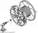
FIG. 1 is a perspective view of a cable reel and external drive source; and
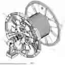
FIG. 2 is a perspective view of a cable reel, coupling device, and external drive source.
DETAILED DESCRIPTION
As discussed herein, an external drive feature 10 is provided as part of a cable reel 12 for connecting an external drive source 16 to allow retraction of extended cable 18 in lieu of manual winding. A coupling device that connects to an external drive source, such as but not limited to a motorized drill, to rotate the cable reel and retract the extended cable without utilization of the built-in manual winding handle.
As shown in FIGS. 1-2, an external drive feature 10 is incorporated into a cable reel 12. The external drive feature 10 is designed to interface with a coupling device 14 that attaches to an external drive source 16. The cable reel 12 is used for managing and retracting cable 18 that has been extended from the reel.
The external drive feature 10 is constructed with a specific shape that prevents slippage when engaged with the coupling device 14. The external drive feature 10 may take various geometric configurations including, but not limited to, triangular, square, multi-splined, round, oblong, or freeform shapes. The specific shape selected depends on the intended application and the type of external drive source 16 to be used.
The coupling device 14 serves as an interfacing component that connects the external drive source 16 to the external drive feature 10. When the coupling device 14 is properly engaged with the external drive feature 10, it forms a secure connection that prevents slippage between the two components. This connection enables the transfer of rotational force from the external drive source 16 to the cable reel 12.
The external drive source 16 may comprise any suitable motorized device capable of providing rotational motion, such as a motorized drill or other power tool. When the external drive source 16 is activated, it propels the cable reel 12 in a circular motion through the connection established by the external drive feature 10 and coupling device 14.
The cable 18 that has been extended from the cable reel 12 can be efficiently retracted onto the reel when the external drive source 16 is operated. This automated retraction eliminates the need for manual winding using a traditional manual winding handle 20, thereby reducing the labor and time required for cable management operations.
The external drive feature 10 is designed to be incorporated into the cable reel 12 without interfering with the current fitment or operation of existing cable reel systems. This allows the invention to be implemented as an enhancement to existing cable reel designs or incorporated into new cable reel products.
The versatility of the external drive feature 10 shape options allows for adaptation to various external drive sources 16 and application requirements.
As described herein, a cable reel system includes:
-
- a cable reel 12 configured to wind and unwind cable 18;
- an external drive feature 10 integrated with the cable reel 12, the external drive feature 10 having a predetermined geometric shape;
- a coupling device 14 configured to interface with the external drive feature 10 and connect to an external drive source 16; and
- wherein the external drive feature 10 and the coupling device 14 form a connection that prevents slippage and enables transfer of rotational motion from the external drive source 16 to the cable reel 12 for automated retraction of the cable 18.
In an embodiment, the external drive feature 10 has a triangular shape.
In an embodiment, the external drive feature 10 has a square shape.
In an embodiment, the external drive feature 10 has a multi-splined shape.
In an embodiment, the external drive feature 10 has a round shape.
In an embodiment, the external drive feature 10 has a oblong shape.
In an embodiment, the external drive feature 10 has a freeform shape.
As also described herein, a method of retracting cable 18 includes:
-
- providing a cable reel 12 having an external drive feature 10 with a predetermined geometric shape;
- connecting an external drive source 16 to the external drive feature 10 using a coupling device 14;
- forming a slip-resistant connection between the external drive feature 10 and the coupling device 14; and
- activating the external drive source 16 to rotate the cable reel 12 and automatically retract extended cable 18 without manual winding.
The figures and descriptions provided herein may have been simplified to illustrate aspects that are relevant for a clear understanding of the herein described devices, systems, and methods, while eliminating, for the purpose of clarity, other aspects that may be found in typical devices, systems, and methods. Those of ordinary skill may recognize that other elements and/or operations may be desirable and/or necessary to implement the devices, systems, and methods described herein. Because such elements and operations may be well known in the art, and because they do not facilitate a better understanding of the present disclosure, a discussion of such elements and operations is not provided herein. The present disclosure is deemed to inherently include all such elements, variations, and modifications to the described aspects that would be known to those of ordinary skill in the art, particularly in view of reading the present disclosure. Any headings used herein are for organizational purposes only and are not meant to be used to limit the scope of the description or the claims.
The terminology used herein is for the purpose of describing particular example embodiments or implementations only and is not intended to be limiting. As used herein, the singular forms “a”, “an”, and “the” may be intended to include the plural forms as well, unless the context clearly indicates otherwise.
The terms “comprises,” “comprising,” “includes,” “including,” “has,” “having,” and variations in form thereof are inclusive or variations in form thereof are intended to be inclusive in a manner similar to the term “comprises” as that term is interpreted when employed as a transitional word in a claim, and therefore specify the presence of stated features, integers, steps, operations, elements, and/or components, but do not preclude the presence or addition of one or more other features, integers, steps, operations, elements, components, and/or groups thereof unless explicitly stated otherwise or the context clearly requires otherwise.
The method steps, processes, and operations described herein are not to be construed as necessarily requiring their performance in the particular order discussed or illustrated, unless specifically identified as an order of performance. It is also to be understood that additional or alternative steps may be employed.
When an element or layer is referred to as being “on”, “engaged to”, “connected to” or “coupled to” another element or layer, it may be directly on, engaged, connected or coupled to the other element or layer, or intervening elements or layers may be present. In contrast, when an element is referred to as being “directly on,” “directly engaged to”, “directly connected to” or “directly coupled to” another element or layer, there may be no intervening elements or layers present. Other words used to describe the relationship between elements should be interpreted in a like fashion (e.g., “between” versus “directly between,” “adjacent” versus “directly adjacent,” etc.). As used herein, the term “and/or” includes any and all combinations of one or more of the associated listed items.
Although the terms first, second, third, etc., may be used herein to describe various elements, components, regions, layers and/or sections, these elements, components, regions, layers and/or sections should not be limited by these terms. These terms may be only used to distinguish one element, component, region, layer or section from another element, component, region, layer or section. Terms such as “first,” “second,” and other numerical terms when used herein do not imply a sequence or order unless clearly indicated by the context. Thus, a first element, component, region, layer or section discussed below could be termed a second element, component, region, layer or section without departing from the teachings of the exemplary embodiments and implementations.
Unless otherwise defined, all terms (including technical and scientific terms) used herein have the same meaning as commonly understood by one of ordinary skill in the art to which this subject matter belongs. It will be further understood that terms, such as those defined in commonly used dictionaries, should be interpreted as having a meaning that is consistent with their meaning in the context of the specification and relevant art and should not be interpreted in an idealized or overly formal sense unless expressly so defined herein. For brevity and/or clarity, well-known functions or constructions may not be described in detail herein.
The terms “for example” and “such as” mean “by way of example and not of limitation.” The subject matter described herein is provided by way of illustration for the purposes of teaching, suggesting, and describing, and not limiting or restricting. Combinations and alternatives to the illustrated embodiments and implementations are contemplated, described herein, and set forth in the claims.
The term “exemplary” is used herein to mean serving as an example, instance, or illustration. Any aspect or design described herein as “exemplary” is not necessarily to be construed as preferred or advantageous over other aspects or designs. Similarly, examples are provided herein solely for purposes of clarity and understanding and are not meant to limit the subject innovation or portion thereof in any manner.
For convenience of discussion herein, when there is more than one of a component, that component may be referred to herein either collectively or singularly by the singular reference numeral unless expressly stated otherwise or the context clearly indicates otherwise. For example, components N (plural) or component N (singular) may be used unless a specific component is intended. Also, the singular forms “a,” “an,” and “the” are intended to include the plural forms as well, unless expressly stated otherwise or the context indicates otherwise.
The terms “includes,” “has,” “having,” or “exhibits,” or variations in form thereof are intended to be inclusive in a manner similar to the term “comprises” as that term is interpreted when employed as a transitional word in a claim.
It will be understood that when a component is referred to as being “connected” or “coupled” to another component, it can be directly connected or coupled or coupled by one or more intervening components unless expressly stated otherwise or the context clearly indicates otherwise.
The term “and/or” includes any and all combinations of one or more of the associated listed items.
As used herein, phrases such as “between X and Y” and “between about X and Y” should be interpreted to include X and Y unless expressly stated otherwise or the context clearly indicates otherwise.
Terms such as “about”, “approximately”, “around”, and “substantially” are relative terms and indicate that, although two values may not be identical, their difference is such that the apparatus or method still provides the indicated or desired result, or that the operation of a device or method is not adversely affected to the point where it cannot perform its intended purpose. As an example, and not as a limitation, if a height of “approximately X inches” is recited, a lower or higher height is still “approximately X inches” if the desired function can still be performed or the desired result can still be achieved.
While terms such as vertical, horizontal, upper, lower, bottom, top, and the like may be used herein, it is to be understood that these terms are used for ease in referencing the drawing and, unless otherwise indicated or required by context, does not denote a required orientation.
The different advantages and benefits disclosed and/or provided by the implementation(s) disclosed herein may be used individually or in combination with one, some or possibly even all of the other benefits. Furthermore, not every implementation, nor every component of an implementation, is necessarily required to obtain, or necessarily required to provide, one or more of the advantages and benefits of the implementation.
Conditional language, such as, among others, “can”, “could”, “might”, or “may”, unless specifically stated otherwise, or otherwise understood within the context as used, is generally intended to convey that certain embodiments and implementations preferably or optionally include certain features, elements and/or steps, while some other embodiments and implementations optionally do not include those certain features, elements and/or steps. Thus, such conditional language indicates, in general, that those features, elements and/or steps are used in a permissive sense rather than a mandatory sense, and may not be required for every implementation or embodiment.
The subject matter described herein is provided by way of illustration only and should not be construed as limiting the nature and scope of the claims herein. While different embodiments and implementations have been provided above, it is not possible to describe every conceivable combination of components or methodologies for implementing the disclosed subject matter, and one of ordinary skill in the art may recognize that further combinations and permutations that are possible. Furthermore, the nature and scope of the claims is not necessarily limited to implementations that solve any or all disadvantages which may have been noted in any part of this disclosure. Various modifications and changes may be made to the subject matter described herein without departing from the spirit and scope of, the exemplary embodiments, implementations, and applications illustrated and described herein.
Although the subject matter presented herein has been described in language specific to components used therein, it is to be understood that the scope of the claims is not necessarily limited to the specific components or characteristics thereof described herein; rather, the specific components and characteristics thereof are disclosed as example forms of implementing the disclosed subject matter. Accordingly, the disclosed subject matter is intended to embrace all alterations, modifications, and variations, that fall within the scope and spirit of any claims included herein or that may be written.
The foregoing description and figures are intended only to convey to a person having ordinary skill in the art the fundamental aspects of the disclosed subject matter and are not intended to limit, and should not be construed as limiting, the scope of any present or future claims. Further, in the foregoing Detailed Description, various features may be grouped together in a single embodiment or implementation for the purpose of streamlining the disclosure. This method of disclosure is not to be interpreted as reflecting an intention that a claimed embodiment, implementation, or application requires more features than are expressly recited in a present or future claim. Rather, present and future claims reflect patentable subject matter which may lie in less than all features of a single disclosed embodiment, implementation, or application.
Claims
1. A cable reel system comprising:
a cable reel configured to wind and unwind cable;
an external drive feature integrated with the cable reel, the external drive feature having a predetermined geometric shape;
a coupling device configured to interface with the external drive feature and connect to an external drive source; and
wherein the external drive feature and the coupling device form a connection that prevents slippage and enables transfer of rotational motion from the external drive source to the cable reel for automated retraction of the cable.
2. The cable reel system of claim 1 wherein the external drive feature has a triangular shape.
3. The cable reel system of claim 1 wherein the external drive feature has a square shape.
4. The cable reel system of claim 1 wherein the external drive feature has a multi-splined shape.
5. The cable reel system of claim 1 wherein the external drive feature has a round shape.
6. The cable reel system of claim 1 wherein the external drive feature has an oblong shape.
7. The cable reel system of claim 1 wherein the external drive feature has a freeform shape.
8. The cable reel system of claim 1 wherein the external drive source comprises a motorized drill.
9. The cable reel system of claim 1 wherein the external drive feature does not interfere with existing manual winding handle operation of the cable reel.
10. A method of retracting cable comprising:
providing a cable reel having an external drive feature with a predetermined geometric shape;
connecting an external drive source to the external drive feature using a coupling device;
forming a slip-resistant connection between the external drive feature and the coupling device; and
activating the external drive source to rotate the cable reel and automatically retract extended cable without manual winding.
Images & Drawings included:

Sources:
- United States Patent and Trademark Office - verify current appl. status at the USPTO↗
Recent applications in this class:
- » 20260028202 2026-01-29
PORTABLE DRILL PULLER - » 20250230011 2025-07-17
HIGH SPEED WINCH REWIND ADAPTER - » 20220267116 2022-08-25
PORTABLE DRILL PULLER - » 20210229949 2021-07-29
High speed winch rewind adapter - » 20200262675 2020-08-20
High speed winch rewind adapter - » 20190256319 2019-08-22
High speed winch rewind adapter - » 20180346280 2018-12-06
CORD WINDING APPARATUSES AND METHODS - » 20180099836 2018-04-12
Spool winder - » 20160046462 2016-02-18
SYSTEM AND METHOD FOR AUTOMATING LINE RETRACTION ON A REEL - » 20050077410 2005-04-14
Drill-operated tool to assist in the opening of fiber-optic cables
Recent applications for this Assignee:
- » 20260145908 2026-05-28
MULTI-DIRECTION FOLDABLE REEL HANDLE - » 20260145904 2026-05-28
REEL COMPARTMENT COVER - » 20260145900 2026-05-28
CABLE REEL WITH COMPARTMENT HUB FEATURE - » 20260016650 2026-01-15
MULTICORE FIBER STRANDS FOR FIBER OPTIC COMMUNICATION - » 20210231898 2021-07-29
Splice sleeve holder nest - » 20210226377 2021-07-22
Bidirectionally installable intermediate modular adapter for a rack-mounted panel - » 20200280151 2020-09-03
Bidirectionally installable intermediate modular adapter for a rack-mounted panel - » 20200106252 2020-04-02
Structures for securing broadcast cabling and connectors - » 20190305496 2019-10-03
Multi-stage termination of a cable to an RJ-45 outlet - » 20190273347 2019-09-05
Plated Modular Adapter