Method of forming bridges in tamper-indicating closures
US20050005757A1
2005-01-13
10/910,391
2004-08-03
✅ Patent granted
US 7,059,232 B2
2006-06-13
-
-
Clark F. Dexter
2024-08-03
Abstract:
A tamper indicating closure comprising a base wall and a peripheral skirt having an internal thread adapted to engage the threads of a container wherein a tamper indicating band is provided on the skirt by a plurality of circumferentially spaced bridges. The band includes portions adapted to engage an annular bead on the container. The bridges are formed by using a primary knife having an interrupted cutting edge to produce a circumferential score in the side wall of the closure leaving spaced connectors or bridges followed by using a secondary knife having a continuous cutting edge to provide a continuous external score line and an accurately dimensional radial thickness of the bridges. In a preferred method and apparatus, the closures engage the successive primary and secondary knives and are moved such that the closures roll relative to the knives.
Assignee:
- Owens-Illinois Closure Inc. 14 🇺🇸 Toledo, OH, United States
Interested in similar patents?
Get notified when new applications in this technology area are published.
Classification:
B26D3/08 IPC
Cutting work characterised by the nature of the cut made; Apparatus therefor Making a superficial cut in the surface of the work without removal of material, e.g. scoring, incising
B65D41/34 IPC
Caps, e.g. crown caps or crown seals, i.e. members having parts arranged for engagement with the external periphery of a neck or wall defining a pouring opening or discharge aperture; Protective cap-like covers for closure members, e.g. decorative covers of metal foil or paper; Caps or cap-like covers with lines of weakness, tearing-strips, tags, or like opening or removal devices, e.g. to facilitate formation of pouring openings Threaded or like caps or cap-like covers provided with tamper elements formed in, or attached to, the closure skirt
B26F1/20 » CPC main
Perforating; Punching; Cutting-out; Stamping-out; Apparatus therefor; Perforating by slitting, i.e. forming cuts closed at their ends without removal of material with tools carried by a rotating drum or similar support
B26D9/00 » CPC further
Cutting apparatus combined with punching or perforating apparatus or with dissimilar cutting apparatus
B65D41/3428 » CPC further
Caps, e.g. crown caps or crown seals, i.e. members having parts arranged for engagement with the external periphery of a neck or wall defining a pouring opening or discharge aperture; Protective cap-like covers for closure members, e.g. decorative covers of metal foil or paper; Caps or cap-like covers with lines of weakness, tearing-strips, tags, or like opening or removal devices, e.g. to facilitate formation of pouring openings; Threaded or like caps or cap-like covers provided with tamper elements formed in, or attached to, the closure skirt with flexible tabs, or elements rotated from a non-engaging to an engaging position, formed on the tamper element or in the closure skirt the tamper element being integrally connected to the closure by means of bridges
B26F2210/04 » CPC further
Perforating, punching, cutting-out, stamping-out, severing by means other than cutting of specific products Making plastic pilferproof screw caps by cutting a tamper ring
Y10S83/946 » CPC further
Cutting; Particular nature of work or product Container
Y10S425/809 » CPC further
Plastic article or earthenware shaping or treating: apparatus Seal, bottle caps only
Y10T82/10 » CPC further
Turning Process of turning
Y10T82/16 » CPC further
Turning Severing or cut-off
Y10T82/16016 » CPC further
Turning; Severing or cut-off Processes
Y10T82/16967 » CPC further
Turning; Severing or cut-off; Infeed means with means to support and/or rotate work
Y10T83/0333 » CPC further
Cutting; Other than completely through work thickness Scoring
Y10T83/0341 » CPC further
Cutting; Other than completely through work thickness; Scoring Processes
Y10T83/0348 » CPC further
Cutting; Other than completely through work thickness; Scoring Active means to control depth of score
Y10T83/0356 » CPC further
Cutting; Other than completely through work thickness; Scoring Serially
Y10T83/0363 » CPC further
Cutting; Other than completely through work thickness; Scoring Plural independent scoring blades
Y10T83/0481 » CPC further
Cutting; Processes Puncturing
Y10T83/0572 » CPC further
Cutting; Processes; Plural cutting steps Plural cutting steps effect progressive cut
Y10T83/0596 » CPC further
Cutting; Processes Cutting wall of hollow work
B26F1/18 » CPC further
Perforating; Punching; Cutting-out; Stamping-out; Apparatus therefor Perforating by slitting, i.e. forming cuts closed at their ends without removal of material
Description
This application is a division of application Ser. No. 09/649,546 filed Aug. 28, 2000, which is a division of application Ser. No. 09/227,422 filed Jan. 8, 1999 and now abandoned, which is a continuation of application Ser. No. 08/708,529 filed Sep. 5, 1996 and now abandoned, which is a continuation and division of application Ser. No. 08/367,511 filed Dec. 30, 1994 and now U.S. Pat. No. 5,564,319, which is a division of application Ser. No. 08/048,638 filed Apr. 19, 1993, and now U.S. Pat. No. 5,488,888.
This invention relates to tamper indicating closures.
BACKGROUND AND SUMMARY OF THE INVENTIONIn one type of tamper-indicating closure, it is conventional to mold circumferentially spaced bridges in order to define a tamper-indicating band on the closure. Such construction requires costly more complex molds which also require maintenance. Typical patents showing such tamper indicating closures comprise U.S. Pat. Nos. 4,613,052,4,721,218,4,801,031,5,090,246 and 5,090,788.
Another type of tamper-indicating closure comprises utilizing an interrupted edged knife to produce bridges such as shown in U.S. Pat. No. 4,322,009.
In another type of tamper-indicating closure, circumferentially spaced axial bridges are provided on the internal surface of the skirt of the closure and a continuous edged knife is applied from the exterior surface cutting through the w all of the closure and into the bridges. Such a construction also requires costly complex molds that require maintenance and necessitates relatively thin walls on the closures. A typical patent showing such a construction comprises U.S. Pat. No. 4,545,496.
Among the objectives of the present invention are to provide a tamper-indicating closure on a molded plastic closure which does not require molded bridges, which can be made by relatively simple less costly molds, wherein the precise configuration of the bridges can be adjusted as desired, and wherein the bridges can be made at relatively high speeds and the desired configuration and strength of the bridges can be maintained, and wherein an improved method and apparatus insure accurately dimensional bridges.
In accordance with the invention, a tamper-indicating closure comprises a base wall and a peripheral skirt having an internal thread adapted to engage the threads of a container wherein a tamper-indicating band is provided on the skirt by a plurality of circumferentially spaced bridges. The band includes portions adapted to engage an annular bead on the container. The bridges are formed by using a primary knife having an interrupted cutting edge to produce a circumferential score in the side wall of the closure leaving spaced connectors or bridges followed by using a secondary knife having a continuous cutting edge to provide a continuous external score line and an accurately dimensional radial thickness of the bridges. In a preferred method and apparatus, the closures engage the successive primary and secondary knives and are moved such that the closures roll relative to the knives.
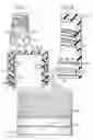
DESCRIPTION OF THE DRAWINGSFIG. 1 is a fragmentary perspective view of a portion of a container embodying the invention.
FIG. 2 is a fragmentary vertical sectional view through 5 the container enclosure embodying the invention;
FIG. 3 is an elevational view of the closure;
FIG. 4 is a fragmentary sectional view of a portion of the closure;
FIG. 5 is a part sectional view of the closure and 10 container;
FIGS. 6 and 7 are partly diagrammatic views showing the steps in the formation of the bridges;
FIG. 8 is a fragmentary view of a portion of a primary knife utilized to form the bridge;
FIG. 9 is a fragmentary sectional view of a portion of a secondary knife for controlling the dimension of the bridges;
FIG. 10 is a plan view of an apparatus for forming the bridges;
FIG. 11 is a fragmentary plan view of the apparatus taken along the line 11-11 in FIG. 10; and
FIG. 12 is a diagram of the relative movements of the closure and knives.
FIG. 13 is a diagram of the relative movements of the closure and knives of a modified method and apparatus.
FIG. 14 is a diagram of the relative movements of the closure and knives of a further modified method and apparatus.
DESCRIPTIONReferring to FIGS. 1-5, the tamper-indicating closure 20 is adapted to be applied to a container 21 and has a tamper-indicating band 22. The closure 20 is made of plastic material such as polypropylene or polyethylene. The closure 20 includes a base wall 23 and peripheral skirt 24 having internal threads 25 adapted to engage external threads 26 on the container 21. A score line 28 extends radially inwardly and circumferentially of the lower portion of the skirt to form the tamper-indicating band 22 having circumferentially spaced bridges 29. The tamper-indicating band 22 includes interengaging means on the band which engages an annular bead or flange on the container to retain the closure on the container.
The interengaging means preferably comprises an annular flange 31 extending axially upwardly and inwardly from the tamper-indicating band toward the base wall of the closure and including a first continuous annular flange portion 32 connected to the band by a hinge portion and a second portion 33, the free edges of which engage beneath bead 30 on the container 21 when the closure 20 is threaded onto the container 21. Such a tamper-indicating closure in one form includes a plurality of segment portions and in another form includes a second continuous flange portion. The flange 31 in both forms is bent intermediate its ends so that the second portion 33 extends inwardly at a greater angle than the first continuous flange portion 32, all as shown in U.S. Pat. No. 5,090,788, incorporated herein by reference. Other types of tamper-indicating bands may also be used as is well known in the art.
The bridges 29 are formed on the closure by rotating the closure relative to a series of knives. As shown in FIG. 6, a primary knife 35 is provided and has an interrupted edge 36 so that when the closure is rolled relatively to the knife 35, a plurality of preformed bridges 29a are provided. The closure is then rotated past a secondary knife 40 that has a continuous edge 41 that extends inwardly of the score formed by the primary knife 35 and cuts the preformed bridges 29a to form rectangular bridges in cross section which have a greater circumferential width than radial thickness. The continuous knife 40 also accurately dimensions the radial thickness of the bridges 29 as shown in FIG. 7. The relative movement of the closure and knives 35, 40 is such that the closure is moved along the edges 36, 41 of the knives 35, 40 and is simultaneously rotated about its axis so that the rate of movement and peripheral rate of rotation are substantially the same.
As shown in FIGS. 8 and 9, the knives 35, 40 preferably have their cutting edges 36, 41 formed with a cross section comprising a cutting edge that has tapered surfaces 37, 42 each of which forms an angle A with the central plane of the knife 35, 40 respectively and tapered surfaces 38, 43 outwardly of the knife edge forming a lesser angle B with the central plane of the knife 35, 40 respectively. In a typical example, knives 35, 40 have an axial thickness of 0.015 in., angle A=18° and angle B=9°.
A typical apparatus for forming the closure is shown in FIGS. 10 and 11 and comprises a mandrel 50 on which the closure is mounted. The mandrel 50 is rotated as well as moved past the knives 35, 40 so that the primary knife 35 forms the preformed bridges 29a and the secondary knife 40 forms the final bridges 29.
Preferably, the mandrel 50 is one of a plurality of mandrels 50 on a turret 51 and the turret 51 is rotated while the mandrels are being rotated about their axes providing a true rolling action of the closure past the knives 35, 40.
As shown in FIGS. 10 and 11, the mandrels 50 are mounted for rotation and vertical movement on the rotating turret 51. A pinion gear 52 on the upper end of each mandrel 50 engages an annular fixed internal gear sector 53. The mandrels 50 are moved vertically into and out of engagement with the inverted closures by a cam follower 54 which follows an annular cam track 55 in a fixed cam above the turret 51.
As shown in FIG. 10, star wheels 57, 58 are provided for feeding and removing the closures 20 from the apparatus.
As further shown in FIG. 10, micrometer screws 59, 60 are provided for accurately positioning knives 35, 40 after which the mounting screws are tightened to lock the knives in adjusted position.
When the closures are moved in an annular path by the turret 51 with the knives 35, 40 positioned radially outwardly of the mandrels 50, the edges 36, 41 of the primary knife 35 and secondary knife 40 extend radially inwardly and are curved in a concave arc parallel to the path of travel of the mandrels 50.
As shown in the diagram, FIG. 12, in this arrangement, the turret 51 is rotating clockwise, as viewed from above, moving the mandrels 50 in a clockwise direction. As the mandrels 50 approach the knives 35, 40 the mandrels 50, and in turn the closures thereon, are rotated counterclockwise by engagement of the pinion gear 52 with the fixed internal gear 53. This provides the desired movement of the closures along the knives 35, 40 and the desired rolling action of the closures relative to the knives 35, 40.
Referring to the diagram shown in FIG. 13, if the knives 35a, 40a are positioned radially inwardly of the mandrels 50, the knives 35a, 40a have edges 36a, 41a which extend radially outwardly and are reversed relative to FIG. 12. In addition, a fixed gear sector 53a having external teeth is positioned radially inwardly for engagement with the pinion gear 52. As a result, the mandrels 50 are rotated clockwise as well as revolved clockwise to obtain the desired movement of the closures along the knives 35a, 40a and the desired rolling action of the closures relative to the knives 35a, 40a.
Referring to FIG. 14, if the mandrels 50 are moved in an endless path which has a straight portion along which the knives are successively positioned, the knives 35b, 40b have straight edges 36b, 41b. The gear sector is a straight fixed rack gear 53b that has teeth which engage the pinion gear 52 on the mandrels. As a result, the mandrels 50 are moved in a straight line past the successive knives 35b, 40b and the mandrels 50 are rotated clockwise to obtain the desired rolling action relative to the knives 35b, 40b.
It can thus be seen that there has been provided a tamper-indicating closure on a molded plastic closure which does not require molded bridges, which can be made by relatively simple less costly molds, wherein the precise configuration of the bridges can be adjusted as desired, and wherein the bridges can be made at relatively high speeds and the desired configuration and strength of the bridges can be maintained, and wherein an improved method and apparatus insure accurately dimensional bridges.
Claims
1. A method of forming a tamper indicating closure from a plastic closure having a base wall and a peripheral skirt, which includes the steps of:
(a) providing a primary cutting knife having an interrupted cutting edge for cutting an interrupted circumferential score, said interrupted circumferential score including circumferentially spaced cuts and a plurality of bridges respectively separating said spaced cuts, said interrupted cutting edge of said primary knife having a cross section with opposed tapered surfaces forming opposite identical angles relative to a plane through the center of said primary cutting knife and intersecting the cutting edge of said knife,
(b) supporting said primary cutting knife in a fixed position on a first support for cutting at a first depth into said peripheral skirt,
(c) providing a secondary cutting knife having a continuous cutting edge for cutting a circumferential score, said continuous cutting edge of said secondary knife having a cross section with opposed tapered surfaces forming opposite identical angles relative to a plane through the center of said secondary cutting knife and intersecting the cutting edge of said secondary cutting knife,
both said primary cutting knife and said secondary cutting knife having said tapered surfaces adjacent to said cutting edges forming an angle A with the central plane of each knife, and both said tapered surfaces spaced from said cutting edges forming an angle B, less than said angle A, with the central plane of each knife,
(d) supporting said secondary cutting knife in a fixed position on a second support for cutting a second depth into said peripheral skirt, said second support means positioning said secondary cutting knife such that said continuous cutting edge is aligned with said interrupted circumferential score,
(e) variably positioning said primary cutting knife on said first support, and variably positioning said secondary cutting knife on said second support independent of said primary cutting knife and said first support, and
(f) moving said plastic closure successively past said primary cutting knife and said secondary cutting knife initially to bring the peripheral skirt of said plastic closure into contact with said interrupted cutting edge of said primary cutting knife to cut said interrupted circumferential score having said plurality of circumferentially spaced bridges, and thereafter to bring said peripheral skirt of said plastic closure into contact with said continuous cutting edge of said secondary cutting knife to cut in and along said interrupted circumferential score to dimension accurately the radial thickness of said bridges.
2. The method set forth in claim 1 wherein said step (f) includes the step of rotating said plastic closure as it is moved past said primary cutting knife and said secondary cutting knife.
3. The method set forth in claim 2 wherein said step (f) includes moving said plastic closure in a straight path, and wherein said primary cutting knife and said secondary cutting knife have straight cutting edges.
4. The method set forth in claim 3 wherein said step (f) includes moving a plurality of said plastic closures by operation of a plurality of mandrels, each mandrel engaging one of said plastic closures for moving each of said plastic closures past the knives.
5. The method set forth in claim 4 wherein said step of rotating said plastic closure is carried out by a pinion gear on each mandrel and a straight fixed rack gear engaging said pinion gear.
6. The method set forth in claim 1 wherein said step (b) includes moving said plastic closure in an arcuate path, and wherein said primary cutting knife and said secondary cutting knife have arcuate cutting edges which conform to said path.
7. The method set forth in claim 6 wherein said step (f) includes moving a plurality of said plastic closures by operation of a turret, having a plurality of mandrels mounted on said turret for movement in a closed path, each mandrel engaging one of said plastic closures and moving each of said plastic closures successively past said primary cutting knife and said secondary cutting knife.
8. The apparatus set forth in claim 7 wherein said step (f) includes the step of rotating each mandrel as it moves said plastic closures past said primary cutting knife and said secondary cutting knife.
9. The method set forth in claim 8 wherein said primary cutting knife and said secondary cutting knife are positioned radially outwardly of said path of the mandrels and wherein said knives have concave cutting edges.
10. The method set forth in claim 9 wherein said step of rotating each mandrel is carried out by a pinion gear on each said mandrel and a gear having internal teeth engaged by said pinion gear such that, when the turret is moved in one direction to move the mandrels and the plastic closures thereon past said knives, the mandrels and the plastic closures are rotated in an opposite direction such that the plastic closures roll relative to said knives.
11. The method set forth in claim 8 wherein said primary cutting knife and said secondary cutting knife are positioned radially inwardly of said path of said mandrels and wherein said knives have convex cutting edges.
12. The method set forth in claim 11 wherein said step of rotating each mandrel is carried out by a pinion gear on each said mandrel and a gear having external teeth engaged by said pinion gear such that, when the turret is moved in one direction to move the mandrels and the plastic closures thereon past said knives, the mandrels and the plastic closures are rotated in the same direction such that the plastic closures roll relative to said knives.
13. The method set forth in claim 1 wherein said angle A is 18° and said angle B is 9°.
14. A method of forming a tamper indicating closure from a plastic closure having a base wall and a peripheral skirt, which includes:
providing a primary arcuate cutting knife having a center of curvature and an interrupted cutting edge for cutting an interrupted circumferential score, said interrupted circumferential score including circumferentially spaced cuts and a plurality of bridges respectively separating said spaced cuts, said interrupted cutting edge of said primary cutting knife having cutting edges formed with a cross section having opposed tapered surfaces each forming an angle relative to a radian through the center of curvature of said arcuate cutting knife and intersecting the cutting edge of said knife,
supporting said primary cutting knife in a fixed position for cutting at a first depth into said peripheral skirt,
providing a secondary arcuate cutting knife having a center of curvature and a continuous cutting edge for cutting a circumferential score,
supporting said secondary cutting knife in a fixed position for cutting at a second depth into said peripheral skirt, and positioning said secondary cutting knife such that said continuous cutting edge is aligned with said interrupted circumferential score, and
each said primary knife and secondary knife having said opposite tapered surfaces, said tapered surfaces adjacent said cutting edge forming an angle A relative to a radian through the center of curvature of said knife and intersecting the cutting edge of said knife, and said tapered surfaces spaced from said cutting edge forming an angle B, less than the angle A, with the central plane of each knife relative to a radian through the center of curvature of said knife and intersecting the cutting edge of said knife,
providing first adjustment means for variably positioning said primary cutting knife on said first support means, and providing second adjustment means for variably positioning said secondary cutting knife on said second support means independent of said first adjustment means on said first support means,
moving said plastic closure successively past said primary cutting knife and said secondary cutting knife to initially bring the peripheral skirt of said plastic closure into contact with said interrupted cutting edge of said primary cutting knife to cut said interrupted circumferential score having said plurality of circumferentially spaced bridges, and to thereafter bring said peripheral skirt of said plastic closure into contact with said continuous cutting edge of said secondary cutting knife to cut in and along said interrupted circumferential score to accurately dimension the radial thickness of said bridges.
15. The method set forth in claim 14 wherein moving said plastic closure includes rotating said plastic closure as it is moved past said primary cutting knife and secondary cutting knife.
16. The method set forth in claim 14 wherein said moving said plastic closure comprises moving said plastic closure in an arcuate path and providing said primary cutting knife and said secondary cutting knife with arcuate cutting edges which conform to said path.
17. The method set forth in claim 16 wherein moving said plastic closure comprises moving a plurality of said plastic closures and comprises providing a turret, and providing a plurality of mandrels mounted for movement in a closed path, each mandrel being adapted to engage one of said plastic closures for moving each of said plastic closures successively past said primary cutting knife and said secondary cutting knife.
18. The method set forth in claim 17 wherein moving said plastic closure includes rotating each mandrel as it moves said plastic closures past said primary cutting knife and said secondary cutting knife.
19. The method set forth in claim 18 including positioning said primary cutting knife and said second cutting knife radially outwardly of said path of the mandrels and providing said knives with concave cutting edges.
20. The method set forth in claim 19 wherein rotating each mandrel comprises providing a pin ion gear on each said mandrel and a gear having internal teeth engaged by said pinion gear such that when the turret is moved in one direction to move the mandrels and the plastic closures thereon past said knives, the mandrels and the plastic closures are rotated in an opposite direction such that the plastic closures roll relative to said knives.
21. The method set forth in claim 18 including positioning said primary cutting knife and said second cutting knife radially inwardly of said path of said mandrels and providing said knives with convex cutting edges.
22. The method set forth in claim 21 wherein rotating each mandrel comprises providing a pinion gear on each said mandrel and a gear having external teeth engaged by said pinion gear such that when the turret is moved in one direction to move the mandrels and in the plastic closures thereon past said knives, the mandrels and the plastic closures are rotated in the same direction such that the plastic closures roll relative to said knives.
23. The method set forth in claim 15 wherein moving said plastic closure to move said plastic closure in a straight path and providing said primary cutting knife and said secondary cutting knife with straight cutting edges.
24. The method set forth in claim 23 wherein moving said plastic closure comprises moving a plurality of said plastic closures and providing a plurality of mandrels, each mandrel being adapted to engage one of said plastic closures for moving each of said plastic closures past the knives.
25. The method set forth in claim 24 wherein rotating said plastic closure comprises providing a pinion gear on each mandrel and providing a straight fixed rack gear engaging said pinion.
Images & Drawings included:


Sources:
- United States Patent and Trademark Office - verify current appl. status at the USPTO↗
Recent applications in this class:
- » 20250249619 2025-08-07
SYSTEMS AND METHODS FOR PERFORATING TEXTILES, INCLUDING CARPET AND RUG UNDERLAYMENT - » 20250249618 2025-08-07
SYSTEMS AND METHODS FOR PERFORATING TEXTILES, INCLUDING CARPET AND RUG UNDERLAYMENT - » 20250196387 2025-06-19
MACHINE AND METHOD FOR APPLYING TUBULAR SHRINK SLEEVE MATERIAL TO OBJECTS - » 20250091243 2025-03-20
METHOD OF PERFORATING A NONLINEAR LINE OF WEAKNESS - » 20240359354 2024-10-31
A ROTATING BLADE DEVICE, A MACHINE COMPRISING SAID DEVICE, AND METHOD - » 20240149485 2024-05-09
ELECTRODE PLATE SLITTING CUTTER HOLDER AND ELECTRODE PLATE SLITTING MACHINE - » 20230364820 2023-11-16
Method of perforating a nonlinear line of weakness - » 20220332006 2022-10-20
Method of perforating a nonlinear line of weakness - » 20220184841 2022-06-16
PATCH DEVICES, METHODS AND APPARATUS FOR FORMING, AND TESTING PHARMACEUTICAL AGENT DELIVERY PATCH DEVICES - » 20210187776 2021-06-24
Apparatus for perforating a nonlinear line of weakness
Recent applications for this Assignee:
- » 20050031730 2005-02-10
Apparatus for introducing plastic material into an annular mold cavity - » 10763636 2005-09-27
Fill-through container and closure package - » 10648979 2006-05-09
Method of making a dispensing closure - » 10646481 2005-07-05
Plastic closure with compression molded layered barrier liner - » 10446411 2005-11-29
Tamper-indicating closure with lugs on a stop flange for spacing the flange from the finish of a container - » 10384945 2006-04-04
Plastic closure with compression molded sealing/barrier liner - » 10375738 2005-08-23
Toggle-action dispensing closure, package and method of making - » 10287841 2005-05-24
Self-closing fluid dispensing closure - » 10252918 2006-03-07
Urine collection method and apparatus - » 10252917 2005-04-19
Dispensing closure, package and method of manufacture