Hydroelectric turbine
US20050031442A1
2005-02-10
10/633,865
2003-08-05
✅ Patent granted
US 6,957,947 B2
2005-10-25
-
-
Edward K. Look
2023-08-05
Abstract:
A hydroelectric turbine anchored in a body of water which produces electricity directly from its housing. The turbine is in and of itself a generator whose housing is its stator and whose blade it its rotor.
Interested in similar patents?
Get notified when new applications in this technology area are published.
Classification:
H02K7/1823 » CPC main
Arrangements for handling mechanical energy structurally associated with dynamo-electric machines, e.g. structural association with mechanical driving motors or auxiliary dynamo-electric machines; Structural association of electric generators with mechanical driving motors, e.g. with turbines; Rotary generators structurally associated with turbines or similar engines
F03B11/06 » CPC further
Parts or details not provided for in, or of interest apart from, the preceding groups e.g. wear-protection couplings, between turbine and generator , Bearing arrangements
F03B17/061 » CPC further
Other machines or engines using liquid flow , e.g. of swinging-flap type with rotation axis substantially in flow direction
Y02E10/20 » CPC further
Energy generation through renewable energy sources Hydro energy
Y02E10/20 » CPC further
Energy generation through renewable energy sources Hydro energy
Y10S415/908 » CPC further
Rotary kinetic fluid motors or pumps; Natural fluid current motor Axial flow runner
Y10S416/04 » CPC further
Fluid reaction surfaces, i.e. impellers Fluid current motor and generator
Description
CROSS-REFERENCE TO RELATED APPLICATIONS“Not Applicable”
STATEMENT REGARDING FEDERALLY SPONSORED RESEARCH OR DEVELOPMENT“Not Applicable”
REFERENCE TO A MICROFICHE APPENDIX“Not Applicable”
BACKGROUND OF THE INVENTIONIn existing hydro systems, whether low or high head, the runner (or blade) converts rotational energy to torque energy in a shaft. U.S. Pat. No. 98,552 is a common type shaft driven turbine. Patent Ser. No. 09/231,063 is a more recent open center, peripherally driven turbine. The embodiment eliminates the shaft. It converts flow energy directly to electricity by the use of magnets imbedded in the periphery of its blade and cores imbedded in its housing. As the blade is rotated by the flow, electricity is produced in the windings of the core.
The embodiment is a combination of what is old (the open center turbine) and what is new (a free floating turbine blade which is a rotor).
BRIEF SUMMARY OF THE INVENTIONPresent turbine designs, whether open center or central shaft type, produce electricity by the use of generators. This invention produces electricity by combining the turbine and generator in one unit. Instead of the hydroelectric turbine producing the energy to turn a generator, the hydroelectric turbine is the generator.
A water flow through the rotor blade causes the rotor blade to rotate. The rotation of the blade causes a magnetic field necessary to produce electricity from the coils. The coils are connected together in such a way as to produce the desired voltage and current to pass through conductors to an electrical land based grid.
The opposing force of one group of magnets aid in maintaining alignment of the rotor blade on its horizontal axis.
The opposing force of another group of magnets, in conjunction with a water lubricated bearing material, aid in preventing the rotor blade from being forced downstream.
An additional aspect of the embodiment is that the rotor (blade) is free floating in the turbine housing and is not mechanically attached to the housing. Central alignment has been achieved by embedding opposing magnets in both the blade periphery and the housing interior on a plane perpendicular to the axis of the turbine. To prevent the blade from being forced downstream by the water flow, opposing magnets have been embedded in the blade periphery and the housing parallel to the axis. To prevent the blade from moving forward or falling out of the housing during shut down or maintenance, stops are mechanically attached to the interior of the housing upstream of the blade.
The magnetic field necessary to produce electricity occurs inside a non-magnetic material which:
- a. eliminates excessive saltwater which is not compatible with the high intensity magnetic field necessary for the production of electricity;
- b. acts as a bearing surface to help maintain horizontal alignment of the blade (rotor).
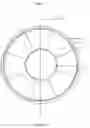
FIG. 1 is a front view of the open center hydroelectric turbine without stops (for sake of clarity).
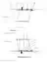
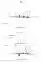
FIG. 2 is a cross-section view taken at the centerline of the turbine section.
DETAILED DESCRIPTION OF THE INVENTIONThe housing (1) is either anchored in a body of water (low head application), fixed in a dam (high head application) or attached to the interior of a pipe. Whatever the application, housing (1) is stationary.
The outer rim (2), blade (3), inner rim (4), magnet (6), magnet (8) and magnet (9) are fixed as one unit and rotated by the water flow.
The magnet (6) and core with windings (5) do the work of producing electricity.
The magnets (8) and (7) do the work of alignment to the axis.
The magnets (9) and (10) prevent blade (3) from being pushed downstream by the water flow.
The stop (11) prevents the runner from moving upstream.
Claims
1. A hydroelectric turbine whose only moving part is its rotor blade.
2. A hydroelectric turbine of claim 1 which produces electricity without the use of a central shaft or generator.
3. A hydroelectric turbine of claim 1 which produces electricity without being mechanically attached to a generator.
4. A hydroelectric turbine of claim 1 whose blade is its rotor.
5. A hydroelectric turbine of claim 1 whose housing is its stator.
6. A hydroelectric turbine of claim 1 whose stator (housing) and rotor (blade) does the work of generating electricity.
7. A hydroelectric turbine whose blade is not mechanically connected to it.
8. A method of claim 2 using magnets and a water lubricated bearing material to prevent the rotor blade of a hydroelectric turbine from contacting its housing.
9. A hydroelectric turbine of claim 2 whose blade is held on location within its housing by the use of magnets.
10. A hydroelectric turbine which utilizes both magnets and a water lubricated bearing to maintain alignment of its rotor.
11. A method of claim 3 of using magnets to prevent the blade of a hydroelectric turbine from being forced downstream.
12. A hydroelectric turbine of claim 3 which has a water lubricated bearing surface attached to the interior of its stator which aids in the alignment of its rotor.
13. A hydroelectric turbine of claim 3 which has no central shaft and uses both magnets and water lubricated bearings to maintain alignment of its rotor.
14. A hydroelectric turbine of claim 3 which has a water lubricated bearing material mechanically attached to its housing to aid magnets in maintaining alignment of its horizontal axis.
15. A hydroelectric turbine of claim 3 which utilizes both magnets and a water lubricated bearing to prevent the rotor blade from being forced downstream.
16. A hydroelectric turbine which has no central shaft and whose blade is its rotor and whose housing is its stator.
17. A method of using magnets to align a rotor blade of a hydroelectric turbine on its horizontal axis.
18. A method of maintaining the clearance between the stator and rotor of a hydroelectric turbine by the use of magnets and a water lubricated non-magnetic bearing material.
19. A hydroelectric turbine of claim 6 which has magnets embedded in and mechanically attached to the periphery of the turbine blade which is rotated by a water flow.
20. A method of reducing friction between the stator and rotor of a hydroelectric turbine of claim 6 consisting of using a water lubricated bearing material on the stator arranged to contact a metallic or porcelain surface on the rotor when out of horizontal alignment occurs with the rotor.
21. A hydroelectric turbine of claim 6 which does not use a central shaft to maintain alignment of its rotor within the stator.
22. A method of claim 6 requiring the magnetic field necessary to produce electricity to take place within a non-magnetic bearing material in order to displace saltwater.
23. A hydroelectric turbine which uses three distinctly separate groups of magnets:
one group of magnets arranged to produce the magnetic field necessary to produce electricity;
one group of magnets arranged similar poles facing each other to maintain alignment of the rotor;
and, one group of magnets arranged similar poles facing each other to prevent the rotor from being forced downstream by the force of the water against the rotor.
24. A method of producing electricity from the stator housing of a hydroelectric turbine.
25. A method of displacing saltwater thru the use of a non-magnetic bearing material.
Images & Drawings included:
Sources:
- United States Patent and Trademark Office - verify current appl. status at the USPTO↗
Similar patent applications:
- » 20090179426
Reduced pressure differential hydroelectric turbine system - » 20090278357
Tidal flow hydroelectric turbine - » 17835939
Systems and processes for pipeline transport of water using micro hydroelectric turbines to reduce electricity drawn from third-party electrical power grids - » 20070018459
Hydroelectric turbine and method for producing electricity from tidal flow - » 20070018460
Tidal flow hydroelectric turbine - » 13665683
Hydroelectric turbine system and method of manufacture - » 20050029817
Gimbal-mounted hydroelectric turbine - » 20080296900
Spillway hydroelectric turbine - » 20090160193
BENKATINA HYDROELECTRIC TURBINE - » 20100025998
Submerged hydroelectric turbines having buoyancy chambers
Recent applications in this class:
- » 20250286435 2025-09-11
DECENTRALIZED RENEWABLE POWER GENERATION AND METHODS FOR UNIVERSAL BASIC INCOME - » 20250233481 2025-07-17
THREE-PHASE ELECTRICAL GENERATOR - » 20250219506 2025-07-03
SYSTEM USING COLD HEAT - » 20250175058 2025-05-29
INTEGRATED GENERATOR/CONVERTER FOR TURBINE APPLICATIONS - » 20250141305 2025-05-01
FITTING - » 20250132637 2025-04-24
AXIAL BRUSHLESS MOTOR GENERATOR - » 20250112523 2025-04-03
MAGNET RETENTION IN EXTERIOR ROTOR ELECTRIC MACHINES - » 20250079936 2025-03-06
Electromagnetic Combo Machine and Method For Use in Downhole Applications - » 20250070616 2025-02-27
Systems and methods for producing clean energy - » 20250038618 2025-01-30
Mobile Electric Power Generation for Hydraulic Fracturing of Subsurface Geological Formations