Cabinet having an assembling structure
US20050035697A1
2005-02-17
10/643,113
2003-08-13
Abstract:
A cabinet includes two side plates and one or more rear plates each having a channel formed by a flap, an upper plate secured on top of the side plates and the rear plates, an upper and a lower beams secured between front portions of the side plates, and a bottom plate having two side flanges and a rear flange extended downwardly to engage into the channels of the side plates and the rear plates, and to latch and secure the bottom plate to the side plates and the rear plates. Each of the flanges of the bottom plate may further include one or more catches to engage into the flaps and to solidly secure the bottom plate to the side plates and the rear plates.
Interested in similar patents?
Get notified when new applications in this technology area are published.
Classification:
A47B47/02 » CPC main
Cabinets, racks or shelf units, characterised by features related to dismountability or building-up from elements made of metal only
Description
BACKGROUND OF THE INVENTION1. Field of the Invention
The present invention relates to a cabinet, and more particularly to a cabinet having a structure to be easily assembled by the users themselves.
2. Description of the Prior Art
Typical cabinets, particularly the metal cabinets comprise a parallelepiped structure formed by a bottom plate, two side plates, one rear plate, a top plate, and two doors open ably attached to the front portion of the side and top and bottom plates, and one or more shelves selectively attached between the side plates.
The side and top and bottom plates of the typical cabinets are normally welded together or solidly secured together such that the typical cabinets comprise a large volume that is adverse for storing and transportation purposes. The typical metal cabinets may not be assembled by the users themselves.
The present invention has arisen to mitigate and/or obviate the afore-described disadvantages of the conventional cabinets.
SUMMARY OF THE INVENTIONThe primary objective of the present invention is to provide a cabinet including a structure to be easily assembled by the users themselves, to allow the cabinet to be disassembled to compact folding structure or a compact volume that is excellent for storing and transportation purposes.
In accordance with one aspect of the invention, there is provided a cabinet comprising two side plates each including a lower portion having a channel formed therein, at least one rear plate including a lower portion having a channel formed therein, an upper plate secured on top of the side plates and the rear plate, an upper and a lower beams secured between front portions of the side plates respectively, and a bottom plate including two side flanges and a rear flange extended downwardly therefrom and engageable into the channels of the side plates and the rear plate, to latch and secure the bottom plate to the side plates and the rear plate.
Each of the side plates includes a front and a rear posts each having a first panel perpendicular to the side plates and a second panel parallel to the side plates respectively. Each of the bottom plate includes four corner notches to receive the front and the rear posts of the side plates respectively.
Each of the first panels of the front and the rear posts of the side plates includes a plurality of slots formed therein, the cabinet further includes a plurality of hooks engaged to the slots respectively, and at least one shelf selectively engaged and supported on the hooks respectively.
Each of the rear posts of the side plates includes at least one groove formed therein, the rear plate includes at least one ear extended therefrom to engage into the groove of each of the side plates, and to latch the rear plate between the side plates.
Each of the upper and the lower beams includes two extensions extended therefrom and engaged with and secured to the front posts, to secure the upper and the lower beams between the side plates. The lower beam includes a fence extended upwardly therefrom, the bottom plate includes a front flange extended downwardly therefrom and engageable with the fence of the lower beam, to latch and secure the bottom plate to the lower beam.
Each of the side plates and the rear plate includes a flap secured thereto to define the channel thereof respectively. Each of the flaps includes a lower segment secured to the side plates and the rear plate to define the channel between the flaps and the side plates and the rear plate respectively.
Each of the flaps includes at least one opening formed therein, each of the side flanges and the rear flange of the bottom plate includes at least one catch extended therefrom to engage into the opening of the flaps respectively, and to solidly secure the side flanges and the rear flange of the bottom plate to the side plates and the rear plate respectively.
A track may further be provided and secured on top of the lower beam, and two sliding door panels slidably engaged on the track. The rear plate includes a lever provided on top thereof, the upper plate includes at least one flap extended downwardly therefrom to form a space therein, and to receive the lever of the rear plate.
A drawer may further be provided and slidably received therein. The side plates includes a rail secured thereto, and a sliding member slidably received in the rail respectively and secured to the drawer, to slidably support the drawer to the rails.
Further objectives and advantages of the present invention will become apparent from a careful reading of the detailed description provided herein below, with appropriate reference to the accompanying drawings.
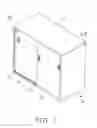
BRIEF DESCRIPTION OF THE DRAWINGSFIG. 1 is a perspective view of a cabinet in accordance with the present invention;
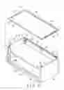
FIG. 2 is an exploded view of the cabinet;
FIGS. 3, 4, 5, 6 are partial exploded views illustrating the assembling operation of the cabinet;
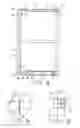
FIG. 7 is a top plan view of the cabinet, having an upper plate removed from the cabinet to show the inner structure of the cabinet;
FIG. 8 is a partial cross sectional view taken along lines 8-8 of FIG. 1;
FIGS. 9, 10 are enlarged partial cross sectional views of the cabinet;
FIG. 11 is a perspective view illustrating the other arrangement of the cabinet;
FIGS. 12, 13, 14 are partial exploded views of the cabinet as shown in FIG. 11;
FIG. 15 is an enlarged partial plan schematic view illustrating the coupling of the side and rear plates of the cabinet;
FIGS. 16, 17, 18 are partial exploded views of the cabinet as shown in FIGS. 11-13; and
FIGS. 19, 20 are perspective views illustrating the other embodiments of the cabinet.
DETAILED DESCRIPTION OF THE PREFERRED EMBODIMENTReferring to the drawings, and initially to FIGS. 1-10, a cabinet in accordance with the present invention comprises two side plates 10 each including a front and a rear posts 11, 12 each defined by a first panel 13 perpendicular to the side plates 10 and a second panel 14 extended from the first panel 13 and parallel to the side plates 10. Each of the rear posts 12 of the side plates 10 includes one or more grooves 15 formed therein, and preferably formed between the first and the second panels 13, 14 (FIGS. 2-4).
Each of the first panels 13 of the front and the rear posts 11, 12 includes a number of slots 16 formed therein to receive or support a number of hooks 17 respectively. One or more shelves 18 may be optionally or selectively engaged onto the hooks 17 which may thus support the shelves 18 between the front and the rear posts 11, 12 of the side plates 10, and thus between the side plates 10, in order to support various objects on the shelves 18. Each of the side plates 10 includes an upwardly extended upper flange 19.
Two front and lateral beams 20 each includes two extensions 21 extended from the ends thereof respectively, and engaged with and secured to the first panels 13 of the front posts 11 with fasteners 22 or the like, so as to secure the beams 20 between the upper and the lower portions of the front portions of the side plates 10 (FIG. 3) respectively. The lower beam 20 includes a fence 23 extended upwardly from the rear portion thereof. A track 24 is secured on the lower beam 20 to slidably support two door panels 25. Alternatively, the door panels 25 may be pivotally secured to the front portion of the side plates 10 (FIG. 20).
One or more, such as two rear plates 30 each includes one or more ears 31 extended therefrom, for engaging into the grooves 15 of the rear posts 12 of the side-plates 10, in order to latch or secure the rear plates 30 between the side plates 10. One of the rear plates 30 includes a board 33 extended therefrom and engageable onto one side or an inner side portion 32 of the other rear plate 30, and a hook 34 extended from the board 33 and engaged with the inner side portion 32 of the other rear plate 30, to hook and secure the rear plates 30 together (FIGS. 4-6).
Each of the side plates 10 and the rear plates 30 includes a lower portion having a flap 35 secured thereto. For example, each of the flaps 35 includes a lower segment 36 secured to the lower portion of the respective side and the rear plates 10, 30, so as to form or define a channel 37 between the flap 35 and the respective side and the rear plates 10, 30. Each of the flaps 35 includes one or more openings 38 formed therein. Each of the rear plates 30 includes a lever 39 provided on top thereof.
A bottom plate 40 includes four flanges 41, such as two side flanges 41 and a front and a rear flanges 41 extended downwardly from the four sides thereof respectively, and engaged into the channels 37 defined between the respective flaps 35 and the side and the rear plates 10, 30, such that the bottom plate 40 may be easily and quickly secured between the side and the rear plates 10, 30. It is preferable that each of the four flanges 41 of the bottom plate 40 includes one or more catches 42 (FIG. 9) extended therefrom and engaged into the openings 38 of the flaps 35, to further solidly secure the bottom plate 40 between the side and the rear plates 10.
The bottom plate 40 includes four corner notches 43 formed therein to receive the front and the rear posts 11, 12 respectively, and another notch 44 formed therein to receive the board 33 and the hook 34 of the rear plates 30, best shown in FIG. 7. It is preferable that the bottom plate 40 includes one or more reinforcing stays 46 (FIG. 8) secured to the bottom thereof, to reinforce the bottom plate 40 and to prevent the bottom plate 40 from being deformed by the objects supported on the bottom plate 40.
An upper plate 60 includes two side slits 61 formed therein to receive the upwardly extended upper flanges 19 of the side plates 10, and thus to latch and secure the upper plate 60 onto the side plates 10. The upper plate 60 includes one or more, such as two flaps 62 extended downwardly from the rear portion thereof, each to form or define a space 63 therein (FIG. 10), and to receive the levers 39 of the rear plates 30, and to further solidly secure the levers 39 of the rear plates 30 to the flaps 62 of the upper plate 60 with one or more fasteners 64 (FIGS. 8, 10).
As shown in FIGS. 3-7, a number of pads or stops 66 each includes a pin 67 extended therefrom and engaged into the upper portions of the respective panels 14 of the front posts 11, and engageable with the upper beam 20 and/or the upper plate 60, in order to solidly support the upper beam 20 and/or the front portion of the upper plate 60 on the front posts 11. As shown in FIGS. 1, 2, 6, 8, the upper plate 60 may include a front flange 68 extended downwardly from the front portion thereof, to engage with and/or to cover or shield the upper beam 20.
As shown in FIGS. 11-18, illustrated is the other arrangement of the cabinet. The side plates 10 and/or the rear plates 30 may each include one or more catches 70 extended from the upper portion thereof, and the upper plate 60 may include a number of downwardly extended flaps 62 each having one or more openings 65 formed therein (FIGS. 13, 14) to receive the catches 70 and to latch and secure the upper plate 60 to the side and the rear plates 10, 30.
The front flange 68 of the upper plate 60 may include a cavity 69 formed therein to receive a lock 71 therein. The side and the rear plates 10, 30 may be solidly secured together with a hooking structure 72, best shown in FIGS. 12-15. As shown in FIG. 16, four angles 73 may be secured to the corners of the side and the rear plates 10, 30, and/or the bottom plate, in order to maintain the cabinet in the parallelepiped structure.
Two poles 26 may further be provided and secured between the beams 20, and each of the poles 26 may include one or more orifices 27 formed therein. A column 28 is attached to one of the poles 26, and includes one or more pegs 29 extended therefrom and engaged through the orifices 27 of the one pole 26.
As shown in FIGS. 12 and 17-18, one or more pairs of rails 74 may further be provided and secured to the side plates 10, or each may include one or more hooks 75 provided on one end thereof to engage into the orifices 27 of the other pole 26, and a key 76 extended from the other end thereof, to engage into the corresponding slots 77 of the rear plates 30 and/or the side plates 10, and to secure the rails 74 to the side plates 10 and/or the rear plates 30. One or more pairs of sliding members 78 are slidably received in the rails 74 respectively to support one or more drawers 80 within the cabinet.
Each of the drawers 80 may include a bottom board 81, two side boards 82, a front board 83 and a rear board 84 secured together with such as engagements of tongues 85 and slots 86 thereof, and/or fasteners, or the like, and may further include an inner board 87 secured to the front board 83 with fasteners or the like. The drawers 80 may be secured to the sliding members 78, in order to be slidably secured to the rails 74. The lock 71 may be used to lock the drawers 80 to the side plates 10 and/or the upper plate 60.
The cabinet may be arranged to various structures, and may include, for example, a single story having two sliding door panels 25, as shown in FIG. 1, or having two pivotal or openable door panels 25, as shown in FIG. 20; or may include one or more stories each having a drawer 80 slidably received therein (FIG. 11); or may include two or more stories each having two pivotal or openable door panels 25 or each having two sliding door panels 25, as shown in FIG. 19.
Accordingly, the cabinet in accordance with the present invention includes a structure to be easily assembled by the users themselves, to allow the cabinet to be disassembled to compact folding structure or a compact volume that is excellent for storing and transportation purposes.
Although this invention has been described with a certain degree of particularity, it is to be understood that the present disclosure has been made by way of example only and that numerous changes in the detailed construction and the combination and arrangement of parts may be resorted to without departing from the spirit and scope of the invention as hereinafter claimed.
Claims
1. A cabinet comprising:
two side plates each including a lower portion having a channel formed therein,
at least one rear plate including a lower portion having a channel formed therein,
an upper plate secured on top of said side plates and said at least one rear plate,
an upper and a lower beams secured between front portions of said side plates respectively, and
a bottom plate including two side flanges and a rear flange extended downwardly therefrom and engageable into said channels of said side plates and said at least one rear plate, to latch and secure said bottom plate to said side plates and said at least one rear plate.
2. The cabinet as claimed in claim 1, wherein each of said side plates includes a front and a rear posts each having a first panel perpendicular to said side plates and a second panel parallel to said side plates respectively.
3. The cabinet as claimed in claim 2, wherein each of said bottom plate includes four corner notches to receive said front and said rear posts of said side plates respectively.
4. The cabinet as claimed in claim 2, wherein each of said first panels of said front and said rear posts of said side plates includes a plurality of slots formed therein, said cabinet further includes a plurality of hooks engaged to said slots respectively, and at least one shelf selectively engaged and supported on said hooks respectively.
5. The cabinet as claimed in claim 2, wherein each of said rear posts of said side plates includes at least one groove formed therein, said at least one rear plate includes at least one ear extended therefrom to engage into said at least one groove of each of said side plates, and to latch said at least one rear plate between said side plates.
6. The cabinet as claimed in claim 1, wherein each of said upper and said lower beams includes two extensions extended therefrom and engaged with and secured to said front posts, to secure said upper and said lower beams between said side plates.
7. The cabinet as claimed in claim 1, wherein said lower beam includes a fence extended upwardly therefrom, said bottom plate includes a front flange extended downwardly therefrom and engageable with said fence of said lower beam, to latch and secure said bottom plate to said lower beam.
8. The cabinet as claimed in claim 1, wherein each of said side plates and said at least one rear plate includes a flap secured thereto to define said channel thereof respectively.
9. The cabinet as claimed in claim 8, wherein each of said flaps includes a lower segment secured to said side plates and said at least one rear plate to define said channel between said flaps and said side plates and said at least one rear plate respectively.
10. The cabinet as claimed in claim 8, wherein each of said flaps includes at least one opening formed therein, each of said side flanges and said rear flange of said bottom plate includes at least one catch extended therefrom to engage into said at least one opening of said flaps respectively, and to solidly secure said side flanges and said rear flange of said bottom plate to said side plates and said at least one rear plate respectively.
11. The cabinet as claimed in claim 1 further comprising a track secured on top of said lower beam, and two sliding door panels slidably engaged on said track.
12. The cabinet as claimed in claim 1, wherein said at least one rear plate includes a lever provided on top thereof, said upper plate includes at least one flap extended downwardly therefrom to form a space therein, and to receive said lever of said at least one rear plate.
13. The cabinet as claimed in claim 1 further comprising a drawer slidably received therein.
14. The cabinet as claimed in claim 13, wherein each of said side plates includes a rail secured thereto, and a sliding member slidably received in said rail respectively and secured to said drawer, to slidably support said drawer to said rails.
15. A cabinet comprising:
two side plates,
a first and a second rear plates,
an upper plate secured on top of said side plates and said first and said second rear plates, and
a bottom plate secured to said side plates and said first and said second rear plates,
said first rear plate includes an inner side portion, said second rear plate includes a board extended therefrom and engageable onto said inner side portion of said first rear plate and includes a hook extended from said board and engaged with said inner side portion of said first rear plate, to hook and secure first and said second rear plates together.
16. The cabinet as claimed in claim 15, wherein each of said first and said second rear plates includes a flap secured thereto to define a channel therein, said bottom plate includes two rear flanges extended downwardly therefrom and engageable into said channels of said first and said second rear plates, to latch and secure said bottom plate to said first and said second rear plates.
17. The cabinet as claimed in claim 15, wherein said bottom plate includes a notch formed therein to receive said board and said hook of said second rear plate.
Images & Drawings included:


Sources:
- United States Patent and Trademark Office - verify current appl. status at the USPTO↗
Similar patent applications:
- » 20120229008
Cabinet structure assembly - » 20120229009
CABINET STRUCTURE ASSEMBLY - » 20110266936
Motorized moveable shelf assembly for cabinet structures - » 20080297013
Assembly structure of a cabinet and thin display device - » 20220394867
Device having fool-proofing structure and cabinet type device assembly - » 20240175290
HANDLE SYSTEM FOR VERTICAL DRAWER, CABINET STRUCTURE PROVIDED WITH SUCH SYSTEM, KIT FOR ASSEMBLING THE SAME, AND CORRESPONDING METHODS OF MANUFACTURING, ASSEMBLING AND OPERATING ASSOCIATED THERETO
Recent applications in this class:
- » 20250024939 2025-01-23
EMERGENCY RESPONSE LOCKER - » 20190374027 2019-12-12
Locker with solid surface panels having embedded structural reinforcing - » 20190191871 2019-06-27
Modular cabinet design - » 20180344027 2018-12-06
Magnetically Attached Removable Tabletop - » 20140009046 2014-01-09
CABINET WITH A ROLL DOOR - » 20120118837 2012-05-17
Equipment rail and bracket assembly - » 20100282629 2010-11-11
Side cabinet and hutch system - » 20090243444 2009-10-01
Storage unit - » 20090102337 2009-04-23
Side cabinet and hutch system - » 20080297015 2008-12-04
STORAGE UNIT BACK STOP AND METHOD