Device and method for triggering a sensor for cables
US20050109594A1
2005-05-26
10/954,369
2004-10-01
✅ Patent granted
US 7,202,796 B2
2007-04-10
-
-
Daniel Wu | Lam Pham
2025-02-04
Abstract:
In order to provide a triggering signal for an insulating device that is also capable of dealing with very thin wires, it is suggested to use a piezoelectric sensor (10), the output signal from which is forwarded to an electronic evaluation unit (20). The electronic evaluation unit (20) then outputs a digital signal that enables the insulation process to be started safely. Various mechanical means are suggested to ensure that the digital signal is not triggered when not being touched. This problem is proposed to be solved by a low pass filter discriminating between sensor inputs by touching and vibration shock events, etc.
Assignee:
- KOMAX HOLDING AG 120 🇨🇭 Dierikon, Switzerland
Interested in similar patents?
Get notified when new applications in this technology area are published.
Classification:
G08B21/00 IPC
Alarms responsive to a single specified undesired or abnormal condition and not otherwise provided for
G01R19/00 IPC
Arrangements for measuring currents or voltages or for indicating presence or sign thereof
H02G3/04 IPC
Installations of electric cables or lines in or on buildings, equivalent structures or vehicles; Details Protective tubings or conduits or channels or other supports
G01L1/00 IPC
Measuring force or stress, in general
H02G1/1248 » CPC main
Methods or apparatus specially adapted for installing, maintaining, repairing or dismantling electric cables or lines for removing insulation or armouring from cables, e.g. from the end thereof by cutting and withdrawing insulation Machines
Description
FIELD OF THE INVENTIONThe present invention relates to a device for triggering a signal indicating that a cable end has reached a given position relative to its linear movement. The invention further relates to a method for triggering such a sensor.
BACKGROUND OF THE INVENTIONPrior Art
In the field of cable assembly, particularly during the automated insulation of conductors, technicians are familiar with the problem of ensuring that the cable end triggers a signal when it reaches a given advanced position during insertion into an insulating arrangement, and the need to find a method for achieving this. Accordingly, solutions including a mechanical triggering sensor have been disclosed in suggestions such as U.S. Pat. No. 4,745,828. According to that approach the end of the conductor that is to be insulated is moved towards a mechanical triggering sensor—known in this case as a pick-up—until the sensor is actuated, then end of the conductor is immobilized in position by means of gripping jaws and the end of the conductor is incised in known manner for purposes of insulation.
For conductors having a certain diameter and the associated triggering force, the pick-up suggested in the document cited above, together with its limit stop, is also entirely capable of responding to the sensor technology and triggering the immobilisation and insulating process. However, problems have been encountered with conductor ends having very small diameters and the associated low triggering force, and it is these problems that are addressed by the present invention.
SUMMARY OF THE INVENTIONThe object of the invention is thus to provide a sensor and an associated triggering mechanism for use particularly even with very thin conductor ends which do not exert sufficient force to actuate a mechanical trigger. The sensor may also be designed to serve as a mechanical limit stop.
The invention solves its object with a device for detecting a limit position of a conductor end during lengthwise advancement, including a piezoelectric sensor element delivering an electrical output signal which sensor element is arranged essentially perpendicularly to the direction of advancement, and an electronic evaluation unit that receives the electrical output signal from the piezoelectric sensor element in input signal and outputs a triggering signal as a function of its input signal.
The primary result of the invention is that even very thin conductor ends may be detected with the suggested sensor, without limiting the device to use exclusively with very thing conductors. The sensor is arranged in such manner that it may be moved away from the operating area to allow further operations.
Surprisingly, it has been found that a simple digitising circuit is sufficient for use as the electronic triggering unit, that is to say the electronic evaluation unit. Preferred, however, is the invention performed by preparing the current delivered by the sensor to the microprocessor by means of an current amplifier, a low pass filter and a precision rectifier in order to discriminate between touching of the sensor and vibration shock, e.g. from the environment.
According to another aspect of the invention a method for detecting a limit position of a conductor end during lengthwise advancement, including a piezoelectric sensor element arranged essentially perpendicularly to the direction of advancement, and an electronic evaluation unit, comprising the steps of advancing the conductor end as far as the piezoelectric sensor element to trigger a measurement signal, directing the electrical output signal from the piezoelectric sensor element to the electronic evaluation unit as an input signal, and outputting a triggering signal as a function of the input signal is proposed. This method is advantageous for triggering the immobilising and gripping mechanism for the conductor end to be insulated.
Additional advantageous features of the invention are explained in the dependent claims.
The elements that have been listed in the preceding and the use of which according to the invention is claimed and described in the following embodiments are not subject to any particular exceptional conditions in terms of their size, shape, constituent materials or technical design, which means that the generally known selection criteria may be applied in their respective fields of use.
Further details, features and advantages of the object of the invention will become apparent from the following detailed description of the associated drawing, in which—for exemplary purposes—a device and an associated process sequence is explained for the present invention.
BRIEF DISCUSSION OF THE DRAWINGSIn the drawing:
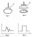
FIG. 1 represents a typical piezoelectric element,
FIG. 2 represents the element of FIG. 1 in which the housing is shown separated from the actual sensor,
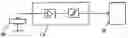
FIG. 3a represents the device as a whole including the piezoelectric sensor, the electronic evaluation unit, and pick-ups for the digital triggering signal to being the insulation process, according to a first embodiment of the invention,
FIG. 3b represents the device as a whole including the piezoelectric sensor, the electronic evaluation unit, and pick-ups for the digital triggering signal to being the insulation process, according to a second, preferred embodiment of the invention,
FIG. 4 is a typical signal from the piezoelectric element after it has been touched by a thin wire,
FIG. 5 is the digital signal created from the signal according to FIG. 4,
FIG. 6 is a diagram according to FIG. 5, with a scale, and
FIG. 7 is a diagram according to FIG. 6, with a scale.
DESCRIPTION OF THE PREFERRED EMBODIMENTS OF THE INVENTIONThe device according to the invention, which is designated integrally in FIG. 3a with the number 100, represents one of the preferred embodiments, and essentially includes a piezoelectric sensor element 10 in a housing and an electronic evaluation unit 20. In the embodiment described in the following, a piezoelectric element produced by Stelco (type SS 11-J9-000) is used, but any element having equivalent performance characteristics may be used instead.
According to the embodiment, piezoelectric sensor element 10 is arranged such that the conductor end comes into essentially perpendicular contact with the actual sensor. FIG. 4 represents a typical signal that is emitted by the piezoelectric sensor element when the conductor end comes into contact with it.
Electronic evaluation unit 20, which is powered electrically by a 24 V power unit, now emits a digital signal (typically: Schmidt trigger) with standard height and width.
FIG. 6 shows the output signal from piezoelectric sensor element 10 as it appears on an oscilloscope. From this it is evident that a post-pulse oscillation is triggered when sensor element 10 is contacted by the conductor end, and must be standardised by electronic evaluation unit 20. The output signal from electronic evaluation unit 20 is shown in FIG. 7.
In the first embodiment show as a typical embodiment, the output signal from electronic evaluation unit 20 is sent to an interface card 30 of the insulation device. The advantage of this arrangement is that the device described here may be replaced as a unit by a conventional mechanical device (such as the one proposed in U.S. Pat. No. 4,745,828) or also by an optical triggering device, if only one similar digital signal is provided in each case.
In this exemplary embodiment, the circuitry for electronic evaluation unit 20 is configured such that it does not accept another signal from the piezoelectric sensor element for a defined time (e.g. 250 ms.) after the triggering process. On the other hand however, an additional input may also be provided to the electronic evaluation unit, which—additionally if necessary—blocks the electronic evaluation unit while the insulation process is being performed, until the insulated conductor end is ejected from the insulating device. These blocking means render inadvertent triggering highly unlikely.
In the more preferred embodiment according to FIG. 3b, of the current signal delivered by the piezoelectric sensor is prepared by electronic means in order to have a signal usable for the microprocessor. The electronic comprise a current amplifier, a low pass filter and a precision rectifier. This electronic means are dimensioned so that any signals generated by vibration shocks etc. not initiated by a touching of the sensor are suppressed.
Claims
1. A device for detecting a limit position of a conductor end during lengthwise advancement,
including a piezoelectric sensor element delivering an electrical output signal which sensor element is arranged essentially perpendicularly to the direction of advancement, and
an electronic evaluation unit that receives the electrical output signal from the piezoelectric sensor element in input signal and outputs a triggering signal as a function of its input signal.
2. The device according to claim 1, wherein said electronic evaluation unit outputs a digital output signal for a microprocessor means.
3. The device according to claim 2, wherein said electronic evaluation unit processes an electrical output signal from the piezoelectric sensor element as its input signal only when the device is indicated to be ready.
4. The device according to claim 2, wherein said electronic evaluation unit does not process an electrical output signal from the piezoelectric sensor elements its input signal for a preset period after the last triggering process.
5. The device according to claim 1, wherein said electronic evaluation unit comprises a signal amplifier and a rectifier.
6. The device according to claim 5, wherein said electronic evaluation unit further comprises a low pass filter means.
7. The device according to claim 1, wherein said piezoelectric sensor element is arranged movably to allow further processing after the triggering process.
8. A method for detecting a limit position of a conductor end during lengthwise advancement, including a piezoelectric sensor element arranged essentially perpendicularly to the direction of advancement, and an electronic evaluation unit, said method comprising the steps of
advancing the conductor end as far as the piezoelectric sensor element to trigger a measurement signal,
directing the electrical output signal from the piezoelectric sensor element to the electronic evaluation unit as an input signal, and
outputting a triggering signal as a function of the input signal.
9. The method according to claim 8, wherein said electronic evaluation unit emits a digital output signal to a microprocessor means.
10. The method according to claim 9, wherein said electronic evaluation unit accepts an electrical output signal from the piezoelectric sensor element as its input signal and outputs a digital output signal only when the device is indicated to be ready.
11. The method according to claim 9, wherein said electronic evaluation unit does not accept an electrical output signal from the piezoelectric sensor element as its input signal for a preset period after the last triggering process and during this time does not output any digital signals.
12. The method according to any of the preceding claims 8 wherein said piezoelectric sensor element is moved away from the sensor position following the digital triggering signal and is moved back into its sensor position when the measuring process has been completed.
Images & Drawings included:


Sources:
- United States Patent and Trademark Office - verify current appl. status at the USPTO↗
Recent applications in this class:
- » 20250167530 2025-05-22
Installation for preparing a section of electric cable - » 20240413620 2024-12-12
WIRE STRIPPING MACHINE - » 20240322536 2024-09-26
ELECTRICAL WIRE STRIPPING SOLUTION FOR AUTOMATED SPLICING OR WELDING - » 20220085583 2022-03-17
Electrical power cable preparation system - » 20200388997 2020-12-10
Method for electrical cabling with a cable sequence of electronic components in switchgear construction and a corresponding robot arrangement - » 20190348823 2019-11-14
Peeling device and method - » 20190131779 2019-05-02
Cable processing machine with improved precision mechanism for cable processing - » 20190027906 2019-01-24
Cable processing device - » 20160372901 2016-12-22
Method to strip a portion of an insulated wire - » 20160268786 2016-09-15
Cable processing machine with improved precision mechanism for cable processing
Recent applications for this Assignee:
- » 20250128433 2025-04-24
CABLE PROCESSING MACHINE AND METHOD FOR SELECTIVELY RECEIVING A CABLE GUIDE UNIT FROM A MAGAZINE OF A CABLE PROCESSING MACHINE - » 20240380169 2024-11-14
CABLE PROCESSING MACHINE AND METHOD OF OPERATING A CABLE PROCESSING MACHINE - » 20240109732 2024-04-04
MACHINE NETWORK AND METHOD FOR ARRANGING CABLES ACCORDING TO A SPECIFIED CABLE SEQUENCE - » 20230398596 2023-12-14
METHOD AND DEVICE FOR UNTWISTING AND SMOOTHING A CABLE END OF A TWISTED CABLE - » 20230223171 2023-07-13
METHOD AND DEVICE FOR TWISTING SINGLE CABLES - » 20230155360 2023-05-18
Device and use of the device for stripping a cable - » 20230137798 2023-05-04
Device and method for twisting single cables - » 20230137569 2023-05-04
Device and method for twisting single cables - » 20230132636 2023-05-04
Device and method for twisting single cables - » 20220393447 2022-12-08
Circular cutting unit and drive for multilayer wire