Linear compressor
US20050111999A1
2005-05-26
10/805,672
2004-03-19
Abstract:
The present invention relates to a linear compressor. In the linear compressor, a holder 31b is combined with a cylinder 22 in an interlocking fashion by forming a first threaded part 31c on an inner surface of the holder 31b, the outer side of which on an inner core 31a is mounted, and a second threaded part 22b on an outer surface of the cylinder 22 to correspond to the first threaded part 31c. That is, screws are not required when the cylinder 22 and the holder 31b are combined with each other, thus preventing the cylinder 22 from being deformed by a fastening torque of the screws.
Interested in similar patents?
Get notified when new applications in this technology area are published.
Classification:
F04B35/045 » CPC main
Piston pumps specially adapted for elastic fluids and characterised by the driving means to their working members, or by combination with, or adaptation to, specific driving engines or motors, not otherwise provided for the means being electric using solenoids
Description
CROSS-REFERENCE TO RELATED APPLICATIONThis application claims the benefit of Korean Patent Application No. 2003-83189, filed Nov. 21, 2003 in the Korean Intellectual Property Office, the disclosure of which is incorporated herein by reference.
BACKGROUND OF THE INVENTION1. Field of the Invention
The present invention relates, in general, to a linear compressor and, more particularly, to a linear compressor having an inner core combined with an outside of a cylinder.
2. Description of the Related Art
Generally, a linear compressor is used to compress a refrigerant of a refrigeration apparatus, such as a refrigerator and an air conditioner, and refers to a compressor adopting a linear motor, which reciprocates linearly, as a drive means to reciprocate a piston.
A conventional linear compressor includes a compression unit to compress the refrigerant in a closed container, and a drive unit to provide power to the compression unit.
The compression unit includes a cylinder block into which a cylinder defining a compression chamber and a support part extending outward from a circumference of a lower part of the cylinder are integrated, and a piston which is placed in the compression chamber to be reciprocated. A cylinder header, in which an intake chamber and a discharge chamber are formed, is provided under the cylinder.
The drive unit includes an inner core combined with an outside of the cylinder, an outer core spaced apart from the inner core with coils wound therein, and a mover integrated with a cylindrical magnet and provided between the inner and outer cores to interact with a magnetic flux passing through an space between the inner and outer cores. In this case, the mover is combined with the piston. As the mover moves, the piston compresses the refrigerant while reciprocating in the compression chamber.
Meanwhile, a holder is provided between the inner core and the cylinder, and the holder allows the inner core to be fastened to a support part of the cylinder block.
The holder has a cylindrical shape. The inner core is attached to an outside of the holder, and a plurality of screw holes are formed on a lower end of the holder. A plurality of fastening holes are formed on the support part of the cylinder unit at locations corresponding to those of the screw holes. Accordingly, the holder is combined with the support part of the cylinder block by fastening screws into the screw and fastening holes.
However, the conventional linear compressor requires additional parts, such as screws, to combine the holder with the cylinder block, so that problems arise in that manufacturing costs and a number of manufacturing steps increase, thus reducing manufacturing efficiency of the linear compressor.
Furthermore, a problem arises in that a deformation of the cylinder is incurred by a fastening torque of the screws, thus reducing reliability of the linear compressor.
SUMMARY OF THE INVENTIONAccordingly, it is an aspect of the present invention to provide a linear compressor, which improves a combination structure of a holder, to which an inner core is fastened, with a cylinder block, thus preventing a cylinder from being deformed and reducing a number of manufacturing steps thereof.
The above and/or other aspects are achieved by providing a linear compressor, including outer and inner stators to form a magnetic field, a mover to move a piston while reciprocating between the outer and inner stators, a cylinder in which a refrigerant is compressed by the moving of the piston, a first threaded part formed on an inner surface of the inner stator, and a second threaded part formed on an outer surface of the cylinder to engage with the first threaded part.
The inner stator may include an inner core to form a magnetic flux and a holder to fasten the inner core, and the first threaded part may be formed on an inner surface of the holder.
BRIEF DESCRIPTION OF THE DRAWINGSThese and other aspects and advantages of the invention will become apparent and more readily appreciated from the following description of the preferred embodiments, taken in conjunction with the accompanying drawings of which:
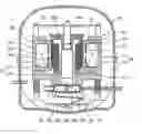
FIG. 1 is a cross-section showing an entire configuration of a linear compressor, according to the present invention; and
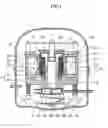
FIG. 2 is a partially cutaway perspective view showing a combination of an inner stator with a cylinder in the linear compressor of FIG. 1.
DETAILED DESCRIPTION OF THE PREFERRED EMBODIMENTSReference will now be made in detail to the present preferred embodiments of the present invention, examples of which are illustrated in the accompanying drawings, wherein like reference numerals refer to like elements throughout.
FIG. 1 is a cross-section of an entire construction of a linear compressor, according to the present invention.
Referring to FIG. 1, the linear compressor of the present invention includes a closed container 10 configured to form a closed structure by combining an upper container 11 with a lower container 12, a compression unit 20 provided in the closed container 10 to compress a refrigerant, and a drive unit 30 adapted to provide power to the compression unit 20.
The compression unit 20 includes a cylinder block 21 into which a cylinder 22 defining a compression chamber 22a and a support part 23 extending outward from a circumference of a lower part of the cylinder 22 are integrated, and a piston 24 which is placed in the compression chamber 22a to be reciprocated. A cylinder header 25 is placed under the cylinder 22 to draw or discharge the refrigerant.
An intake chamber 25a and a discharge chamber 25b are formed in the cylinder head 25, and operate in conjunction with the compression chamber 22a to draw and discharge the refrigerant when the piston 25 reciprocates. Furthermore, a valve plate 26, on which an intake valve 26a and a discharge valve 26b are mounted to selectively open and close the intake chamber 25a and the discharge chamber 25b, respectively, is provided between the cylinder head 25 and the cylinder 22.
The drive unit 30 includes a linear motor including an inner stator 31 placed outside of the cylinder 22, an outer stator 32 spaced apart from the inner stator 31 by a predetermined interval, and a mover 33 provided between the inner and outer stators 31 and 32 to interact with a magnetic field passing through an space between the inner and outer stators 31 and 32.
The mover 33 includes a magnet 33a constructed to form a cylindrical shape and fixed to encircle an outside of the cylinder 22, and a fastening part 33b to fixedly support the magnet 33a. The fastening part 33b of the mover 33 is coaxially combined with a connection shaft 24a provided at an upper end of the piston 24 so that the fastening part 33b of the mover 33 reciprocates together with the piston 24.
The outer stator 32 is constructed so that coils 32b to generate a magnetic flux is wound through an outer core 32a to form a passage of the magnetic flux. Additionally, a lower end of the outer stator 32 is supported by the support part 23 of the cylinder block 21, and an upper end of the outer stator 32 is supported by a fastening frame 40.
The inner stator 31 includes an inner core 31a that functions as a passage of the magnetic flux, like the outer core 32a. The magnetic flux generated from the outer stator 32 flows to the inner core 31a of the inner stator 31 through the magnet 33a of the mover 33.
A combination of the inner stator 31 with the cylinder 22 in the linear compressor of the present invention is described with reference to FIG. 2 below.
Referring to FIG. 2, the inner stator 31 further includes a holder 31b to be combined with an outside of the cylinder 22, and the inner core 31a is fastened to an outside of the holder 31b.
The holder 32b has a cylindrical shape corresponding to that of the cylinder 22. A first threaded part 31c is formed on an inner surface of the holder 31b to allow the inner stator 31 to be combined with the cylinder 22, and a second threaded part 22b is formed on an outer surface of the cylinder 22 to engage with the first threaded part 31c.
The inner stator 31 is securely fastened to the cylinder 22 by allowing the threaded parts 31c and 22b to be engaged with each other in an interlocking fashion.
As described above, the linear compressor according to the present invention allow the holder to be combined with the cylinder in an interlocking fashion by forming the first threaded part on the inner surface of the holder, the outer side of which on the inner core is mounted, and the second threaded part on the outer surface of the cylinder to correspond to the first threaded part.
Accordingly, it is possible to securely fasten the holder to the cylinder without screws, thus reducing a number of manufacturing steps, and manufacturing costs.
Furthermore, the linear compressor according to the present invention prevents the cylinder from being deformed when the holder is combined with the cylinder, thus improving reliability thereof.
Although a few preferred embodiments of the present invention have been shown and described, it would be appreciated by those skilled in the art that changes may be made in these embodiments without departing from the principles and spirit of the invention, the scope of which is defined in the claims and their equivalents.
Claims
1. A linear compressor, comprising:
outer and inner stators to form a magnetic field;
a mover to move a piston while reciprocating between the outer and inner stators;
a cylinder in which a refrigerant is compressed by the moving of the piston;
a first threaded part formed on an inner surface of the inner stator; and
a second threaded part formed on an outer surface of the cylinder to engage with the first threaded part.
2. The linear compressor as set forth in claim 1, wherein:
the inner stator comprises an inner core to form a magnetic flux, and a holder to fasten the inner core; and
the first threaded part is formed on an inner surface of the holder.
Images & Drawings included:

Sources:
- United States Patent and Trademark Office - verify current appl. status at the USPTO↗
Similar patent applications:
- » 20060171814
Linear-compressor control system, a method of controlling a linear compressor, a linear compressor and cooling system - » 20170152847
Actuation system for a resonant linear compressor, method for actuating a resonant linear compressor, and resonant linear compressor - » 20140186194
Actuation system for a resonant linear compressor, method for actuating a resonant linear compressor, and resonant linear compressor - » 20150377228
Linear compressor, shell for linear compressor, and method for manufacturing shell of linear compressor - » 20080314056
Linear-compressor control system, a method of controlling a linear compressor and a linear compressor - » 20130189119
System for controlling a resonant linear compressor piston, method for controlling a resonant linear compressor piston, and resonant linear compressor - » 20170030345
System for controlling a resonant linear compressor piston, method for controlling a resonant linear compressor piston, and resonant linear compressor - » 20120141300
Linear motor, a linear compressor, a method of controlling a linear compressor, a cooling system, and a linear compressor controlling a system - » 20150071792
Linear motor, a linear compressor, a method of controlling a linear compressor, a cooling system, and a linear compressor controlling a system - » 20070159128
Linear motor, a linear compressor, a method of controlling a linear compressor, a cooling system, and a linear compressor controlling a system
Recent applications in this class:
- » 20230213025 2023-07-06
Linear compressor and planar spring assembly - » 20230151802 2023-05-18
SYSTEMS AND METHODS FOR COMPRESSION AND EXPANSION OF GAS - » 20230074710 2023-03-09
Mechanical Resonant Pump - » 20230017414 2023-01-19
Compressor unit of a split stirling cryogenic refrigeration device - » 20220389920 2022-12-08
High Volume, Low Pressure Oilless Pump - » 20220389919 2022-12-08
Compressor - » 20220389918 2022-12-08
Compressor - » 20220154708 2022-05-19
Linear compressor - » 20220090590 2022-03-24
Linear compressor - » 20220065238 2022-03-03
Linear compressor