Integrated fuel cell power system
US20050112438A1
2005-05-26
10/973,044
2004-10-25
✅ Patent granted
US 7,183,016 B2
2007-02-27
-
-
Bruce F. Bell
2024-10-25
Abstract:
The present invention is a fuel cell power system, with a fuel cell stack, a multi-function mounting plate, at least two fuel supply units, a distribution manifold, a gas pressure regulator, and a cover. The distribution manifold and gas pressure regulator may be integrated into the mounting plate. The mounting plate also serves as an end plate for the fuel cell stack. The system allows for continuous, uninterrupted use, since at least one fuel supply unit is removable, and the system can operate from another supply unit while the removable unit is being replaced.
Assignee:
- ALTERGY SYSTEMS 12 🇺🇸 Folsom, CA, United States
Interested in similar patents?
Get notified when new applications in this technology area are published.
Classification:
H01M8/04 IPC
Fuel cells; Manufacture thereof Auxiliary arrangements, e.g. for control of pressure or for circulation of fluids
H01M8/04089 » CPC main
Fuel cells; Manufacture thereof; Auxiliary arrangements, e.g. for control of pressure or for circulation of fluids; Arrangements for control of reactant parameters, e.g. pressure or concentration of gaseous reactants
H01M8/04201 » CPC further
Fuel cells; Manufacture thereof; Auxiliary arrangements, e.g. for control of pressure or for circulation of fluids; Arrangements for control of reactant parameters, e.g. pressure or concentration Reactant storage and supply, e.g. means for feeding, pipes
H01M8/04208 » CPC further
Fuel cells; Manufacture thereof; Auxiliary arrangements, e.g. for control of pressure or for circulation of fluids; Arrangements for control of reactant parameters, e.g. pressure or concentration; Reactant storage and supply, e.g. means for feeding, pipes Cartridges, cryogenic media or cryogenic reservoirs
H01M8/2475 » CPC further
Fuel cells; Manufacture thereof; Grouping of fuel cells, e.g. stacking of fuel cells; Details of groupings of fuel cells; Arrangements for tightening a stack, for accommodation of a stack in a tank or for assembling different tanks Enclosures, casings or containers of fuel cell stacks
H01M8/2484 » CPC further
Fuel cells; Manufacture thereof; Grouping of fuel cells, e.g. stacking of fuel cells; Details of groupings of fuel cells characterised by external manifolds
H01M8/2485 » CPC further
Fuel cells; Manufacture thereof; Grouping of fuel cells, e.g. stacking of fuel cells; Details of groupings of fuel cells characterised by external manifolds Arrangements for sealing external manifolds; Arrangements for mounting external manifolds around a stack
H01M2008/1095 » CPC further
Fuel cells; Manufacture thereof; Fuel cells with solid electrolytes Fuel cells with polymeric electrolytes
Y02E60/50 » CPC further
Enabling technologies; Technologies with a potential or indirect contribution to GHG emissions mitigation; Hydrogen technology Fuel cells
Y02E60/50 » CPC further
Enabling technologies; Technologies with a potential or indirect contribution to GHG emissions mitigation; Hydrogen technology Fuel cells
Description
RELATED PATENTSThe present application is a continuation of U.S. application Ser. No. 10/126,165, filed on Apr. 18, 2002.
FIELD OF THE INVENTIONThe present invention relates to fuel cell power systems.
BACKGROUNDFuel cell power systems include a number of components, including the fuel cell stack, the fuel supply, a pressure regulator to control the flow of the fuel supply, and various tubes and fittings that serve as manifolds for distribution of fuel through the system. Fuel cells typically use hydrogen gas as a fuel but other fuels such as methyl alcohol (methanol) or reformed hydrocarbons (reformate) may be used.
SUMMARY OF THE INVENTIONThe present invention is an integrated fuel cell system, comprised of a fuel cell stack or stacks, an integrated, multi-function mounting plate, fuel supply unit(s), a distribution manifold, a gas pressure regulator, and a cover. By integrating components, the present invention helps improve fuel cell operation, and lowers component count and assembly costs.
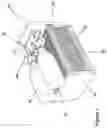
BRIEF DESCRIPTION OF THE DRAWINGSFIG. 1 is a perspective view of a fuel cell system according to the present invention, without a cover.
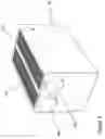
FIG. 2 is a perspective view of a fuel cell system according to the present invention, with a cover.
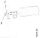
FIG. 3a is a perspective view of a fuel supply unit with a bayonet mount.
FIG. 3b is a perspective view of another fuel supply unit with a spring-loaded mount.
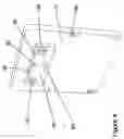
FIG. 4 is a perspective view of a mounting plate according to the present invention, showing the internal gas distribution plumbing.
DETAILED DESCRIPTIONThe present invention is an integrated fuel cell power system 10, comprised of a fuel cell stack 20, an integrated, multi-function mounting plate 30, fuel supply unit(s) 40, 42, a distribution manifold 50, a gas pressure regulator 60, and a cover 70.
As shown in FIG. 1, the fuel cell stack 20 is comprised of an array of individual fuel cells 22, and an end plate 24. The mounting plate 30 functions as a fuel cell end plate. The integrated system of the present invention can work with virtually any polymer electrolyte membrane (PEM) fuel cell stack, including but not limited to stacks comprised of integrated fuel cells, or more conventional stacks comprised of fuel cells assembled from separate stand-alone components. The present invention can work with systems that use ambient or pressurized air as an oxidizer, either in natural convection mode or forced air mode.
As shown in FIGS. 1 & 4, the mounting plate 30 serves two functions. First, the plate serves as an end plate for the fuel cell stack.
Second, integrated within or attached to the mounting plate is a fuel distribution manifold 50, and a gas pressure regulator 60. The manifold receives fuel from the fuel supply units 40, 42. From the manifold, the fuel passes through the regulator 60 and into the stack 20. The distribution manifold contains valves 52, 54 for receiving fuel from the fuel supply units 40, 42. These valves engage complementary valve 44 attached to the fuel supply unit(s). Both manifold valves 52, 54 and the fuel supply unit valve 44 are self-sealing, so that when the fuel supply units are removed from the manifold the valves close, ensuring that no gas will escape.
The manifold 50 distributes high pressure gas to the pressure regulator 60, FIG. 1, through internal passages 56, 58 and regulator inlet port 62 shown in FIG. 4.
The pressure regulator 60 reduces the pressure of the fuel gas so that it is suitable for use by the fuel cell stack. Regulators of a suitable type can be supplied commercially from different vendors, for example: Air-Logic, 5102 Douglass Avenue, Racine, Wis. The regulated fuel is then conveyed out of the pressure regulator to the fuel cell stack 20 by passing from the pressure regulator through the regulated gas pressure port 64 of the distribution manifold 50 and then through internal passage 57 and into the fuel cell stack by way of the fuel cell inlet port 66. The regulated gas can also be transmitted to the stack 20 from the regulator 60 through external piping hoses or tubes. The output pressure of the regulator is adjusted or set by means of a set screw, knob, dial, or other output control means. The pressure regulator can but need not be integrated with the mounting plate.
The mounting plate can be expanded to accommodate more than one set of manifolds and pressure regulators, so that more than one set of fuel cell stacks can be used with a single plate.
The fuel supply units can take many forms. As shown in FIGS. 1, 3a, and 3b, they can be in the form of conventional pressurized gas storage bottles or methanol tanks. Additionally, metal hydride fuel cartridges can be used, such as the “Hydrogen Storage System, Model Number ST-1-AL” supplied by ERGENICS, INC., 247 Margaret King Ave., Ringwood, N.J. Fuel can also be supplied from an external source such as large pressurized hydrogen gas bottles or other standard methods of supplying hydrogen such as reformers. The units can connect to the distribution manifold through a bayonet-type connection 46, as shown in FIG. 3, or through other conventional methods known to those skilled in the mechanical arts, including but not limited to a screw thread, or spring-loaded attachments 48. (FIG. 3b).
The system of the present invention can be operated continuously, meaning that replacement fuel sources can be removed and reinstalled while the system is operating, resulting in uninterrupted use. In one embodiment of the present invention, both fuel supply units are removable fuel units, and a single spent fuel unit can be removed and replaced while the system operates off the other one. In an alternative embodiment, one fuel supply unit or cartridge is permanent and the other is removable. The system can run off the permanent supply while the removable supply is replaced with a fresh cartridge or other supply unit. The permanent supply can then be refilled from fuel in the removable unit. The permanent supply can take the form of a pressurized gas bottle, a hydride cartridge, bladder, or other suitable container. Even those with little or no technical experience should have little trouble replacing cartridges or other supply units within the present invention.
The fuel supply units are recharged or refilled using standard methods used in the industry. The valve 44 opens automatically when connected to a charging or filling unit and when charged or refilled and removed from the charging or filling unit they then self seal and are ready for immediate use.
As shown in FIG. 2, the cover 70 encloses the fuel cell system, but allows for easy access to the fuel supply units 40, 42. The fuel supply units 40, 42 can be removed without removing the cover 70. The cover has slots 72 or louvers to facilitate proper air circulation.
One skilled in the art will appreciate that the present invention can be practiced by other than the described embodiments, which are presented for purposes of illustration and not limitation. Various modifications and changes can be made to the fuel supply units, valves, pressure regulators, mounting plate and the like without departing to the scope of the present invention.
Claims
1. An integrated fuel cell power system, comprising:
a. a stack of fuel cells;
b. a mounting plate serving as an end plate for said fuel cells, said mounting plate comprising:
i. a plate; and
ii. a fuel distribution manifold for receiving fuel and distributing fuel, said manifold associated with said plate;
c. a gas pressure regulator connected to said fuel distribution manifold; and
d. a fuel supply unit associated with said plate.
2. The integrated fuel cell power system according to claim 1, wherein said manifold is integrated with said plate.
3. The integrated fuel cell power system according to claim 1, wherein said manifold is attached to said plate.
4. The integrated fuel cell power system according to claim 1, wherein said fuel supply unit is integrated with said plate.
5. The integrated fuel cell power system according to claim 1, wherein said fuel supply unit is external said plate.
6. The integrated fuel cell power system according to claim 1, wherein said manifold is integrated with said plate and said fuel supply unit is integrated with said plate.
7. The integrated fuel cell power system according to claim 1, wherein said manifold is integrated with said plate and said fuel supply unit is external said plate.
8. The integrated fuel cell power system according to claim 1, wherein said manifold is attached to said plate and said fuel supply unit is integrated with said plate.
9. The integrated fuel cell power system according to claim 1, wherein said manifold is attached to said plate and said fuel supply unit is external said plate.
10. The fuel cell power system according to claim 1, additionally comprising a second fuel supply unit.
11. The fuel cell power system according to claim 2, additionally comprising a second fuel supply unit.
12. The fuel cell power system according to claim 3, additionally comprising a second fuel supply unit.
13. The fuel cell power system according to claim 4, additionally comprising a second fuel supply unit.
14. The fuel cell power system according to claim 5, additionally comprising a second fuel supply unit.
15. The fuel cell power system according to claim 6, additionally comprising a second fuel supply unit.
16. The fuel cell power system according to claim 7, additionally comprising a second fuel supply unit.
17. The fuel cell power system according to claim 8, additionally comprising a second fuel supply unit.
18. The fuel cell power system according to claim 9, additionally comprising a second fuel supply unit.
Images & Drawings included:

Sources:
- United States Patent and Trademark Office - verify current appl. status at the USPTO↗
Similar patent applications:
- » 10351790
Thermally integrated fuel cell power system - » 20050175870
Cogeneration of power and heat by an integrated fuel cell power system - » 20070190371
INTEGRATED FUEL CELL POWER SYSTEM - » 10141493
Cogeneration of power and heat by an integrated fuel cell power system - » 20150147667
Gasifier having integrated fuel cell power generation system - » 20120094198
Gasifier having integrated fuel cell power generation system - » 20080246432
FUEL CELL POWER SUPPLY SYSTEM INTEGRATED WITH RECHARGEABLE BATTERIES - » 20100013317
Integrated fuel cell system with auxiliary power delivery - » 20130009481
Integrated fuel cell system with auxiliary power delivery - » 20100028730
Fuel cell power production system with an integrated hydrogen utilization device
Recent applications in this class:
- » 20250279445 2025-09-04
FUEL EJECTOR FOR A FUEL CELL - » 20250260027 2025-08-14
CROSS-CELL LEAK DETECTION AND SAMPLE CONDITIONING SYSTEM - » 20250246648 2025-07-31
FUEL CELL - » 20250192197 2025-06-12
VALVE AND A FUEL CELL SYSTEM INCORPORATING THE VALVE - » 20250038228 2025-01-30
MIXED MEDIA DESULFURIZATION SYSTEMS AND FUEL CELL SYSTEMS INCLUDING THE SAME - » 20240421330 2024-12-19
THROTTLE FLAP ACTUATOR UNIT, FUEL CELL SYSTEM HAVING A THROTTLE FLAP ACTUATOR UNIT OF SAID TYPE, AND MOTOR VEHICLE HAVING A FUEL CELL SYSTEM OF SAID TYPE - » 20240372119 2024-11-07
FUEL CELL SYSTEMS AND METHODS OF SIZING AND OPERATING AN EJECTOR BY USING A BY-PASS VALVE - » 20240347744 2024-10-17
FUEL CELL SYSTEM FOR PERFORMANCE RECOVERY AND OPERATION METHOD THEREOF - » 20240313236 2024-09-19
INJECTION MODULE FOR A CONVEYOR ASSEMBLY OF A FUEL CELL SYSTEM - » 20240290999 2024-08-29
COMPRESSOR ASSEMBLY FOR A FUEL CELL SYSTEM, IN PARTICULAR FOR A FUEL CELL SYSTEM FOR COMMERCIAL VEHICLES
Recent applications for this Assignee:
- » 20180115010 2018-04-26
Collapsing fuel cell isolator for fuel cell airflow management - » 20170288239 2017-10-05
VENTED POWER SYSTEM RETROFIT - » 20170214073 2017-07-27
MODULAR UNIT FUEL CELL ASSEMBLY - » 20170012304 2017-01-12
INTEGRATED RECIRCULATING FUEL CELL SYSTEM - » 20150311548 2015-10-29
Integrated recirculating open cathode fuel cell system - » 20150295257 2015-10-15
Integrated recirculating fuel cell methods - » 20120214077 2012-08-23
Integrated recirculating fuel cell system - » 20110162784 2011-07-07
MEMBRANE ELECTRODE ASSEMBLY FABRICATION - » 20090169939 2009-07-02
Modular unit fuel cell assembly - » 20080070081 2008-03-20
Integrated and modular BSP/MEA/manifold plates for fuel cells