DEVICE AND METHOD USING FLEXIBLE CIRCUIT SECURED FOR RELIABLY INTER-CONNECTING COMPONENTS THEREIN IN THE PRESENCE OF VIBRATION EVENTS
US20050112913A1
2005-05-26
10/994,826
2004-11-22
Abstract:
Device and method including a generally flat and flexible circuit for electrically inter-connecting components therein are provided. The device includes a post including a recessed section configured to receive the flexible circuit through an opening in said circuit. The structures defining the opening in the flexible circuit may be configured to provide a snap-fit between the circuit and the recessed section of the post, and thus avoid undesirable movement of the flex circuit in the presence of vibration.
Interested in similar patents?
Get notified when new applications in this technology area are published.
Classification:
H01F5/04 » CPC main
Coils Arrangements of electric connections to coils, e.g. leads
H01R12/59 » CPC further
Structural associations of a plurality of mutually-insulated electrical connecting elements, specially adapted for printed circuits, e.g. printed circuit boards [PCBs], flat or ribbon cables, or like generally planar structures, e.g. terminal strips, terminal blocks; Coupling devices specially adapted for printed circuits, flat or ribbon cables, or like generally planar structures; Terminals specially adapted for contact with, or insertion into, printed circuits, flat or ribbon cables, or like generally planar structures; Fixed connections for flexible printed circuits, flat or ribbon cables or like structures
H05K3/306 » CPC further
Apparatus or processes for manufacturing printed circuits; Assembling printed circuits with electric components, e.g. with resistor Lead-in-hole components, e.g. affixing or retention before soldering, spacing means
H05K3/306 » CPC further
Apparatus or processes for manufacturing printed circuits; Assembling printed circuits with electric components, e.g. with resistor Lead-in-hole components, e.g. affixing or retention before soldering, spacing means
H05K1/189 » CPC further
Printed circuits; Printed circuits structurally associated with non-printed electric components characterised by the use of a flexible or folded printed circuit
H05K1/189 » CPC further
Printed circuits; Printed circuits structurally associated with non-printed electric components characterised by the use of a flexible or folded printed circuit
H05K2201/091 » CPC further
Indexing scheme relating to printed circuits covered by; Shape and layout; Substrate related Locally and permanently deformed areas including dielectric material
H05K2201/091 » CPC further
Indexing scheme relating to printed circuits covered by; Shape and layout; Substrate related Locally and permanently deformed areas including dielectric material
H05K2201/10568 » CPC further
Indexing scheme relating to printed circuits covered by; Details of components or other objects attached to or integrated in a printed circuit board; Details of mounted components Integral adaptations of a component or an auxiliary PCB for mounting, e.g. integral spacer element
H05K2201/1059 » CPC further
Indexing scheme relating to printed circuits covered by; Details of components or other objects attached to or integrated in a printed circuit board; Details of mounted components Connections made by press-fit insertion
H05K2201/1059 » CPC further
Indexing scheme relating to printed circuits covered by; Details of components or other objects attached to or integrated in a printed circuit board; Details of mounted components Connections made by press-fit insertion
H05K2201/10598 » CPC further
Indexing scheme relating to printed circuits covered by; Details of components or other objects attached to or integrated in a printed circuit board; Details of mounted components Means for fastening a component, a casing or a heat sink whereby a pressure is exerted on the component towards the PCB
H05K2203/167 » CPC further
Indexing scheme relating to apparatus or processes for manufacturing printed circuits covered by; Inspection; Monitoring; Aligning Using mechanical means for positioning, alignment or registration, e.g. using rod-in-hole alignment
H05K2203/167 » CPC further
Indexing scheme relating to apparatus or processes for manufacturing printed circuits covered by; Inspection; Monitoring; Aligning Using mechanical means for positioning, alignment or registration, e.g. using rod-in-hole alignment
Description
BACKGROUND OF THE INVENTIONThe present invention is generally related to electrical or electromechanical devices, and, more particularly, to apparatus and techniques for securely affixing and routing in such devices, notwithstanding the presence of vibration, conductor circuit elements, such as may be made up of generally thin, flat, and flexible elements, commonly referred to as a “flex circuit”.
Electrical or electromechanical devices, e.g., modular devices, used in equipment subject to vibration, such as may be used in automotive, aerospace, and other industrial applications need to be carefully designed to be substantially unaffected when exposed to any such vibration. For example, these devices may use flexible conductors to make electrical connections between one or more components associated with the device, such as electronic, sensor and actuator components. During vibration conditions, the flexible circuit has a tendency to randomly move around, and rub on the components internal to the module. This rubbing action could eventually cause wear and tear of the flexible circuit, which can result in undesirable electrical shorts.
Unfortunately, prior to the present invention, some possible techniques for somewhat alleviating the vulnerability of the flexible circuit to vibration-induced rubbing and eventual wear-out tend to introduce new problems. For example, one could glue the flexible circuit to a can or housing that encloses the device in order to prevent movement of the flexible circuit. Another possible solution would be to add an additional protective layer of plastic to the flexible circuit. This second layer would serve as a barrier, which would have to be worn through before the flexible circuit would become exposed. However, neither of these solutions is fully satisfactory. The use of glue is generally a messy and time-consuming process; and providing the additional protective layer is not a fool-proof solution, since the protective layer still would be subject to the rubbing action and that layer could eventually be worn through.
Thus, it is desirable to provide affixing technique and structure that, at a low-cost, reliably avoids the foregoing issues. It would be further desirable to provide affixing technique and structure that would result in a more reliable and durable electrical connection in the modular device, notwithstanding of exposure to vibration.
BRIEF SUMMARY OF THE INVENTIONGenerally, the present invention fulfills the foregoing needs by providing in one aspect thereof a device including a generally flat and flexible circuit for electrically inter-connecting components therein. The device includes a post including a recessed section configured to receive the flexible circuit through an opening in said circuit. The structures defining the opening in the flexible circuit may be configured to provide a snap-fit between the circuit and the recessed section of the post, and thus avoid undesirable movement of the flex circuit in the presence of vibration.
The present invention further fulfils the foregoing needs by providing in another aspect thereof a method for inter-connecting components in a device using a generally flat and flexible circuit. The method allows providing a post including a recessed section configured to receive the flexible circuit through an opening in the circuit. The method further allows configuring the structures defining the opening in the flexible circuit to provide a snap-fit between the circuit and the recessed section of the post, and thus avoid undesirable movement of the flex circuit in the presence of vibration.
In yet another aspect thereof, the present invention provides a method for assembling a generally flat and flexible circuit providing interconnections in a device. The method allows providing a post including recessed and non-recessed sections. The recessed section is configured to receive the flexible circuit through an opening in a first segment of the circuit. The method further allows inserting the non-recessed portion of the post through the opening in the flexible circuit. Insertion is continued until the first segment of the flexible circuit is received by the recessed section to provide a snap-fit therebetween.
BRIEF DESCRIPTION OF THE DRAWINGSThe features and advantages of the present invention will become apparent from the following detailed description of the invention when read with the accompanying drawings in which:
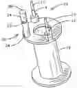
FIG. 1 illustrates an isometric view of an exemplary device embodying aspects of the invention, such as a post that may be used to separate a flex circuit from any components and structures inside of the device.
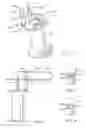
FIG. 2 is a plan view of the device of FIG. 1.
FIGS. 3 and 4 respectively illustrate exemplary embodiments of an opening situated in the flex circuit and configured to slidably allow inserting the flex circuit through post to reach a recess on the post.
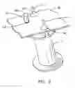
FIG. 5 is an isometric view illustrating exemplary connections, e.g., soldering connections, between the flex circuit and respective terminals of the device of FIG. 1.
DETAILED DESCRIPTION OF THE INVENTIONFIG. 1 illustrates an isometric view of an exemplary device 10 embodying aspects of the invention. In one exemplary embodiment, device 10 comprises a spool 12 that may be used for carrying a winding, and other associated components (not shown). Spool 12 may be constructed of plastic or any suitable polymer that may be molded into any desired configuration using molding techniques well understood by those skilled in the art, such as injection molding. Device 10 may be part of a piece of equipment that may be used in automotive, aerospace, and other industrial applications to provide electrical signals useful to achieve any desired equipment functionality. In one exemplary embodiment, spool 12 may include terminals 17 that in turn may include affixing pads 14 and 16, e.g., soldering pads or equivalent, connectable to a generally thin, flat, and flexible (flex) circuit 18, (FIG. 2).
The inventor of the present invention has innovatively recognized that a post 20 may be used to separate flex circuit 18 from any components and structures inside of the device, which otherwise could harm the flex circuit during a vibration condition. In one exemplary embodiment, post 20 is formed as an integral structure of spool 12 and comprises a generally cylindrical post. It will be understood, however, that the present invention does not require the post to be cylindrical, since other configurations may be used for the post, such as polygonal, triangular, square, oval, etc. As shown in FIG. 1, post 20 includes a recessed section 22 with a smaller diameter relative to non-recessed sections 24. In one exemplary embodiment, recess 22 is disposed generally intermediate relative to the opposite ends of the post to allow a first segment 26 of the flex circuit to be securely held in place. In one embodiment, the positioning of recess 22 along post 20 relative to the soldering or affixing pads on terminals 14 and 16 may be chosen to share a common alignment between one another, such as sharing a common horizontal plane, to facilitate the soldering or affixing operation for connecting the flex circuit to terminals 17. As further shown in FIG. 2, in one exemplary embodiment, the flex circuit may be foldable over itself to form a second segment 28. This second segment may be supportable by the top end of post 20, where it would be isolated from any other components inside the enclosure.
FIGS. 3 and 4 respectively illustrate respective embodiments of an opening 30 situated in the flex circuit and configured to slidably allow inserting the flex circuit through post 20. As used herein the term opening encompasses any opening that may result within opposing resilient structures, such as may be formed in a flexible material like the material of which the flex circuit is made up, either in the form of closely juxtaposed slits 32, or in the form of spaced-apart gripping facets 34. Once the flex circuit is pushed along the post to reach the recess section, the slits or gripping facets, due to their springiness characteristics would expand into the recess and allow for providing a snap-fit between the first segment of the flex circuit and the post. The opening in FIG. 3 comprises closely juxtaposed slits, and may be analogized to the opening in a lid of a drinking cup that allows passage to a straw into the cup. Conversely, the opening in FIG. 4 comprises spaced-apart gripping facets in an exemplary star-shaped opening. It will be appreciated by those skilled in the art that the present invention is not limited to any specific configuration for the opening in the flex circuit so long as that configuration is able to allow sliding the flex circuit through the non-recessed sections of the post, and then allow providing a snap-fit when the flex circuit is at the recess. In operation, the opposing structures or gripping facets that define the opening in the flex circuit cooperate with the recessed section of the post to provide a secure mechanical connection that allows reducing or eliminating the possibility of the flex circuit rubbing with any internal components of the device in the event of vibration conditions. As will be appreciated by those skilled in the art, snap-fit generally refers to any mechanical means of fastening two or more objects together by which structural features of one object interlock with corresponding features of another object thus achieving a secure connection between the two objects.
FIG. 5 is an isometric view illustrating exemplary connections, e.g., soldering connections 40, between the flex circuit 18 and respective terminals 17 of the device. In one exemplary embodiment, the connection may be made through affixing pads 14 and 16 (FIG. 1) that may be part of the terminals. It will be appreciated that soldering is just one example of one technique for connecting the terminals to the flex circuit. Those skilled in the art will readily recognize many other standard affixing techniques that could be used in lieu of soldering, such as solderless affixing techniques.
While the preferred embodiments of the present invention have been shown and described herein, it will be obvious that such embodiments are provided by way of example only. Numerous variations, changes and substitutions will occur to those of skill in the art without departing from the invention herein. Accordingly, it is intended that the invention be limited only by the spirit and scope of the appended claims.
Claims
1. A device including a generally flat and flexible circuit for electrically inter-connecting components therein, the device comprising:
a spool;
a generally cylindrical post that is integral with said spool, including a recessed section configured to receive the flexible circuit through an opening in said circuit, the structures defining the opening in the flexible circuit being configured to provide a snap-fit between the circuit and the recessed section of the post, and thus avoid undesirable movement of the flex circuit in the presence of vibration.
2. The device of claim 1 further comprising one or more terminals extending from the spool, each terminal including an affixing pad, and wherein the recess is positioned relative to the affixing pads to share a common alignment therebetween.
3. The device of claim 1 wherein the structures defining the opening are arranged to form a plurality of closely juxtaposed slits.
4. The device of claim 1 wherein the structures defining the opening comprise a plurality of gripping facets.
Images & Drawings included:
Sources:
- United States Patent and Trademark Office - verify current appl. status at the USPTO↗
Recent applications in this class:
- » 20250166877 2025-05-22
COIL COMPONENT - » 20250157709 2025-05-15
INDUCTOR AND POWER SUPPLY - » 20250149218 2025-05-08
INDUCTOR COMPONENT - » 20250149217 2025-05-08
COIL ELECTRONIC COMPONENT AND MANUFACTURING METHOD THEREOF - » 20250149216 2025-05-08
TERMINAL CONNECTOR - » 20250132077 2025-04-24
COIL COMPONENT - » 20250111970 2025-04-03
Inductive Component and Preparation Method Therefor - » 20250111969 2025-04-03
ELECTRONIC COMPONENT - » 20250069790 2025-02-27
COIL COMPONENT - » 20250029760 2025-01-23
COIL DEVICE