Intake manifold
US20050115535A1
2005-06-02
10/967,184
2004-10-19
✅ Patent granted
US 7,171,934 B2
2007-02-06
-
-
Stephen K. Cronin | Hyder Ali
2024-10-19
Abstract:
In a branch pipe of an intake manifold, portion c in the central part is kept at relatively small constant inner diameter for an interval C, and portion e of which an end is connected to the surge tank is kept at relatively large constant inner diameter for an interval E, whereby the volumetric efficiency at the time of medium speed and high speed of engine is excellent.
Inventors:
- Yoshinori Yakabe 1 🇯🇵 Aichi, Japan
- Atsuhito Ito 1 🇯🇵 Aichi, Japan
- Yoshinori Takabe 1 🇯🇵 Aichi, Japan
Assignee:
- MITSUBISHI JIDOSHA KOGYO KABUSHIKI KAISHA 756 🇯🇵 Tokyo, Japan
- MITSUBISHI JIDOSHA ENGINEERING KABUSHIKI KAISHA 54 🇯🇵 Okazaki-shi, Japan
- Mitsubishi Jidosha Engineering Kabushiki Kaisha 6 🇯🇵 Okazaki, Japan
Interested in similar patents?
Get notified when new applications in this technology area are published.
Classification:
F02M35/104 IPC
Combustion-air cleaners, air intakes, intake silencers, or induction systems specially adapted for, or arranged on, internal-combustion engines; Air intakes; Induction systems Intake manifolds
F02M35/112 » CPC main
Combustion-air cleaners, air intakes, intake silencers, or induction systems specially adapted for, or arranged on, internal-combustion engines; Air intakes; Induction systems; Intake manifolds for engines with cylinders all in one line
F02B27/006 » CPC further
Use of kinetic or wave energy of charge in induction systems, or of combustion residues in exhaust systems, for improving quantity of charge or for increasing removal of combustion residues; Oscillating pipes with charging achieved by arrangement, dimensions or shapes of intakes pipes or chambers; Ram air pipes of intake runners
F02M35/10072 » CPC further
Combustion-air cleaners, air intakes, intake silencers, or induction systems specially adapted for, or arranged on, internal-combustion engines; Air intakes; Induction systems characterised by the position of elements of the air intake system in direction of the air intake flow, i.e. between ambient air inlet and supply to the combustion chamber Intake runners
F02M35/10111 » CPC further
Combustion-air cleaners, air intakes, intake silencers, or induction systems specially adapted for, or arranged on, internal-combustion engines; Air intakes; Induction systems characterised by details of intake ducts: shapes; connections; arrangements Substantially V-, C- or U-shaped ducts in direction of the flow path
F02M35/10118 » CPC further
Combustion-air cleaners, air intakes, intake silencers, or induction systems specially adapted for, or arranged on, internal-combustion engines; Air intakes; Induction systems characterised by details of intake ducts: shapes; connections; arrangements with variable cross-sections of intake ducts along their length; Venturis; Diffusers
Y02T10/12 » CPC further
Road transport of goods or passengers; Internal combustion engine [ICE] based vehicles Improving ICE efficiencies
Y02T10/12 » CPC further
Road transport of goods or passengers; Internal combustion engine [ICE] based vehicles Improving ICE efficiencies
Description
CROSS-REFERENCE TO RELATED APPLICATIONThis application incorporates by references the subject matter of Application NO. 2003-359914 filed in Japan on 20 Oct. 2003, on which a priority claim is based under 35 U.S.C §119(a).
BACKGROUND OF THE INVENTION1. Field of the Invention
The present invention relates to an intake manifold for an engine, and more particularly to a structure of a branch pipe thereof.
2. Description of the Related Art
Conventionally, in an intake manifold for an engine, each branch pipe 3 connected to an intake port 2 of a cylinder head 1 has an opening 4 on the intake port 2 which has an inner diameter almost equal to that of the intake port 2. The inner diameter of the branch pipe 3 gradually increases toward the other opening 6 connected to a surge tank 5, as illustrated in FIG. 5. The intake air amount of cylinder in the engine or volumetric efficiency is affected by the length and inner diameter of the branch pipe 3.
That is, as the inner diameter of the branch pipe 3 in the intake manifold increases and the length of the branch pipe 3 decreases, the volumetric efficiency at the time of high speed of engine is increased to produce a higher output.
And as the inner diameter of the branch pipe 3 in the intake manifold decreases and the length of the branch pipe 3 increases, the volumetric efficiency at the time of medium speed or low speed of engine is increased to produce a higher output.
Accordingly, to increase the volumetric efficiency at the time of medium speed and low speed of engine, there is conventionally a case in which a mechanism for varying the length of the branch pipe according to the rotating speed of the engine is provided. But when the length of the branch pipe 3 is fixed as illustrated in FIG. 5, it is required to change the inner diameter of the branch pipe 3 according to the distance L from the opening 4 on the intake port in the branch pipe 3. Ideally, to obtain the excellent volumetric efficiency according to the engine characteristics, it is necessary to change the inner diameter of the branch pipe 3 according to the distance L from the opening 4 as shown in FIG. 6 in which the medium speed and high speed specifications are illustrated.
However, if the inner diameter of the branch pipe 3 in the engine is set in either the medium speed or high speed specifications for the engine, the volumetric efficiency at the time of high speed is greatly decreased for the branch pipe 3 in the medium speed specifications, or the volumetric efficiency at the time of medium speed is remarkably decreased for the branch pipe 3 in the high speed specifications, as represented by a curve x in the medium speed specifications or a curve y in the high speed specifications in FIG. 7.
In JP-A-10-213025, an intake manifold was disclosed in which a branch pipe has a constant inner diameter, and has a greater diameter near a connection portion with a surge tank. With this constitution, the intake air flow efficiency from the surge tank into the branch pipe is increased. However, with a technique as described in this publication, since the inner diameter of the branch pipe is constant from the intake port connection portion to the vicinity of the surge tank, the inner diameter of the branch pipe is almost equal to the diameter of the intake port. Accordingly, it is possible that the branch pipe of this shape has a greater branch pipe sectional area than the branch pipe having the same length, as illustrated in FIG. 5. Thereby it has the increased volumetric efficiency at the time of medium speed and the increased intake air flow efficiency. But there is a problem that the volumetric efficiency at the time of high speed is not improved.
SUMMARY OF THE INVENTIONIt is an object of the invention to provide a branch pipe of an intake manifold that has a relatively excellent volumetric efficiency at the time of medium speed and high speed of engine.
An intake manifold according to the invention comprises a branch pipe for connecting a cylinder head of an engine and a surge tank, wherein the branch pipe includes a first portion a passage sectional area of which is gradually increased from the cylinder head toward the surge tank, a second portion extending from the first portion and having a constant passage sectional area which is larger than that of the first portion, a third portion extending from the second portion and a passage sectional area of which is gradually increased, and a fourth portion extending from the third portion and having a constant passage sectional area which is larger than that of the third portion, an end portion of the fourth portion being connected to the surge tank.
That is, the passage sectional area of the fourth portion of the branch pipe on the side of the surge tank, apart from the cylinder head of the engine, is kept at a relatively large constant value between the cylinder head and the surge tank, whereby the volumetric efficiency at the time of high speed of engine is easily increased. And the passage sectional area of the second portion of the branch pipe near the cylinder head of the engine is kept at a relatively small constant value between the cylinder head and the surge tank, whereby the volumetric efficiency at the time of medium speed of engine is prevented from being deteriorated, so that the volumetric efficiency at the time of medium speed and high speed of the engine is kept at relatively high value as a whole.
BRIEF DESCRIPTION OF DRAWINGSThe nature of this invention, as well as other objects and advantages thereof, will be explained in the following with reference to the accompanying drawings, in which like reference characters designate the same or similar parts throughout the figures and wherein:
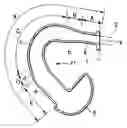
FIG. 1 is a schematic perspective view of an intake manifold according to an embodiment of the invention;
FIG. 2 is a cross-sectional enlarged view of an essential part of the intake manifold along the axial line;
FIG. 3 is a conceptual inner diameter variation chart of the essential part;
FIG. 4 is a chart for explaining the action of the intake manifold according to the embodiment;
FIG. 5 is a cross-sectional view of an essential part of the conventional device along the axial line;
FIG. 6 is a chart for explaining the structure of an intake pipe;
FIG. 7 is a chart for explaining the action of the conventional device; and
FIGS. 8A to 8F are explanatory views for explaining the action of a variation in the volumetric efficiency to the length of each portion/total length of the branch pipe at a predetermined rotating speed of the engine, and a variation in the volumetric efficiency to the inner diameter of the constant inner diameter of branch pipe/the length of the constant inner diameter of branch pipe.
DETAILED DESCRIPTION OF PREFERRED EMBODIMENTSIn the following embodiments, like reference characters designate the same or similar parts throughout the figures.
In FIGS. 1 to 3, an intake manifold 10 of a 4-cylinder engine has four branch pipes 11 corresponding to each cylinder, in which each branch pipe 11 connects an intake port 2 of a cylinder head 1 and a surge tank 5.
The branch pipe 11 has an opening 4 on the intake port 2 with an inner diameter almost equal to that of the intake port 2. Successively from the cylinder head 1 to the surge tank 5, the branch pipe 11 includes: portion “a” of the interval length A in which the inner diameter is kept equal to the inner diameter of the intake port 2, or the interval length A in which the inner diameter is slightly larger than the inner diameter of the intake port 2; portion “b” of the interval length B extending from portion “a”, in which the inner diameter is gradually increased; portion “c” of the interval length C extending from portion “b”, in which the inner diameter (diameter) is kept at a fixed value D1 that is larger than that of portion “a”; portion d of the interval length D extending from portion “c”, in which the inner diameter is gradually increased; and portion “e” of the interval length E extending from the portion d, in which the inner diameter (diameter) is kept at a fixed value D2 that is larger than that of portion “c” and an end portion of portion “e” is directly connected to the surge tank 5.
In the above explanation, the inner diameter of the branch pipe 11 is replaced with that of a perfect circle, which has the same cross-sectional area as a passage within the branch pipe 11. The cross-section of the branch pipe 11 may actually be a perfect circle.
A method for setting the inner diameters D1 and D2 of portion “c” and portion “e” of the branch pipe and the interval lengths C and E will be described.
First of all, a length X′ (X′=A′+B′+C′+D′+E′) of the branch pipe, at which the required characteristic (volumetric efficiency) of the engine is obtained especially at the time of high speed, is temporarily fixed.
Herein, X′ is an initial value of the length X of branch pipe before tuning, A′ is an initial value of interval length A before tuning, B′ is an initial value of interval length B before tuning, C′ is an initial value of interval length C before tuning, D′ is an initial value of interval length D before tuning, and E′ is an initial value of interval length E before tuning.
Further, the diameters D1′ and D2′ of the intervals with the constant inner diameter, in which the required characteristic (volumetric efficiency) of the engine is obtained, is temporarily fixed.
Herein, D1′ is an initial value of the inner diameter of portion “c” of the interval length C, and D2′ is an initial value of the inner diameter of portion “e” of the interval length E.
Herein, D1′ at which the required characteristic (volumetric efficiency) of the engine at the time of high speed is obtained is temporarily fixed, and D2′ at which the required characteristic (volumetric efficiency) of the engine at the time of medium speed is obtained is temporarily fixed.
In setting these temporarily fixed initial values, it should be noted that the length and diameter of the branch pipe are temporarily fixed in the light of mounting the engine on the vehicle.
Since X′ and D2′ have influence on the volumetric efficiency at the time of high speed, when the engine required characteristic is the maximum output or maximum torque at the time of high speed, X′ is equalized to X and D2′ is equalized to D2 to assure the volumetric efficiency at which the maximum output or maximum torque at the time of high speed is obtained, and then the tuning is performed to increase the volumetric efficiency at the time of medium speed.
That is, since X and D2 are already set in this case, the proportion of A, B, C, D and E and D1 are specifically set.
An actual machine test or simulation test is performed for the suction branch pipe in which the length X and area D2 of the branch pipe are fixed in this way, and the length and diameter D1 of each portion of the branch pipe are fixed, based on its test results.
For example, when the volumetric efficiency at the time of medium speed is too low to satisfy the engine requirement performance, the interval length C′ maybe increased and changed to C″, or the inner diameter of portion “c” may be changed to be small (D1″).
In this case, if the interval length of portion “cc” is simply increased, the length X′ of branch pipe becomes longer. This brings about a problem that the mountablity to the vehicle is deteriorated, and the volumetric efficiency at the time of high speed is lowered. Thus, it is required that the length of portion “a” or the length of portion “e” is shortened. When the length of portion “b” or portion “d” is shortened, for example, the diameters D1 and D2 are abruptly changed. This brings about a problem that the volumetric efficiency is abruptly changed. Thus, it is unfavorable that the lengths of portion “b” and portion “d” are extremely changed.
Herein, if portion “a” is shortened, the volumetric efficiency at the time of low speed is decreased. Thus, it is required that the inner diameter of portion “a” is reduced when portion “a” is shortened. However, if portion “a” is made extremely narrow, the suction resistance at the time of high speed is increased. Accordingly, when the length of portion “c” is made longer (C″), it is preferred that the length of portion “e” is made shorter (E″).
Also, when the inner diameter of interval C is made small (D1″) to increase the volumetric efficiency at the time of medium speed, the total volume of the branch pipe is decreased, whereby there is possibility that the volumetric efficiency at the time of high speed is decreased. At this time, since D2 is fixed, the length E of portion “e” is changed so that the volumetric efficiency at the time of high speed is not decreased but the volumetric efficiency at the time of medium speed is increased. When fixed D2 is changeable to some extent, diameter D2 may be enlarged within a permissible range.
When it is required that the engine required characteristic (volumetric efficiency) at the time of low speed is also enhanced, the lengths A and B of portions “a” and “b” may be adjusted in addition.
To attain the high engine required characteristic (volumetric efficiency) at the time of medium speed, the length C and the inner diameter D1 of portion “c” are changed in the above way and the shapes (A, B, C, D, E, D1 and D2) of the branch pipe are finally decided to satisfy the required performance at each speed of engine.
As a result of the research made by the present inventors, it has been found that at the following ratio the volumetric efficiency at the time of medium speed is increased, while the volumetric efficiency at the time of high speed is secured. And it has been also found that the length of each portion and the inner diameter of portion with constant sectional area have the tendency for the predetermined engine speed of rotation (Ne), as shown in FIGS. 8A to 8F.
As seen from the results of tuning as shown in FIGS. 8A to 8F, to satisfy the required characteristic of engine for the predetermined engine speed of rotation (Ne), assuming that the total length from the opening 4 of the branch pipe 3 to the surge tank 5 is X, it is preferable to set (A+B)/X at 0.22 to 0.30, preferably around 0.286, as shown in FIG. 8A. Also it is preferable to set C/X at 0.38 to 0.43, preferably around 0.429, as shown in FIG. 8B. Also it is preferable to set D/X at 0.18 to 0.22, preferably around 0.214, as shown in FIG. 8C. Also it is preferable to set E/X at 0.07 to 0.15, preferably around 0.071, as shown in FIG. 8D. Also it is preferable to set D1/C at 0.24 to 0.30, preferably around 0.244, as shown in FIG. 8E. And it is preferable to set D2/E at 1.05 to 1.85, preferably around 1.80, as shown in FIG. 8F.
In the intake manifold 10, since portion “e” of the branch pipe 11 on the side of the surge tank 5 apart from the cylinder head 1 is set to have an inner diameter of relatively large constant value D2, and the length E is appropriately selected, the volumetric efficiency at the time of high speed of engine is easily increased, as represented by a curve Y in FIG. 4.
And since portion “c” in the central part of the branch pipe 11 is set to have an inner diameter of relatively smaller constant value D1 than the inner diameter of portion “ee”, and the length C is appropriately selected, the collapse of the volumetric efficiency at the time of medium speed of engine is securely prevented owing to its influence as represented by the curve Y, corresponding to the hatched portion, as compared with the curve y for the volumetric efficiency of the conventional branch pipe 3 in the high speed specifications. Accordingly, the intake manifold 10 with the branch pipe 11 can keep the overall volumetric efficiency relatively high over the time of medium speed and high speed of engine, and consequently increase the engine output.
Also, with the above constitution, since portions “a” and “b” are set to the optimal lengths, the volumetric efficiency is enhanced not only at the time of medium speed and high speed of engine but also at the time of low speed.
The invention being thus described, it will be obvious that the same may be varied in many ways. Such variations are not to be regarded as a departure from the spirit and scope of the invention, and all such modifications as would be obvious to one skilled in the art are intended to be included within the scope of the following claims.
Claims
1. An intake manifold comprising:
a branch pipe for connecting a cylinder head of an engine and a surge tank, wherein the branch pipe includes a first portion a passage sectional area of which is gradually increased from the cylinder head toward the surge tank, a second portion extending from the first portion and having a constant passage sectional area which is larger than that of the first portion, a third portion extending from the second portion and a passage sectional area of which is gradually increased, and a fourth portion extending from the third portion and having a constant passage sectional area which is larger than that of the third portion, an end portion of the fourth portion being connected to the surge tank.
2. The intake manifold according to claim 1, wherein a section of the branch pipe is a perfect circle.
3. The intake manifold according to claim 1, wherein the following relations are established:
(A+B)/X=0.22 to 0.30,
C/X=0.38 to 0.43,
D/X=0.18 to 0.22,
E/X=0.07 to 0.15,
D1/C=0.24 to 0.30, and
D2/E=1.05 to 1.85;
Where X represents a total length from an opening of the branch pipe (11) on the side of the cylinder head (1) to the surge tank (5), A+B represents a length of the first portion, C represents a length of the second portion, D represents a length of the third portion, E represents a length of the fourth portion, D1 represents an inner diameter of a perfect circle that has a same cross sectional area as the passage sectional area of the second portion, and D2 represent an inner diameter of a perfect circle that has a same cross sectional area as the passage sectional area of the fourth portion.
4. The intake manifold according to claim 3, wherein (A+B)/X is substantially equal to 0.286, C/X is substantially equal to 0.429, D/X is substantially equal to 0.214, E/X is substantially equal to 0.071, D1/C is substantially equal to 0.244, and D2/E is substantially equal to 1.80.
Images & Drawings included:


Sources:
- United States Patent and Trademark Office - verify current appl. status at the USPTO↗
Similar patent applications:
- » 20140216386
Resin molding mold for intake manifold, intake manifold and method of resin molding for intake manifold - » 20160265446
BRACKET ASSEMBLY FOR AN INTAKE MANIFOLD, THE INTAKE MANIFOLD AND METHOD OF OPERATING THE SAME - » 20140338629
Method for manufacturing intake manifold and intake manifold - » 20110169186
Method for Producing Three Separate and Distinct Intake Manifolds from a Single Intake Manifold Casting For Three Different Multi-Cylinder Internal Combustion Engine Applications - » 20170204819
Intake manifold and engine including intake manifold - » 20120247109
Gas turbine air intake manifold controllably changing a mechnical rigidity of the walls of said intake manifold - » 20050235941
Intake manifold having intake pipes linked by transverse acoustic synchronization channels with exhaust gas recirculation inlets - » 20240328377
INTAKE MANIFOLD AND INTAKE DEVICE - » 20120312270
Intake manifold section and intake system - » 20140338627
Structure for joining valve casing to manifold body of intake manifold
Recent applications in this class:
- » 20240328377 2024-10-03
INTAKE MANIFOLD AND INTAKE DEVICE - » 20230417207 2023-12-28
Intake assembly - » 20230313767 2023-10-05
Engine intake system - » 20210363947 2021-11-25
Intake device for engine - » 20210172411 2021-06-10
Intake manifold structure - » 20200347807 2020-11-05
Charge air line of an internal combustion engine and internal combustion engine - » 20190277230 2019-09-12
Air intake apparatus - » 20170284348 2017-10-05
AIR INTAKE APPARATUS - » 20170122271 2017-05-04
Intake device - » 20120279481 2012-11-08
INTERNAL COMBUSTION ENGINE
Recent applications for this Assignee:
- » 20250256584 2025-08-14
VEHICLE POWER SUPPLY MANAGEMENT SYSTEM - » 20250249755 2025-08-07
VEHICLE CONTROL DEVICE - » 20250222933 2025-07-10
CONTROL DEVICE FOR VEHICLE - » 20250214445 2025-07-03
CONTROL DEVICE FOR ELECTRIC VEHICLE - » 20250210291 2025-06-26
IN-VEHICLE CONTROL DEVICE - » 20250206141 2025-06-26
IN-VEHICLE CONTROL DEVICE - » 20250187603 2025-06-12
TRAVEL CONTROL DEVICE FOR VEHICLE - » 20250187584 2025-06-12
HYBRID VEHICLE - » 20250163843 2025-05-22
COOLING SYSTEM FOR AN INTERNAL COMBUSTION ENGINE - » 20250153705 2025-05-15
VEHICLE CONTROL DEVICE