Radiation tube structure
US20050121177A1
2005-06-09
10/725,525
2003-12-03
Abstract:
A radiation tube structure is a mental tube formed with lengthwise grooves and circular grooves along an internal wall of the tube to produce capillary symptom to dissipate heat.
Interested in similar patents?
Get notified when new applications in this technology area are published.
Classification:
F28F1/40 » CPC main
Tubular elements; Assemblies of tubular elements; Tubular elements and assemblies thereof with means for increasing heat-transfer area, e.g. with fins, with projections, with recesses the means being only inside the tubular element
H01L23/473 » CPC further
Details of semiconductor or other solid state devices; Arrangements for cooling, heating, ventilating or temperature compensation ; Temperature sensing arrangements involving the transfer of heat by flowing fluids by flowing liquids
H01L2924/0002 » CPC further
Indexing scheme for arrangements or methods for connecting or disconnecting semiconductor or solid-state bodies as covered by; Technical content checked by a classifier Not covered by any one of groups , and
H01L2924/00 » CPC further
Indexing scheme for arrangements or methods for connecting or disconnecting semiconductor or solid-state bodies as covered by
Description
FIELD OF THE INVENTIONThis invention relates to a radiation tube, and more particularly to a tube with a heat dissipation structure.
BACKGROUND OF THE INVENTIONThe Central Processing Unit (CPU) is the heart of a computer, which runs calculation process at a fast speed. This causes high temperature. The temperature must be dissipated or otherwise the computer will malfunction. Fin plates and fans were later adapted to drop the temperature of the CPU. However, the modern CPU has been developed to an even faster speed, and the fin plates and fans are no longer enough to dissipate the heat.
In view of this, a later design was derived, which uses a radiating tube in the computer with coolant fluid flowing in the tube to cool down the temperature in the computer. The design of the tube, as shown in FIGS. 5 and 6, comprises a radiating tube 7 and a metal net 8. The metal net 8 is rolled and inserted into the radiating tube 7 for the coolant fluid to flow through the mental net 8. The mental net 8 will cause a capillary symptom to dissipate the heat with the coolant fluid.
The mental net 8 is formed by many a rectangular grid connecting with each other. When the coolant fluid flows through the radiating tube 7, the square grids of the mental net 8 produce capillary effect and transfer the coolant fluid from grid to grid to dissipate heat.
However, there are a number of disadvantages, such as:
- 1. The mental net is rolled and inserted into the radiating tube and engages with the inner wall of the radiating tube. The engagement of the mental net and the radiating tube may have gaps, and the coolant fluid may flow through the gaps, which has less conduction.
- 2. Because the mental net is separated from the radiating tube, it has to be rolled before inserted into the radiating tube. Many areas of the rolled net will overlap to decrease the conducting effect.
There is a design using a metallurgical method to form a corn interior wall. This production is very effective, but the cost of production is also high, not cost effectiveness.
SUMMARY OF THE INVENTIONIt is the primary object of the present invention to provide a radiation tube structure, which provides a better heat dissipation.
It is another object of the present invention to provide a radiation tube structure, which is cost effectiveness.
It is a further object of the present invention to provide a radiation tube structure, which is more reliable and long lasting.
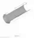
BRIEF DESCRIPTION OF THE DRAWINGSFIG. 1 is a perspective view of a first embodiment of the present invention;
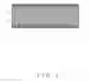
FIG. 2 is an enlarged view of the first embodiment of the present invention;
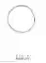
FIG. 3 is a cross sectional view of the first embodiment of the present invention;
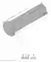
FIG. 4 is a perspective view of a second embodiment of the present invention;
FIG. 5 is a perspective view of a prior art, and
FIG. 6 is a cross sectional view of FIG. 5.
DETAILED DESCRIPTION OF THE PREFERRED EMBODIMENTSA radiation tube structure of the present invention, as shown in FIGS. 1 and 2, comprises a mental tube 1 broached with lengthwise grooves 2 and continuous circular grooves 3 on the internal wall. (The circular grooves 3 may be milled in circle formed independently or in a spiral method.) The circular grooves 3 cross the lengthwise grooves 2 to form grids on the internal wall.
To practice, as shown in FIG. 3, coolant fluid flows through the interior of the tube 1. The grids formed by the lengthwise grooves 2 and the circular grooves 3 increase the surface. Thus, the coolant fluid will be in contact with larger surface. This helps the coolant fluid to spread more evenly on the surface of the internal wall of the tube 1. The capillary effect will reach to the best effect in dissipating heat within the tube 1.
FIG. 4 shows a second embodiment of the present invention. The internal wall of a tube 4 is milled with circular grooves 5 in one direction. After this process, the internal wall of the tube 4 is milled with circular grooves in an opposing direction to form many a rhombus grid. These grooves 5 and 6 increase the contact surface to help for dissipating heat.
Claims
1. A radiation tube structure being a mental tube formed with lengthwise grooves and circular grooves along an internal wall of said tube, said lengthwise grooves and circular grooves forming crossing heat dissipation grooves.
2. The radiation tube structure, as recited in claim 1, wherein said circular grooves are formed in a spiral shape within said tube.
3. The radiation tube structure, as recited in claim 1, wherein said circular grooves are formed in circular and independent with each other.
4. A radiation tube structure being a mental tube formed with net grooves along an internal wall of said tube to form crossing heat dissipation grooves.
Images & Drawings included:


Sources:
- United States Patent and Trademark Office - verify current appl. status at the USPTO↗
Similar patent applications:
Recent applications in this class:
- » 20240318925 2024-09-26
REACTOR FIN INSERT DESIGN - » 20240302112 2024-09-12
ANTI-FREEZING PIPE HAVING BUILT-IN TUBE AND HIGH-EFFICIENCY HEAT EXCHANGER USING THE SAME - » 20240255233 2024-08-01
HEAT EXCHANGER, POWER CONVERSION DEVICE INCLUDING HEAT EXCHANGER, AND METHOD FOR MANUFACTURING INNER FIN FOR HEAT EXCHANGER - » 20240191953 2024-06-13
HEAT EXCHANGER TUBE WITH HIGH HEAT TRANSFER AND LOW PRESSURE DROP - » 20240191952 2024-06-13
Process cooling rod - » 20240175644 2024-05-30
METHOD FOR PRODUCING PIPES HAVING TOPOGRAPHIC INNER STRUCTURES - » 20240035754 2024-02-01
HEAT EXCHANGE TUBE AND HEAT EXCHANGER HAVING SAME - » 20230392879 2023-12-07
Process cooling rod - » 20230314092 2023-10-05
Varying topology heat sinks - » 20230314091 2023-10-05
Varying topology heat sinks