Assembly for connecting two thermoplastic tubular elements
US20050126702A1
2005-06-16
10/520,165
2003-07-07
Abstract:
The invention concerns an assembly for fixing two thermally non-expansible thermoplastic tubular elements (1, 2) characterized in that it comprises a first thermally non-expansible thermoplastic tubular element (1) including a fixing zone (4) on the inner wall of one of its ends, a second thermally non-expansible thermoplastic tubular element including a fixing zone (6) on the outer wall of one of its ends, the diameter of the inner wall of said end of the first tubular element (1) being larger than the diameter of the outer wall of said end of the second tubular element (2) so as to define, when the two ends overlap, an annular space between said inner and outer walls, the assembly further comprising a thermoplastic sleeve (3) adapted to be housed in the annular space, said sleeve (3) containing a conductive element (5) capable of being induction-heated.
Interested in similar patents?
Get notified when new applications in this technology area are published.
Classification:
F16L47/03 » CPC main
Connecting arrangements or other fittings specially adapted to be made of plastics or to be used with pipes made of plastics; Welded joints; Adhesive joints Welded joints with an electrical resistance incorporated in the joint
B29C65/3644 » CPC further
Joining of preformed parts ; Apparatus therefor by heating, with or without pressure using heated elements which remain in the joint, e.g. "verlorenes Schweisselement" heated by induction characterised by the type of elements heated by induction which remain in the joint being a ribbon, band or strip
B29C65/4815 » CPC further
Joining of preformed parts ; Apparatus therefor using adhesives, i.e. using supplementary joining material; solvent bonding characterised by the type of adhesives; Non-reactive adhesives, e.g. physically hardening adhesives Hot melt adhesives, e.g. thermoplastic adhesives
B29C65/5057 » CPC further
Joining of preformed parts ; Apparatus therefor using adhesives, i.e. using supplementary joining material; solvent bonding using adhesive tape, e.g. thermoplastic tape; using threads or the like positioned between the surfaces to be joined
B29C66/1122 » CPC further
General aspects of processes or apparatus for joining preformed parts; General aspects dealing with the joint area or with the area to be joined; Particular design of joint configurations particular design of the joint cross-sections; Joint cross-sections comprising a single joint-segment, i.e. one of the parts to be joined comprising a single joint-segment in the joint cross-section; Single lapped joints Single lap to lap joints, i.e. overlap joints
B29C66/5221 » CPC further
General aspects of processes or apparatus for joining preformed parts; General aspects of joining tubular articles; General aspects of joining long products, i.e. bars or profiled elements; General aspects of joining single elements to tubular articles, hollow articles or bars; General aspects of joining several hollow-preforms to form hollow or tubular articles; Joining tubular articles, profiled elements or bars; Joining single elements to tubular articles, hollow articles or bars; Joining several hollow-preforms to form hollow or tubular articles; Joining tubular articles, bars or profiled elements; Joining tubular articles for forming coaxial connections, i.e. the tubular articles to be joined forming a zero angle relative to each other
B29C66/5229 » CPC further
General aspects of processes or apparatus for joining preformed parts; General aspects of joining tubular articles; General aspects of joining long products, i.e. bars or profiled elements; General aspects of joining single elements to tubular articles, hollow articles or bars; General aspects of joining several hollow-preforms to form hollow or tubular articles; Joining tubular articles, profiled elements or bars; Joining single elements to tubular articles, hollow articles or bars; Joining several hollow-preforms to form hollow or tubular articles; Joining tubular articles, bars or profiled elements; Joining tubular articles involving the use of a socket
B29C66/73921 » CPC further
General aspects of processes or apparatus for joining preformed parts characterised by the composition, physical properties or the structure of the material of the parts to be joined; Joining with non-plastics material characterised by the intensive physical properties of the material of the parts to be joined, by the optical properties of the material of the parts to be joined, by the extensive physical properties of the parts to be joined, by the state of the material of the parts to be joined or by the material of the parts to be joined being a thermoplastic or a thermoset characterised by the material of the parts to be joined being a thermoplastic or a thermoset characterised by the material of at least one of the parts being a thermoplastic characterised by the materials of both parts being thermoplastics
B29C65/368 » CPC further
Joining of preformed parts ; Apparatus therefor by heating, with or without pressure using heated elements which remain in the joint, e.g. "verlorenes Schweisselement" heated by induction characterised by the composition of the elements heated by induction which remain in the joint being metallic with a polymer coating
Description
The present invention relates to an assembly for fusion bonding two thermally nonexpansible thermoplastic tubular elements. The invention also relates to a method of bonding thermoplastic tubular elements together using said assembly.
Assemblies for bonding two thermally nonexpansible thermoplastic tubular elements, as a result of their contact zones being fused together by heating, are known. The heating may be carried out by creating a magnetic field (induction heating) or a current (resistance heating) in a conducting element incorporated in one of the thermoplastic tubular elements. Such systems are disclosed in patent documents WO 80/02124, EP 0 480 053 A1, U.S. Pat. No. 4,634,844 and WO 81/02405.
The systems of the prior art are relatively expensive and complicated to produce owing to the insertion of the conducting element into the tubular element.
One of the objects of the present invention is to simplify the assemblies for fusion bonding two tubular elements together.
Another object relates to the possibility of using existing tubular elements which do not contain conducting elements in their bonding zones but which, at the cost of a very simple modification of the internal diameter of one of the tubular elements, can be fusion bonded together.
These objects are achieved by producing an assembly for fusion bonding two thermally nonexpansible thermoplastic tubular elements together, characterized in that it comprises a first thermally nonexpansible thermoplastic tubular element having a bonding zone on the internal wall of one of its ends, a second thermally nonexpansible thermoplastic tubular element having a bonding zone on the external wall of one of its ends, the diameter of the internal wall of said end of the first tubular element being greater than the diameter of the external wall of said end of the second tubular element so as to define, when the two ends overlap, an annular space between said internal and external walls, the assembly furthermore including a thermoplastic sleeve suitable for being housed in said annular space, said sleeve containing a conducting element that can be heated by induction.
The term “thermoplastic” should be understood to mean any plastic that melts under the action of heat, or at the very least softens sufficiently to be able to be formed an infinite number of times without its properties being modified. By way of nonlimiting examples of thermoplastics that can be used within the context of the present invention, mention may be made of polypropylene, polybutene, polyethylene or any other similar synthetic resin.
The tubular elements used within the context of the present invention may have any shape. One of the elements may be a coupler, an angled element or a T-shaped element.
The invention also relates to a method of fusion bonding two tubular elements using the assembly described above, characterized by the following steps:
-
- the diameter of the internal wall of the first tubular element is adjusted so as to be able to place the sleeve in said annular space;
- the sleeve is placed around the end of the second tubular element;
- the end of the second tubular element and of the sleeve is introduced into the end of the first tubular element; and
- the bonding zone is heated and fused by induction heating.
The diameter of the internal wall of the first tubular element may be adjusted very simply. A coupler of smaller diameter than that desired is initially chosen and this coupler is then enlarged by means of a conventional machine.
An illustrative example of the invention will be described in greater detail by means of the following figures:
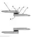
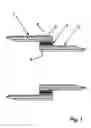
FIG. 1 shows a longitudinal section of an assembly for bonding two tubular elements together; and
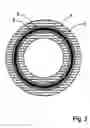
FIG. 2 shows a cross section of the assembly of FIG. 1.
The assembly illustrated in FIGS. 1 and 2 consists of a first thermoplastic tubular element 1 and a second thermoplastic tubular element 2, the outside diameter of the second tubular element 2 being smaller than the inside diameter of the first tubular element 1. The difference in diameter between the two tubular elements 1, 2 may for example be around 4 mm. The annular space created between the two tubular elements 1, 2 is occupied by a thermoplastic sleeve 3 that includes a ring-shaped conducting element 5. The thickness of the conducting element 5 may be of the order of 1 mm. The thickness of the thermoplastic sleeve 3 may be 2 mm. The internal diameter of the thermoplastic sleeve 3 may be around 40 mm and its length around 15 mm.
Once the assembly is in place, the conducting element 5 is heated by induction heating, therefore causing the thermoplastic material constituting the sleeve 3 and the adjacent walls of the tubular elements 1, 2 to melt. After cooling, the assembly forms a uniform block thermoplastic, ensuring that the tubular elements 1, are bonded together.
Claims
1. An assembly for fusion bonding two thermally nonexpansible thermoplastic tubular elements (1, 2) together, characterized in that it comprises a first thermally nonexpansible thermoplastic tubular element (1) having a bonding zone (4) on the internal wall of one of its ends, a second thermally nonexpansible thermoplastic tubular element (2) having a bonding zone (6) on the external wall of one of its ends, the diameter of the internal wall of said end of the first tubular element (1) being greater than the diameter of the external wall of said end of the second tubular element (2) so as to define, when the two ends overlap, an annular space between said internal and external walls, the assembly furthermore including a thermoplastic sleeve (3) suitable for being housed in said annular space, said sleeve (3) containing a conducting element (5) that can be heated by induction.
2. The assembly as claimed in the preceding claim, characterized in that the first tubular element is a coupler.
3. A method of fusion bonding two tubular elements together using the assembly of claim 1, characterized by the following steps:
the diameter of the internal wall of the first tubular element is adjusted so as to be able to place the sleeve in said annular space;
the sleeve is placed around the end of the second tubular element;
the end of the second tubular element and of the sleeve is introduced into the end of the first tubular element; and
the bonding zone is heated and fused by induction heating.
Images & Drawings included:
Sources:
- United States Patent and Trademark Office - verify current appl. status at the USPTO↗
Recent applications in this class:
- » 20240019066 2024-01-18
Methods of Joining or Repairing Lined Pipes and Associated Apparatus - » 20230417355 2023-12-28
Weldable half-shell - » 20220341528 2022-10-27
Electrofusion joint - » 20220018479 2022-01-20
Apparatus and method for electrofusion welding of reinforced thermosetting resin pipe joints - » 20190316721 2019-10-17
Methods of joining or repairing lined pipes and associated apparatus - » 20190128459 2019-05-02
Connection device for pipe elements - » 20190128458 2019-05-02
Continuous fiber reinforced composite and metal electrofusion coupler - » 20180363822 2018-12-20
Electrofusion fitting methods - » 20180216772 2018-08-02
Pipe coupler and coupling methods - » 20170299103 2017-10-19
ELECTROWELDABLE SADDLE-TYPE FITTING AND RELATIVE WELDING METHOD