Method and apparatus for laterally positioning a moving web
US20050127125A1
2005-06-16
10/966,176
2004-10-15
Abstract:
An apparatus for laterally displacing a moving web without distorting or creasing the web and without need for free lead-in distance beforehand to achieve these results. Key elements in apparatus include two 45° turning bars, one each at entry and exit, which are stationary and laterally-movable, respectively. Position of web is monitored at exit of apparatus by edge sensor(s), and an actuator moves exit turning bar to displace web in direction called for by said sensor(s).
Interested in similar patents?
Get notified when new applications in this technology area are published.
Classification:
B65H23/038 » CPC main
Registering, tensioning, smoothing or guiding webs transversely; Controlling transverse register of web by rollers
B65H23/32 » CPC further
Registering, tensioning, smoothing or guiding webs longitudinally Arrangements for turning or reversing webs
B65H2301/3113 » CPC further
Handling processes for sheets or webs; Orientation, displacement, position of the handled material; Features of transport path for transport path in plane of handled material, e.g. geometry vertical
B65H2301/3125 » CPC further
Handling processes for sheets or webs; Orientation, displacement, position of the handled material; Features of transport path for transport path involving at least two planes of transport forming an angle between each other T-shaped
Description
CROSS-REFERENCE TO RELATED APPLICATIONSThis application claims the benefit of provisional patent application No. 60/511,897 filed Oct. 16, 2003, by the present inventor, the contents of which are incorporated by reference herein in their entirety.
FIELD OF INVENTIONThis invention relates to webs of textile fabric, paper, and others, specifically to an improved way of positioning, and controlling the lateral movement of, such webs.
BACKGROUND OF THE INVENTION/PRIOR ARTMoving webs—textile fabric, paper, film, foil, nonwoven material, and others—are printed, laminated, coated, washed, dyed, etc., in continuous processes.
The lateral position of the moving web being processed must be controlled in such a way that the web is either centered or that one of the edges is precisely controlled, without undue distortion and resultant creases in the web.
In addition to being presented to the entry of a process machine in a laterally-controlled condition, a moving web which may have wandered from its desired position must be re-entered at intermediate locations in the process, e.g., in continuous textile washing, dyeing and finishing ranges which process hundreds of yards of fabric simultaneously.
All of the methods currently available for lateral positioning and control of a moving web—steering rollers, cammed slats, edge nip rollers, among others—involve some degree of distortion of the web as its lateral position is changed. The amount of correction possible without unacceptable distortion and resultant creases is limited by the free length of web ahead of the guiding method (at least 1 to 1½ times the fabric width).
45° turning bars, which are well-known and in use for turning over or changing the direction of a web, are essential elements in this invention. In the experience of the present inventor, a turning bar has never been used to precisely control the lateral position of a moving web.
SUMMARY OF THE INVENTIONThe present invention offers advantages over and alternatives to the known art by providing an apparatus and method which laterally positions a web without causing any distortion or introduction of creases and without the need for any free length of fabric beforehand, regardless of web width. The amount of repositioning possible is limited only by the length of the apparatus components. Floor space requirement in the direction of web flow is minimal.
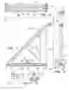
BRIEF DESCRIPTION OF DRAWINGSFIG. 1 illustrates the present invention as it would be seen with direction of web flow toward the observer.
FIG. 2 illustrates the apparatus as it would be seen from the left side of FIG. 1, with web flow to the observer's left.
FIG. 3 illustrates the apparatus as it would be seen from above, with web flow downward.
FIG. 4 illustrates path of the web through the apparatus.
DETAILED DESCRIPTION OF DRAWINGSIn FIG. 1, FIG. 2, and FIG. 3, in a preferred arrangement, the apparatus includes:
-
- Entry idler roll 10 whose position is fixed and whose width is sufficient to contain entering web over the range of its varying lateral position
- Fixed turning bar 12, oriented at 45° with respect to idler roll 10, whose length is sufficient to contain entering web over the range of its varying lateral position
- Fixed structural framework 14 for support of idler roll 10 and turning bar 12, supporting members for which must be narrow enough to avoid contact with the moving web
- Vertical idler roll 16, exit turning bar 18 also oriented at 45°, and exit idler roll 20, the three of which are mounted on structural framework 22, all of which are laterally movable as a unit with respect to entry idler roll 10, turning bar 12, and framework 14
- Lengths of idler roll 16 and turning bar 18 are sufficient to contain entering web over the range of varying its lateral position, while length of exit idler roll 20 is sufficient to contain maximum width of web being processed.
- Framework 22 is mounted on wheels 24 at each end for easy lateral movement. Unit is stabilized at upper corner via slide 26 attached to movable frame.
- Edge sensors 28, photoelectric or the like, mounted independently, which monitor position of edges of moving web downstream of idler roll 20 for centering the web or for controlling either edge
- Actuating system 30 for laterally moving idler roll 16, turning bar 18, idler roll 20, and framework 22 with respect to entry idler roll 10, turning bar 12, and framework 14, on command from a control system 36, PLC or the like, receiving input from sensor(s) 28.
- A preferred actuating system makes use of motor-reducer and pulley arrangement 30, or the like, mounted on fixed framework 14 which drives timing belt 32 secured at each end of movable framework 22, causing turning bar 18 to move in direction required to correct error in web edge position detected by sensor(s) 28.
The path of web 34 through apparatus as moving section maintains position called for by the sensor(s) 28 is shown on FIG. 4.
By way of example only, and not in such a way as to be limited to the following dimensions, in one preferred embodiment of the invention for handling a flexible web (such as woven textile fabric or paper) up to 100 inches wide, fixed framework 14 and movable framework 22 are made of 3×1×⅛ inch cold-finished rectangular steel tubing, welded construction; entry idler roll 10, vertical idler roll 16, and exit idler roll 20 are made of 3 inch diameter×⅛ inch wall stainless steel ground and polished roll quality tubing; and fixed turning bar 12 and movable turning bar 18 are made of 3 inch diameter×{fraction (1/16)} inch wall welded steel tubing.
For webs of more or less flexibility and width, component size requirements and their construction will vary accordingly.
Turning bars may be covered with low friction abrasion-resistant plastic such as ultra high molecular weight polyethylene to reduce web tension or, for very low tension, may be perforated to allow introduction of compressed air supplied from a regenerative blower or compressor. If web is plastic or contains synthetic fibers, static electricity generated as web slides over turning bars may be neutralized by any one of many well-known means.
In another variation, vertical idler roll 16 may be mounted on fixed (entry) section instead of on movable (exit) section.
In another variation, assembled unit may be oriented horizontally instead of vertically.
Claims
1. An apparatus for laterally displacing a moving web without distorting the web, which result is achieved without need for free lead-in distance before web enters apparatus, or without creasing said web, the apparatus comprising, sequentially in direction of web flow: entry idler roll and 45° entry turning bar, both mounted on stationary entry framework; vertical idler roll, 45° exit turning bar, and exit idler roll, the three of which are mounted on laterally-movable exit framework; actuator for causing said exit framework and its turning bar to move as directed by signal from web edge sensors, which movement will cause web to be laterally displaced
2. An apparatus as in claim 1. in which vertical idler roll is mounted on stationary entry framework rather than on movable exit framework
3. An apparatus as in claim 1. or claim 2. in which turning bars are perforated, or porous, rather than of solid construction, and into which compressed air may be introduced to allow web to float over bars under very low tension
4. An apparatus as in claim 1., claim 2. or claim 3. which is oriented horizontally rather than vertically
5. An apparatus as in claim 1., claim 2. or claim 3. in which movable exit turning bar is oriented 90° with respect to stationary entry bar, rather than parallel to stationary entry bar, for turning the web over in addition to displacing it.
Images & Drawings included:


Sources:
- United States Patent and Trademark Office - verify current appl. status at the USPTO↗
Recent applications in this class:
- » 20250145401 2025-05-08
Position Roller for Web Meander Control - » 20240391722 2024-11-28
COMPLIANT SYSTEM WITH FIN - » 20220340387 2022-10-27
Marking system for rolled materials having transparency or translucence to pinpoint a tear - » 20220219929 2022-07-14
Web Transport Control Device - » 20220219928 2022-07-14
Rotary frame construction for web transport control devices - » 20210053785 2021-02-25
Roller for guiding and/or width stretching of a running material web - » 20200369486 2020-11-26
FLEXIBLE SUBSTRATE ADJUSTING DEVICE - » 20190367310 2019-12-05
Device and method for aligning material sheets - » 20180346274 2018-12-06
Position control system and method - » 20180282098 2018-10-04
Recording apparatus