Bracket assembly
US20050127247A1
2005-06-16
10/737,048
2003-12-16
✅ Patent granted
US 7,963,498 B2
2011-06-21
-
-
Amy J Sterling
2028-05-27
Abstract:
An assemblage (8) comprises an electrical connector (10) having body (12) with a tubular projection (14) having a push-through portion (16) having a first diameter and an engaging portion (18) having a second diameter larger than the first diameter. A support (20) for the electrical connector (10) has a major part 22 that is substantially rigid and includes an aperture (24) formed by a plurality of deflectable spokes (26). The aperture (24) has a center opening (28) with a third diameter greater than the first diameter and less than the second diameter, whereby the tubular projection push-through portion (16) slides through the aperture (24) and the spokes (26) engage the second diameter of the engaging portion (18) and mount the electrical connector (10) with the support (20).
Inventors:
- Douglas G. Seymour 15 🇺🇸 York, PA, United States
- Michael J. Swantner 12 🇺🇸 Warren, PA, United States
- David Humphrey 1 🇺🇸 York, PA, United States
Assignee:
- OSRAM SYLVANIA INC. 806 🇺🇸 Danvers, MA, United States
Interested in similar patents?
Get notified when new applications in this technology area are published.
Classification:
F16M13/00 IPC
Other supports for positioning apparatus or articles ; Means for steadying hand-held apparatus or articles
H01R13/74 » CPC main
Details of coupling devices of the kinds covered by groups or -; Means for mounting coupling parts to apparatus or structures, e.g. to a wall Means for mounting coupling parts in openings of a panel
F16B9/07 » CPC further
Connections of rods or tubular parts to flat surfaces at an angle involving plastic or elastic deformation when assembling
H01R9/16 » CPC further
Structural associations of a plurality of mutually-insulated electrical connecting elements, e.g. terminal strips or terminal blocks; Terminals or binding posts mounted upon a base or in a case; Bases therefor Fastening of connecting parts to base or case; Insulating connecting parts from base or case
Description
TECHNICAL FIELDThis invention relates to electrical connectors and more particularly to mounted electrical connectors.
BACKGROUND ARTSome electrical connectors, particularly for automotive use, have included a machined body of, for example, brass or nickel plated steel that had at least on portion that was press-fitted into a bracket. It was found that the press-fitting process occasionally skived small slivers of plating material off the inserted part when assembled to the bracket, and these skived slivers could cause a short circuit if they found their way into the insert. Subsequent attempts to relieve this problem eliminated the machined body in favor of a cast body of, for example, aluminum or zinc alloy. However, it was found that the using the cast body caused other problems because, when assembled to a bracket and subsequently heated in a soldering process, the heat caused a relaxing of the cast material causing the bracket to loosen and creating grounding problems.
DISCLOSURE OF INVENTIONIt is, therefore, an object of the invention to obviate the disadvantages of the prior art.
It is another object of the invention to enhance electrical connectors.
It is yet another object of the invention to enhance an assemblage of connector and a support therefor.
These objects are accomplished, in one aspect of the invention, by the provision of an assemblage that comprises an electrical connector having body with a tubular projection having a push-through portion with a first diameter and an engaging portion having a second diameter larger than the first diameter. A support for the electrical connector has a major part that is substantially rigid and includes an aperture formed by a plurality of deflectable spokes. The aperture has a center opening with a third diameter that is greater than the first diameter and less than the second diameter, whereby the tubular projection push-through portion slides through the aperture and the spokes engage the second diameter of the engaging portion and mount the electrical connector with the support.
The spokes function as flexible beams during the assembly process which deflect to accept the insert and remain under load after the assembly is competed. When heat is applied for the soldering process and the casting relaxes, the beam dig into the cast insert and provide adequate support which insures a good ground. Further, the elimination of the skiving problem reduces the possibility of electrical short circuits.
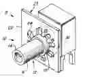
BRIEF DESCRIPTION OF THE DRAWINGSFIG. 1 is a perspective view of an assemblage of electrical connector and support in accordance with an aspect of the invention;
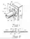
FIG. 2 is an elevational, section view of the support; and
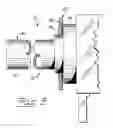
FIG. 3 is an elevational view of an electrical connector and support, par in section.
BEST MODE FOR CARRYING OUT THE INVENTIONFor a better understanding of the present invention, together with other and further objects, advantages and capabilities thereof, reference is made to the following disclosure and appended claims in conjunction with the above-described drawings.
Referring now to the drawings in greater detail, there is shown in FIG. 1 an assemblage 8 comprised of an electrical connector or insert 10 having body 12 with a tubular projection 14 having a push-through portion 16 having a first diameter and an engaging portion 18 having a second diameter larger than the first diameter. A support 20 for the electrical connector has a major part 22 that is substantially rigid and includes an aperture 24 formed by a plurality of deflectable spokes or beams 26. The support is preferably made from Sn/Pb plated steel. The aperture 24 has a center opening 28 with a third diameter that is greater than the first diameter and less than the second diameter, whereby the tubular projection push-through portion 16 slides through the aperture 24 and the spokes 26 engage the second diameter of the engaging portion 18 and mount said electrical connector 10 with the support 20.
A stop 30 (see particularly FIG. 3) which, in a preferred embodiment, can be another diameter formed behind the engaging portion 18, limits the amount of insertion of the electrical connector into the support 20.
Also, in a preferred embodiment, the spokes 26 are formed to diverge away from the plane of the major part 22 of the support 20 to aid in the insertion process.
Because of the flexing capability of the spokes 26, skiving is eliminated, thus greatly reducing the possibility of short circuits developing.
Additionally, upon heating, the spokes will actually dig into the cast insert body as it relaxes from the heat applied during a soldering operation allowing the support/insert interface to remain tightly assembled and provide good and continuing ground connection for the connector.
While there have been shown and described what are at present considered to be the preferred embodiments of the invention, it will be apparent to those skilled in the art that various changes and modification can be made herein without departing from the scope of the invention as defined by the appended claims.
Claims
1. An assemblage comprising:
an electrical connector having a metal body with a tubular projection having a push-through portion having a first diameter and an engaging portion having a second diameter larger than said first diameter;
and a metal support having a major part that is substantially rigid and includes an aperture formed by a plurality of deflectable spokes, said aperture having a center opening with a third diameter greater than said first diameter and less than said second diameter, whereby said tubular projection push-through portion slides through said aperture and said spokes engage said second diameter of said engaging portion and mount said electrical connector with said support.
2. The assemblage of claim 1 wherein a stop associated with said second diameter limits the amount of movement possible for said support.
3. The assemblage of claim 2 wherein said spokes of said support diverge away from the plane of said major part of said support.
Images & Drawings included:
Sources:
- United States Patent and Trademark Office - verify current appl. status at the USPTO↗
Similar patent applications:
- » 20250235972
BRACKETS, BRACKET ASSEMBLIES, MACHINERY ARRANGEMENTS AND SEMICONDUCTOR PROCESSING SYSTEMS INCLUDING BRACKETS AND BRACKET ASSEMBLIES, AND METHODS OF MAKING BRACKET ASSEMBLIES - » 20240164043
Bracket assembly for riser bracket assembly - » 20190085899
Bearing cup for a bicycle bottom bracket assembly and bicycle bottom bracket assembly comprising said bearing cup - » 18629587
Bracket assembly and fan with bracket assembly - » 20150342707
Self-uprighting orthodontic bracket assembly and a method of using the bracket assembly - » 20060193424
Clamp for feedwater sparger end bracket assemblies and method of preventing separation of feedwater sparger end bracket assemblies - » 20070011859
Method to assemble components using brackets and bracketed assemblies with bracket furniture components - » 20230380096
Bracket assembly and bracket structure and server assembly - » 20220285826
ENCLOSURES FOR CELLULAR BASE STATION ASSEMBLIES AND BRACKET ASSEMBLIES FOR MOUNTING SAME - » 20080074836
Bracket assembly for disk drive and a method of assembling a bracket to an enclosure for preventing resonance
Recent applications in this class:
- » 20250273915 2025-08-28
ELECTRICAL WIRING DEVICES FOR USE IN KITCHEN/BATHROOM COUNTERTOPS - » 20250253597 2025-08-07
Connector Housing Assembly and Connector - » 20250202172 2025-06-19
SOCKET BOX FOR FLUSH-MOUNTING IN A FLOOR SURFACE AND INSTALLATION METHOD - » 20250132528 2025-04-24
WALL SOCKET - » 20250105564 2025-03-27
ELECTRICAL POWER CONNECTOR - » 20250079776 2025-03-06
RELAY CONNECTOR - » 20240322505 2024-09-26
ELECTRICAL CONNECTION DEVICE AND ELECTRICAL CONNECTION DEVICE ASSEMBLY - » 20240162668 2024-05-16
GROMMET AND INLET ASSEMBLY - » 20240120692 2024-04-11
ELECTRICAL RECEPTACLE ASSEMBLY WITH OUTWARD-BIASING FACEPLATE - » 20240106175 2024-03-28
Connector Assembly and Electrical Connection Assembly
Recent applications for this Assignee:
- » 20170094750 2017-03-30
Lighting system that self detects the relative physical arrangement of its sources - » 20170094738 2017-03-30
Controller for a phase cut dimmable LED driver - » 20170093491 2017-03-30
Adaptive baud rate in light-based communication - » 20170093490 2017-03-30
Sub-sampling raster lines in rolling shutter mode for light-based communication - » 20170093489 2017-03-30
Reconstructing light-based communication signals captured with a rolling shutter image capture device - » 20170093280 2017-03-30
Digitally compensated hysteretic power supply with enhanced resolution - » 20170093159 2017-03-30
Dynamic control of switching frequency in a switch mode power converter - » 20170089542 2017-03-30
Lamp optic for use in LED-based lamp - » 20170067612 2017-03-09
Vehicle low-beam headlamp with concave reflector and sub-reflector having two concave reflecting surfaces - » 20170063240 2017-03-02
DC-DC FLYBACK CONVERTER WITH PRIMARY SIDE AUXILIARY VOLTAGE OUTPUT