Fuse seat for filter
US20050128045A1
2005-06-16
10/735,763
2003-12-16
✅ Patent granted
US 7,019,612 B2
2006-03-28
-
-
Anatoly Vortman
2024-08-18
Abstract:
A fuse seat filter for filter is disclosed. The fuse seat has an insertion seat and a cavity at the bottom section of the insertion seat characterized in that a positive and a negative conductive plate are respectively mounted to the two lateral sides of the cavity and the bottom section of the cavity for contacting with the positive and negative terminal of the fuse, and one lateral wall of the cavity is provided with a guiding slot and the two sides of the slot wall of the guiding slot are provided with a positioning recess and one lateral side of the seat body is provided with two engaging slot for engaging one end of the fuse, and between two engaging slot, a support block is mounted, and one lateral side of the support block is provided with sliding plate allowing sliding movement within the guiding slot, and the sliding plate has a positing protruded block for engagement at the positioning slot. The seat body and the insertion seat are separable so that a fuse can be loaded or unloaded and the large volume is greatly reduced.
Interested in similar patents?
Get notified when new applications in this technology area are published.
Classification:
H01H85/20 IPC
Protective devices in which the current flows through a part of fusible material and this current is interrupted by displacement of the fusible material when this current becomes excessive; Details Bases for supporting the fuse; Separate parts thereof
H01R24/66 » CPC main
Two-part coupling devices, or either of their cooperating parts, characterised by their overall structure with pins, blades or analogous contacts and secured to apparatus or structure, e.g. to a wall
H01H85/547 » CPC further
Protective devices in which the current flows through a part of fusible material and this current is interrupted by displacement of the fusible material when this current becomes excessive; Protective devices wherein the fuse is carried, held, or retained by an intermediate or auxiliary part removable from the base, or used as sectionalisers with sliding fuse carrier
H01R13/68 » CPC further
Details of coupling devices of the kinds covered by groups or -; Structural association with built-in electrical component with built-in fuse
H01R2103/00 » CPC further
Two poles
H01H85/22 IPC
Protective devices in which the current flows through a part of fusible material and this current is interrupted by displacement of the fusible material when this current becomes excessive; Details Intermediate or auxiliary parts for carrying, holding, or retaining fuse, co-operating with base or fixed holder, and removable therefrom for renewing the fuse
H01R33/95 IPC
Coupling devices specially adapted for supporting apparatus and having one part acting as a holder providing support and electrical connection via a counterpart which is structurally associated with the apparatus, e.g. lamp holders; Separate parts thereof; Holders with built-in electrical component with fuse; with thermal switch
Description
BACKGROUND OF THE INVENTION(a) Technical Field of the Invention
The present invention relates to a fuse seat, and in particular, to a fuse seat for filter which is easily operated, and conveniently installed, low cost in production and has a small volume.
(b) Description of the Prior Art
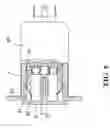
FIGS. 1 and 2 show a conventional fuse seat for filter comprising an insertion seat 1 having a drawer-like seat body 2.
The insertion seat 1 has a cavity 10 for the holding of the seat body 2, and within the cavity 10, there are two sets of positive and negative conductive plate 11 linked to the electronic components 3 at the other side of the insertion seat 1. The electronic components 3 are externally covered by a metallic housing 30. The two lateral walls of the cavity 10 are provided with a sliding slot 12 for the sliding and engagement of the two lateral sides of the seat body.
The seat body 2 has a chamber 20 for the holding of fuse 31. The two lateral sides of the seat body 2 are each protrudingly provided with a sliding block 21 so that the sliding block 21 is slidably engaged within the sliding slot 12.
The sliding block 21 is slidably engaged within the sliding slot 12 and the seat body 2 at the insert seat 1 is formed as a drawer and the fuse 31 can be inserted to the cavity 10.
The drawbacks of the convention fuse seats are:
-
- (1) Inconvenient in operation:
- As the sliding block 21 will slide and be engaged at the other end of the sliding slot 12, the seat bot 2 cannot be fully withdrawn. Thus, if the fuse 31 is to be loaded the fuse 31 has to be at an inclined position to be pressed into the seat body 2. As a result, the fuse 31 may be damaged due to excessive force on cannot be fully pressed into the seat body 2. If the fuse 31 is to be unloaded, the seat body 2 cannot be withdrawn and the fuse 31 may not be unloaded, as shown in FIG. 2.
- (2) The structure is complicated and installation process is laborious. The two sides of the insertion seat 1 are provided with a sliding slot 12 for the sliding block 21 to be slidably engaged, and the mounting position of the positive and negative plate 11 in the cavity 10 will be restricted. Thus, the structure is very complicated and the cost of production is greatly increased. Further, the engageably sliding of the sliding block 21 into the sliding slot 12 is not easy and therefore the installation is not convenient.
- (3) Large volume and occupy space. The two sides of the insertion seat 1 should provide an appropriate sliding distance for the sliding block. Thus, an appropriate length for the sliding slot 12 is needed and therefore the size of the insertion seat 1 has to be extended and the volume of the insertion will be increased. Thus, a large space is needed.
- (1) Inconvenient in operation:
Accordingly, it is an object of the present invention to provide a fuse seat for filter, which mitigates the above drawbacks.
SUMMARY OF THE INVENTIONAccordingly, it is an object of the present invention to provide a fuse seat for filter having an insertion seat and a cavity at the bottom section of the insertion seat characterized in that a positive and a negative conductive plate are respectively mounted to the two lateral sides of the cavity and the bottom section of the cavity for contacting with the positive and negative terminal of the fuse, and one lateral wall of the cavity is provided with a guiding slot and the two sides of the slot wall of the guiding slot are provided with a positioning recess and one lateral side of the seat body is provided with two engaging slot for engaging one end of the fuse, and between two engaging slot, a support block is mounted, and one lateral side of the support block is provided with sliding plate allowing sliding movement within the guiding slot, and the sliding plate has a positing protruded block for engagement at the positioning slot. The seat body and the insertion seat are separable so that a fuse can be loaded or unloaded and the large volume is greatly reduced.
The foregoing object and summary provide only a brief introduction to the present invention. To fully appreciate these and other objects of the present invention as well as the invention itself, all of which will become apparent to those skilled in the art, the following detailed description of the invention and the claims should be read in conjunction with the accompanying drawings. Throughout the specification and drawings identical reference numerals refer to identical or similar parts.
Many other advantages and features of the present invention will become manifest to those versed in the art upon making reference to the detailed description and the accompanying sheets of drawings in which a preferred structural embodiment incorporating the principles of the present invention is shown by way of illustrative example.
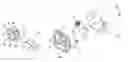
BRIEF DESCRIPTION OF THE DRAWINGSFIG. 1 is a perspective exploded view of a conventional fuse seat for filter.
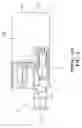
FIG. 2 is a partial sectional view of a conventional fuse seat for filter.
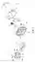
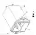
FIG. 3 is a perspective exploded view of a fuse seat for filter of the present invention.
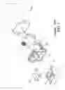
FIG. 4 is a perspective view of the fuse seat for filter of the present invention.
FIG. 5 is a sectional view showing the engaging of the fuse seat to the fuse seat of the present invention.
FIG. 6 is a schematic view showing the combination of the positioning protruded block with the positioning slot and the engaging plate with the engaging slot of the present invention.
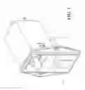
FIG. 7 is a perspective view of another preferred embodiment of the present invention.
DETAILED DESCRIPTION OF THE PREFERRED EMBODIMENTThe following descriptions are of exemplary embodiments only, and are not intended to limit the scope, applicability or configuration of the invention in any way. Rather, the following description provides a convenient illustration for implementing exemplary embodiments of the invention. Various changes to the described embodiments may be made in the function and arrangement of the elements described without departing from the scope of the invention as set forth in the appended claims.
Referring to FIGS. 3 to 5, there is shown a fuse seat for filter comprising an insertion seat 4 having a drawer-like base seat 5.
The insertion seat 4 has a cavity 40 for holding the seat body 5. The cavity 40 contains two sets of positive and negative plates 41, and the positive and negative plates 41 are respectively mounted at the two sides and the bottom section for respectively contacting with the positive and negative terminal of the fuse 62. The other end of the positive and negative conductive plate 41 is connected to the electronic components 6 at the other side of the insertion seat 4. The exterior of the electronic component 6 is covered with a metallic housing 60. The conductive plates 41 at the two sides and the wall of the slot of the cavity 40 is provided with a gap, and the other lateral wall of the cavity 40 is a guiding slot 42 allowing the displacement of the seat body 5. The two lateral walls of the guiding slot 42 are respectively mounted with a positioning slot 43. The two lateral sides of the insertion seat 4 are provided with an engaging slot 44. The metallic housing 60 has an engaging plate 61 which bent inward. The engaging plate 61 is engageable within the engaging slot 44, as shown in FIG. 6.
One lateral side of the seat body 5 is provided with two engaging slot 50 for the engagement of one end of the fuse 62. A supporting block 51 is provided between two engaging slot 50. The two lateral sides of the supporting block 51 are formed into slots 52 for engagement of the fuse 62 at the side. The end portion of the supporting block 51 is protrudingly mounted with a guiding block 54. Further, the supporting block 51 is provided with two sliding plates 55, and the guiding block 54 and the sliding plate 55 are slidably mounted within the guiding slot 43. The sliding plate 55 is protrudingly mounted with a positioning protruded block 56 which can be engaged with the positioning slot 43. The two lateral sides of the seat body 5 are respectively mounted with an urging block 53 which can urge the rear section of the conductive plate 41 at the two lateral sides so that the conductive plate 41 is forward inclined and has an excellent contact with the fuse 62.
In accordance with the present invention, the advantages are as follows:
-
- (1) Convenient in operation. Due to the fact that the seat body 5 of the filter can be fully withdrawn from the cavity 40, the replacement of fuse 62 is very convenient. Further, the fuse 62 is inserted vertically into the engaging slot 50. Thus, the drawback of excessive force or incomplete insertion of the fuse is avoided, and the way of operation is very convenient.
- (2) Installation is simple. There is no requirement of sliding slot, the mounting position of the positive and negative conductive plate 41 will not be restricted. Further, the structure is greatly simplified, the cost of production is greatly reduced. Further, the seat body 5 can directly dislocated from the insertion seat 4, the installation of the fuse is simple.
- (3) Small in volume and does not occupy space. Due to the fact that the sliding slot is not needed the length of the insertion seat 4 can be greatly reduced and therefore the volume of the fuse seat is small which does not occupy space.
It will be understood that each of the elements described above, or two or more together may also find a useful application in other types of methods differing from the type described above.
While certain novel features of this invention have been shown and described and are pointed out in the annexed claim, it is not intended to be limited to the details above, since it will be understood that various omissions, modifications, substitutions and changes in the forms and details of the device illustrated and in its operation can be made by those skilled in the art without departing in any way from the spirit of the present invention.
Claims
1. A fuse seat for filter having an insertion seat and a cavity at the bottom section of the insertion seat characterized in that a positive and a negative conductive plate are respectively mounted to the two lateral sides of the cavity and the bottom section of the cavity for contacting with the positive and negative terminal of the fuse, and one lateral wall of the cavity is provided with a guiding slot and the two sides of the slot wall of the guiding slot are provided with a positioning recess and one lateral side of the seat body is provided with two engaging slot for engaging one end of the fuse, and between two engaging slot, a support block is mounted, and one lateral side of the support block is provided with sliding plate allowing sliding movement within the guiding slot, and the sliding plate has a positing protruded block for engagement at the positioning slot.
2. The fuse seat for filter of claim 1, wherein one lateral wall of the cavity is a guiding slot and the end section of the support block is protrudingly mounted with a guiding block which is slidably positioned within the guiding slot allowing displacement of the seat body.
3. The fuse seat for filter of claim 1, wherein the two lateral sides of the insertion seat are provided with engaging slot and the metallic housing has an engaging plate which bent inward and engageable with the engaging slot.
4. The fuse seat for filter of claim 1, wherein the two lateral sides of the seat body are protrudingly mounted with an urging block which urgingly engages at the rear section of the conductive plate so that the conductive plate is inclined forward and has excellent contact with a fuse.
5. The fuse seat for filter of claim 1, wherein the insertion seat is a press switch.
Images & Drawings included:

Sources:
- United States Patent and Trademark Office - verify current appl. status at the USPTO↗
Recent applications in this class:
- » 20230068709 2023-03-02
POWER CORD SLIDE CONNECTOR COUPLING - » 20220311194 2022-09-29
Fuel pump component - » 20220166174 2022-05-26
Connector with heat dissipation member - » 20210281027 2021-09-09
High voltage connector - » 20200358235 2020-11-12
Connector system with interchangeable connector modules for optical fibers, electrical conductors, or both - » 20200028307 2020-01-23
Connector system and electrical circuit for connector position assurance member - » 20190341729 2019-11-07
CONNECTOR SYSTEM WITH INTERCHANGEABLE CONNECTOR MODULES FOR OPTICAL FIBERS, ELECTRICAL CONDUCTORS, OR BOTH - » 20180019556 2018-01-18
Device connector - » 20170365962 2017-12-21
Connector system with interchangeable connector modules for optical fibers, electrical conductors, or both - » 20170054259 2017-02-23
High density connector