Structure of a LCD screen lightguide panel
US20050128375A1
2005-06-16
10/732,421
2003-12-11
Abstract:
An improved structure of a LCD screen lightguide panel comprises an arc inlaid groove sunken in the lightguide panel to be in accordance with the outer diameter of the light source tube and set in the lower edge of a wedge-shaped or rectangular lead-light panel. The inlaid groove is used for inlaying the cooperated light source tube and fastening it in position. The way of light emitting from the circumference of the light source tube can be into the lightguide panel by direct transmission, reflection and reflection that achieves the improved device of the highlight flux.
Interested in similar patents?
Get notified when new applications in this technology area are published.
Classification:
G02B6/0021 » CPC main
Light guides specially adapted for lighting devices or systems the light guides being planar or of plate-like form; Means for improving the coupling-in of light from the light source into the light guide provided on the surface of the light guide or in the bulk of it by shaping at least a portion of the light guide, e.g. with collimating, focussing or diverging surfaces for housing at least a part of the light source, e.g. by forming holes or recesses
G02B6/0036 » CPC further
Light guides specially adapted for lighting devices or systems the light guides being planar or of plate-like form; Means for improving the coupling-out of light from the light guide provided on the surface of the light guide or in the bulk of it 2-D arrangement of prisms, protrusions, indentations or roughened surfaces
Description
BACKGROUND OF THE INVENTION1. Field of the Invention
The present invention relates to an improved structure of a LCD screen lightguide panel. Particularly, it relates to the light source tube in a poor light of a LCD screen set in an inlaid groove of the edge of the lightguide panel. Light from one or more than one tube can be into the lightguide panel by direct transmission, refraction and reflection that achieves the effect of the highlight flux.
2. Prior Art
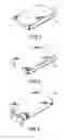
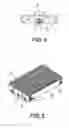
According to the LCD screen using habitually, there are two categories of structures in the lightguide panel. As showing in FIG. 1, 2 and 3 the light source tube B(CCFL) in the structure of the first category is set in one side of the lightguide panel A, and light is in the way of casting from one side of the lightguide panel A(Side Edge Light). FIG. 1 shows the LCD screen lightguide panel A of a notebook computer is wedge-shaped. FIG. 2 shows the LCD screen lightguide panel A of a personal computer is rectangular. Both of lights coming from the side are more reflection rays or refraction rays but fewer direct rays; in addition, they have a fault in moving up and down in the lightguide panel A. The plural of the light source tubes B in the second category are set in the lower edge of the lightguide panel A and more of lights from them transmit directly into the lightguide panel A; thus, there are fewer faults in reflection and refraction.
OBJECTS OF THE INVENTIONThe primary purpose of the present invention is to solve the problem mentioned above in the structure of the lightguide panel using habitually and provide an improved structure of a LCD screen lightguide panel. The method is to set a sunken inlaid groove used for inlaying the light source tube inside in the lower edge of the lightguide panel in order to cooperate with the outer diameter of the light source tube (CCFL), whose lights not only transmit directly into the lightguide panel but also become refraction rays and reflection rays by transmitting from the side to achieve the effect of the highlight flux.
BRIEF DESCRIPTION OF THE DRAWINGFIG. 1 is a perspective view showing the structure of a LCD screen lightguide panel of a notebook computer using habitually.
FIG. 2 is a perspective view showing the structure of a LCD screen lightguide panel of a personal computer using habitually.
FIG. 3 is a perspective view showing the structure of a LCD screen lightguide panel of a personal computer using habitually.
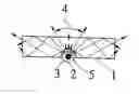
FIG. 4 is a view showing the structure of the lightguide panel in accordance with the present invention.
FIG. 5 is a perspective view showing the light source tube in action in one part of FIG. 4.
DESCRIPTION OF THE REFERRED EMBODIMENTAs showing in FIG. 4 and FIG. 5, the lightguide panel (1) is a wedge-shaped or rectangular light-transmission block and an arc inlaid groove (3) is sunken in the lower edge of the lightguide panel to be in accordance with the outer diameter of the light source tube (2). This inlaid groove (3) can be one or above one arc inlaid grooves (3) that are collimated and separated by suitable distances each other in order to inlay the same amount of the cooperated light source tube (2) and fasten it in position. Lights emitting everywhere from the circumference of the light source tube (2) not only transmit directly into the head (5) of the inlaid groove (3). As showing of the arrows (4), the lights among the ranges all transmit directly and both sides of the head (5) of the inlaid (3) become the way of casting from the side (Side Edge Light) to make light refract or reflect into the lightguide panel (1) that achieves the effect of the highlight flux.
Claims
1. An improved structure of a LCD screen lightguide panel, comprising:
a lightguide panel, formed of a wedge-shaped or rectangular light-transmission block has an arc inlaid groove sunken to be in accordance with the outer diameter of the light source tube in its lower edge;
a light source tube, the outer diameter is in accordance with the arc inlaid groove of said lightguide panel to inlay arc inlaid groove in the lower edge of said lightguide panel and fasten it in position.
2. An improved structure of a LCD screen lightguide panel according to claim 1, wherein the arc inlaid groove sunken in the lower edge of the lightguide panel can be one or more than one.
3. An improved structure of a LCD screen lightguide panel according to claim 2, wherein more than one arc inlaid grooves are installed to be collimated and separated by suitable distances each other.
Images & Drawings included:
Sources:
- United States Patent and Trademark Office - verify current appl. status at the USPTO↗
Recent applications in this class:
- » 20240402409 2024-12-05
RING-SHAPED LIGHT GUIDE MODULE AND LIGHT EMITTING DEVICE - » 20240210609 2024-06-27
LIGHTING FIXTURE WITH WAVEGUIDE - » 20240118476 2024-04-11
Backlight keyswitch and backlight module thereof - » 20240027672 2024-01-25
BACKLIGHT MODULE AND DISPLAY DEVICE - » 20230305212 2023-09-28
Backlight module - » 20230176272 2023-06-08
Light-emitting module and planar light source - » 20230060023 2023-02-23
Light emitting module and planar light source - » 20220252778 2022-08-11
Illumination display panel and method of manufacturing the same - » 20220026620 2022-01-27
Lighting fixture with waveguide - » 20210302644 2021-09-30
Light emitting module