Method for forming inkjet nozzles having a coiled thermal actuator mechanism
US20050145599A1
2005-07-07
11/056,146
2005-02-14
✅ Patent granted
US 7,390,421 B2
2008-06-24
-
-
Anita K Alanko
2025-09-18
Abstract:
A nozzle of an ink jet printer is formed by initially providing a silicon wafer having a circuitry wafer layer including electrical circuitry necessary for the operation of the thermal actuators on demand. The actuator is formed by forming a first inert material layer defining an actuator path in the shape of a planar coil starting at the thermal actuator anchor. Then, a first conductive material layer is formed adjacent the actuator path and attached to the first inert material layer.
Assignee:
- Silverbrook Research Pty Ltd 3,043 🇦🇺 Balmain, New South Wales, Australia
Interested in similar patents?
Get notified when new applications in this technology area are published.
Classification:
H04N5/2628 » CPC main
Details of television systems; Studio circuitry; Studio devices; Studio equipment ; Cameras comprising an electronic image sensor, e.g. digital cameras, video cameras, TV cameras, video cameras, camcorders, webcams, camera modules for embedding in other devices, e.g. mobile phones, computers or vehicles; Studio circuits, e.g. for mixing, switching-over, change of character of image, other special effects ; Cameras specially adapted for the electronic generation of special effects Alteration of picture size, shape, position or orientation, e.g. zooming, rotation, rolling, perspective, translation
B41J2/14427 » CPC further
Typewriters or selective printing mechanisms characterised by the printing or marking process for which they are designed characterised by bringing liquid or particles selectively into contact with a printing material; Ink jet; Nozzles; Structure thereof only for on-demand ink jet heads Structure of ink jet print heads with thermal bend detached actuators
B41J2/1623 » CPC further
Typewriters or selective printing mechanisms characterised by the printing or marking process for which they are designed characterised by bringing liquid or particles selectively into contact with a printing material; Ink jet; Nozzles; Production of nozzles manufacturing processes bonding and adhesion
B41J2/1626 » CPC further
Typewriters or selective printing mechanisms characterised by the printing or marking process for which they are designed characterised by bringing liquid or particles selectively into contact with a printing material; Ink jet; Nozzles; Production of nozzles manufacturing processes etching
B41J2/1631 » CPC further
Typewriters or selective printing mechanisms characterised by the printing or marking process for which they are designed characterised by bringing liquid or particles selectively into contact with a printing material; Ink jet; Nozzles; Production of nozzles manufacturing processes photolithography
B41J2/1632 » CPC further
Typewriters or selective printing mechanisms characterised by the printing or marking process for which they are designed characterised by bringing liquid or particles selectively into contact with a printing material; Ink jet; Nozzles; Production of nozzles manufacturing processes machining
B41J2/1635 » CPC further
Typewriters or selective printing mechanisms characterised by the printing or marking process for which they are designed characterised by bringing liquid or particles selectively into contact with a printing material; Ink jet; Nozzles; Production of nozzles manufacturing processes dividing the wafer into individual chips
B41J2/1637 » CPC further
Typewriters or selective printing mechanisms characterised by the printing or marking process for which they are designed characterised by bringing liquid or particles selectively into contact with a printing material; Ink jet; Nozzles; Production of nozzles manufacturing processes molding
B41J2/1648 » CPC further
Typewriters or selective printing mechanisms characterised by the printing or marking process for which they are designed characterised by bringing liquid or particles selectively into contact with a printing material; Ink jet; Nozzles; Production of nozzles Production of print heads with thermal bend detached actuators
B41J2/17503 » CPC further
Typewriters or selective printing mechanisms characterised by the printing or marking process for which they are designed characterised by bringing liquid or particles selectively into contact with a printing material; Ink jet characterised by ink handling; Ink supply systems ; Circuit parts therefor Ink cartridges
B41J2/17513 » CPC further
Typewriters or selective printing mechanisms characterised by the printing or marking process for which they are designed characterised by bringing liquid or particles selectively into contact with a printing material; Ink jet characterised by ink handling; Ink supply systems ; Circuit parts therefor; Ink cartridges Inner structure
B41J2/17596 » CPC further
Typewriters or selective printing mechanisms characterised by the printing or marking process for which they are designed characterised by bringing liquid or particles selectively into contact with a printing material; Ink jet characterised by ink handling; Ink supply systems ; Circuit parts therefor Ink pumps, ink valves
B82Y30/00 » CPC further
Nanotechnology for materials or surface science, e.g. nanocomposites
G06F21/79 » CPC further
Security arrangements for protecting computers, components thereof, programs or data against unauthorised activity; Protecting specific internal or peripheral components, in which the protection of a component leads to protection of the entire computer to assure secure storage of data in semiconductor storage media, e.g. directly-addressable memories
G06F21/86 » CPC further
Security arrangements for protecting computers, components thereof, programs or data against unauthorised activity; Protecting specific internal or peripheral components, in which the protection of a component leads to protection of the entire computer Secure or tamper-resistant housings
G06K1/121 » CPC further
Methods or arrangements for marking the record carrier in digital fashion otherwise than by punching by printing code marks
G06K7/14 » CPC further
Methods or arrangements for sensing record carriers, e.g. for reading patterns by electromagnetic radiation, e.g. optical sensing; by corpuscular radiation using light without selection of wavelength, e.g. sensing reflected white light
G06K7/1417 » CPC further
Methods or arrangements for sensing record carriers, e.g. for reading patterns by electromagnetic radiation, e.g. optical sensing; by corpuscular radiation using light without selection of wavelength, e.g. sensing reflected white light; Methods for optical code recognition the method being specifically adapted for the type of code 2D bar codes
G06K19/06037 » CPC further
Record carriers for use with machines and with at least a part designed to carry digital markings characterised by the kind of the digital marking, e.g. shape, nature, code with optically detectable marking multi-dimensional coding
G06K19/073 » CPC further
Record carriers for use with machines and with at least a part designed to carry digital markings characterised by the kind of the digital marking, e.g. shape, nature, code; Record carriers with conductive marks, printed circuits or semiconductor circuit elements, e.g. credit or identity cards also with resonating or responding marks without active components with integrated circuit chips Special arrangements for circuits, e.g. for protecting identification code in memory
G11C11/56 » CPC further
Digital stores characterised by the use of particular electric or magnetic storage elements; Storage elements therefor using storage elements with more than two stable states represented by steps, e.g. of voltage, current, phase, frequency
H04N5/225 » CPC further
Details of television systems; Studio circuitry; Studio devices; Studio equipment ; Cameras comprising an electronic image sensor, e.g. digital cameras, video cameras, TV cameras, video cameras, camcorders, webcams, camera modules for embedding in other devices, e.g. mobile phones, computers or vehicles Television cameras ; Cameras comprising an electronic image sensor, e.g. digital cameras, video cameras, camcorders, webcams, camera modules specially adapted for being embedded in other devices, e.g. mobile phones, computers or vehicles
B41J2/16585 » CPC further
Typewriters or selective printing mechanisms characterised by the printing or marking process for which they are designed characterised by bringing liquid or particles selectively into contact with a printing material; Ink jet; Nozzles; Preventing or detecting of nozzle clogging, e.g. cleaning, capping or moistening for nozzles for paper-width or non-reciprocating print heads
B41J2002/041 » CPC further
Typewriters or selective printing mechanisms characterised by the printing or marking process for which they are designed characterised by bringing liquid or particles selectively into contact with a printing material; Ink jet characterised by the jet generation process generating single droplets or particles on demand Electromagnetic transducer
B41J2202/21 » CPC further
Embodiments of or processes related to ink-jet or thermal heads; Embodiments of or processes related to ink-jet heads Line printing
G06F2221/2129 » CPC further
Indexing scheme relating to security arrangements for protecting computers, components thereof, programs or data against unauthorised activity; Indexing scheme relating to and subgroups addressing additional information or applications relating to security arrangements for protecting computers, components thereof, programs or data against unauthorised activity Authenticate client device independently of the user
B41J2/16 IPC
Typewriters or selective printing mechanisms characterised by the printing or marking process for which they are designed characterised by bringing liquid or particles selectively into contact with a printing material; Ink jet; Nozzles Production of nozzles
Description
CROSS REFERENCE TO RELATED APPLICATIONThe present application is a continuation of U.S. application Ser. No. 09/113,076 filed Jul. 10, 1998, the entire contents of which are herein incorporated by reference.
CROSS REFERENCES TO RELATED APPLICATIONSThe following Australian provisional patent applications are hereby incorporated by cross-reference. For the purposes of location and identification, U.S. patent applications identified by their U.S. patent application serial numbers (USSN) are listed alongside the Australian applications from which the U.S. patent applications claim the right of priority.
| US PATENT/PATENT | ||
| CROSS-REFERENCED | APPLICATION (CLAIMING | |
| AUSTRALIAN PRO- | RIGHT OF PRIORITY | |
| VISIONAL PATENT | FROM AUSTRALIAN PRO- | DOCKET |
| APPLICATION NO. | VISIONAL APPLICATION) | NO. |
| PO7991 | 09/113,060 | ART01 |
| PO8505 | 09/113,070 | ART02 |
| PO7988 | 09/113,073 | ART03 |
| PO9395 | 09/112,748 | ART04 |
| PO8017 | 09/112,747 | ART06 |
| PO8014 | 09/112,776 | ART07 |
| PO8025 | 09/112,750 | ART08 |
| PO8032 | 09/112,746 | ART09 |
| PO7999 | 09/112,743 | ART10 |
| PO7998 | 09/112,742 | ART11 |
| PO8031 | 09/112,741 | ART12 |
| PO8030 | 09/112,740 | ART13 |
| PO7997 | 09/112,739 | ART15 |
| PO7979 | 09/113,053 | ART16 |
| PO8015 | 09/112,738 | ART17 |
| PO7978 | 09/113,067 | ART18 |
| PO7982 | 09/113,063 | ART19 |
| PO7989 | 09/113,069 | ART20 |
| PO8019 | 09/112,744 | ART21 |
| PO7980 | 09/113,058 | ART22 |
| PO8018 | 09/112,777 | ART24 |
| PO7938 | 09/113,224 | ART25 |
| PO8016 | 09/112,804 | ART26 |
| PO8024 | 09/112,805 | ART27 |
| PO7940 | 09/113,072 | ART28 |
| PO7939 | 09/112,785 | ART29 |
| PO8501 | 09/112,797 | ART30 |
| PO8500 | 09/112,796 | ART31 |
| PO7987 | 09/113,071 | ART32 |
| PO8022 | 09/112,824 | ART33 |
| PO8497 | 09/113,090 | ART34 |
| PO8020 | 09/112,823 | ART38 |
| PO8023 | 09/113,222 | ART39 |
| PO8504 | 09/112,786 | ART42 |
| PO8000 | 09/113,051 | ART43 |
| PO7977 | 09/112,782 | ART44 |
| PO7934 | 09/113,056 | ART45 |
| PO7990 | 09/113,059 | ART46 |
| PO8499 | 09/113,091 | ART47 |
| PO8502 | 09/112,753 | ART48 |
| PO7981 | 09/113,055 | ART50 |
| PO7986 | 09/113,057 | ART51 |
| PO7983 | 09/113,054 | ART52 |
| PO8026 | 09/112,752 | ART53 |
| PO8027 | 09/112,759 | ART54 |
| PO8028 | 09/112,757 | ART56 |
| PO9394 | 09/112,758 | ART57 |
| PO9396 | 09/113,107 | ART58 |
| PO9397 | 09/112,829 | ART59 |
| PO9398 | 09/112,792 | ART60 |
| PO9399 | 6,106,147 | ART61 |
| PO9400 | 09/112,790 | ART62 |
| PO9401 | 09/112,789 | ART63 |
| PO9402 | 09/112,788 | ART64 |
| PO9403 | 09/112,795 | ART65 |
| PO9405 | 09/112,749 | ART66 |
| PP0959 | 09/112,784 | ART68 |
| PP1397 | 09/112,783 | ART69 |
| PP2370 | 09/112,781 | DOT01 |
| PP2371 | 09/113,052 | DOT02 |
| PO8003 | 09/112,834 | Fluid01 |
| PO8005 | 09/113,103 | Fluid02 |
| PO9404 | 09/113,101 | Fluid03 |
| PO8066 | 09/112,751 | IJ01 |
| PO8072 | 09/112,787 | IJ02 |
| PO8040 | 09/112,802 | IJ03 |
| PO8071 | 09/112,803 | IJ04 |
| PO8047 | 09/113,097 | IJ05 |
| PO8035 | 09/113,099 | IJ06 |
| PO8044 | 09/113,084 | IJ07 |
| PO8063 | 09/113,066 | IJ08 |
| PO8057 | 09/112,778 | IJ09 |
| PO8056 | 09/112,779 | IJ10 |
| PO8069 | 09/113,077 | IJ11 |
| PO8049 | 09/113,061 | IJ12 |
| PO8036 | 09/112,818 | IJ13 |
| PO8048 | 09/112,816 | IJ14 |
| PO8070 | 09/112,772 | IJ15 |
| PO8067 | 09/112,819 | IJ16 |
| PO8001 | 09/112,815 | IJ17 |
| PO8038 | 09/113,096 | IJ18 |
| PO8033 | 09/113,068 | IJ19 |
| PO8002 | 09/113,095 | IJ20 |
| PO8068 | 09/112,808 | IJ21 |
| PO8062 | 09/112,809 | IJ22 |
| PO8034 | 09/112,780 | IJ23 |
| PO8039 | 09/113,083 | IJ24 |
| PO8041 | 09/113,121 | IJ25 |
| PO8004 | 09/113,122 | IJ26 |
| PO8037 | 09/112,793 | IJ27 |
| PO8043 | 09/112,794 | IJ28 |
| PO8042 | 09/113,128 | IJ29 |
| PO8064 | 09/113,127 | IJ30 |
| PO9389 | 09/112,756 | IJ31 |
| PO9391 | 09/112,755 | IJ32 |
| PP0888 | 09/112,754 | IJ33 |
| PP0891 | 09/112,811 | IJ34 |
| PP0890 | 09/112,812 | IJ35 |
| PP0873 | 09/112,813 | IJ36 |
| PP0993 | 09/112,814 | IJ37 |
| PP0890 | 09/112,764 | IJ38 |
| PP1398 | 09/112,765 | IJ39 |
| PP2592 | 09/112,767 | IJ40 |
| PP2593 | 09/112,768 | IJ41 |
| PP3991 | 09/112,807 | IJ42 |
| PP3987 | 09/112,806 | IJ43 |
| PP3985 | 09/112,820 | IJ44 |
| PP3983 | 09/112,821 | IJ45 |
| PO7935 | 09/112,822 | IJM01 |
| PO7936 | 09/112,825 | IJM02 |
| PO7937 | 09/112,826 | IJM03 |
| PO8061 | 09/112,827 | IJM04 |
| PO8054 | 09/112,828 | IJM05 |
| PO8065 | 6,071,750 | IJM06 |
| PO8055 | 09/113,108 | IJM07 |
| PO8053 | 09/113,109 | IJM08 |
| PO8078 | 09/113,123 | IJM09 |
| PO7933 | 09/113,114 | IJM10 |
| PO7950 | 09/113,115 | IJM11 |
| PO7949 | 09/113,129 | IJM12 |
| PO8060 | 09/113,124 | IJM13 |
| PO8059 | 09/113,125 | IJM14 |
| PO8073 | 09/113,126 | IJM15 |
| PO8076 | 09/113,119 | IJM16 |
| PO8075 | 09/113,120 | IJM17 |
| PO8079 | 09/113,221 | IJM18 |
| PO8050 | 09/113,116 | IJM19 |
| PO8052 | 09/113,118 | IJM20 |
| PO7948 | 09/113,117 | IJM21 |
| PO7951 | 09/113,113 | IJM22 |
| PO8074 | 09/113,130 | IJM23 |
| PO7941 | 09/113,110 | IJM24 |
| PO8077 | 09/113,112 | IJM25 |
| PO8058 | 09/113,087 | IJM26 |
| PO8051 | 09/113,074 | IJM27 |
| PO8045 | 6,110,754 | IJM28 |
| PO7952 | 09/113,088 | IJM29 |
| PO8046 | 09/112,771 | IJM30 |
| PO9390 | 09/112,769 | IJM31 |
| PO9392 | 09/112,770 | IJM32 |
| PP0889 | 09/112,798 | IJM35 |
| PP0887 | 09/112,801 | IJM36 |
| PP0882 | 09/112,800 | IJM37 |
| PP0874 | 09/112,799 | IJM38 |
| PP1396 | 09/113,098 | IJM39 |
| PP3989 | 09/112,833 | IJM40 |
| PP2591 | 09/112,832 | IJM41 |
| PP3990 | 09/112,831 | IJM42 |
| PP3986 | 09/112,830 | IJM43 |
| PP3984 | 09/112,836 | IJM44 |
| PP3982 | 09/112,835 | IJM45 |
| PP0895 | 09/113,102 | IR01 |
| PP0870 | 09/113,106 | IR02 |
| PP0869 | 09/113,105 | IR04 |
| PP0887 | 09/113,104 | IR05 |
| PP0885 | 09/112,810 | IR06 |
| PP0884 | 09/112,766 | IR10 |
| PP0886 | 09/113,085 | IR12 |
| PP0871 | 09/113,086 | IR13 |
| PP0876 | 09/113,094 | IR14 |
| PP0877 | 09/112,760 | IR16 |
| PP0878 | 09/112,773 | IR17 |
| PP0879 | 09/112,774 | IR18 |
| PP0883 | 09/112,775 | IR19 |
| PP0880 | 6,152,619 | IR20 |
| PP0881 | 09/113,092 | IR21 |
| PO8006 | 6,087,638 | MEMS02 |
| PO8007 | 09/113,093 | MEMS03 |
| PO8008 | 09/113,062 | MEMS04 |
| PO8010 | 6,041,600 | MEMS05 |
| PO8011 | 09/113,082 | MEMS06 |
| PO7947 | 6,067,797 | MEMS07 |
| PO7944 | 09/113,080 | MEMS09 |
| PO7946 | 6,044,646 | MEMS10 |
| PO9393 | 09/113,065 | MEMS11 |
| PP0875 | 09/113,078 | MEMS12 |
| PP0894 | 09/113,075 | MEMS13 |
Not applicable.
FIELD OF THE INVENTIONThe present invention relates to the field of inkjet printing and, in particular, discloses a method of manufacture of an ink jet printer having a thermal actuator comprising an external coil spring.
BACKGROUND OF THE INVENTIONMany ink jet printing mechanisms are known. Unfortunately, in mass production techniques, the production of ink jet heads is quite difficult. For example, often, the orifice or nozzle plate is constructed separately from the ink supply and ink ejection mechanism and bonded to the mechanism at a later stage (Hewlett-Packard Journal, Vol. 36 no 5, pp 33-37 (1985)). These separate material processing steps required in handling such precision devices often add a substantial expense in manufacturing.
Additionally, side shooting ink jet technologies (U.S. Pat. No. 4,899,181) are often used but again, this limits the amount of mass production throughput given any particular capital investment.
Additionally, more esoteric techniques are also often utilised. These can include electroforming of nickel stage (Hewlett-Packard Journal, Vol. 36 no 5, pp 33-37 (1985)), electro-discharge machining, laser ablation (U.S. Pat. No. 5,208,604), micro-punching, etc.
The utilisation of the above techniques is likely to add substantial expense to the mass production of ink jet print heads and therefore add substantially to their final cost.
It would therefore be desirable if an efficient system for the mass production of ink jet print heads could be developed.
SUMMARY OF THE INVENTIONIt is an object of the present invention to provide for a method of manufacture of an ink jet printer having a thermal actuator comprising an external coil spring.
In accordance with a first aspect of the present invention, there is provided a method of manufacture of an ink jet printer having a thermal actuator comprising an external coil spring wherein an array of nozzles are formed on a substrate utilising planar monolithic deposition, lithographic and etching processes.
Multiple ink jet heads are preferably formed simultaneously on a single planar substrate which can comprise a silicon wafer.
The print heads are preferably formed utilising standard vlsi/ulsi processing with integrated drive electronics are preferably formed on the same substrate. The integrated drive electronics may be formed utilising a CMOS fabrication process.
Ink can be ejected from the substrate substantially normal to the substrate.
In accordance with a further aspect of the present invention, there is provided a method of manufacture of a thermally actuated ink jet printer comprising a series of nozzle chambers which ejects ink via the utilization of a thermal actuator device, comprising the steps of: (a) initially providing a silicon wafer having a circuitry wafer layer including the electrical circuitry necessary for the operation of the thermal actuators on demand; (b) etching an ink inlet aperture in the circuitry wafer layer; (c) depositing and etching a first sacrificial layer on top of the silicon and circuitry wafer layer and etching the first sacrificial layer in an area defining a first portion of a nozzle chamber wall, a thermal actuator anchor and a thermal actuator end point; (d) depositing and etching a first inert material layer in defining a first actuator path starting at the thermal actuator anchor; (e) depositing and etching a first conductive material layer adjacent the first actuator path and attached to the first inert material layer; (f) depositing and etching a non-conductive layer over the first conductive material layer, the etching including etching predetermined vias for interconnection of the first conductive material layer with a second conductive material layer; (g) depositing and etching a second inert material layer on top of the first inert material layer; (h) depositing and etching a second conductive material layer on top of the non-conductive layer having a conductive interconnect to the first conductive material layer; (i) depositing and etching a series of inert material layers and sacrificial layers to form a nozzle chamber including an ink ejection hole and a nozzle chamber paddle attached to one of the inert material layers or the conductive layers at the thermal actuator end point; (j) etching an ink supply channel through the wafer to the nozzle chamber; and (k) etching away the sacrificial layers.
The conductive material layers are preferably formed from a material having a high Young's modulus such as titanium nitride. The first and second inert material layers can comprise substantially glass. The first actuator path can comprise substantially a coil.
The steps are preferably also utilized to simultaneously separate the wafer into separate printheads.
BRIEF DESCRIPTION OF THE DRAWINGSNotwithstanding any other forms which may fall within the scope of the present invention, preferred forms of the invention will now be described, by way of example only, with reference to the accompanying drawings in which:
FIG. 1 illustrates a single ink ejection mechanism as constructed in accordance with the principles of the preferred embodiment;
FIG. 2 is a section through the line II-II of the actuator arm of FIG. 1;
FIGS. 3-5 illustrate the basic operation of the ink ejection mechanism of the preferred embodiment;
FIG. 6 is an exploded perspective view of an ink ejection mechanism.
FIG. 7 provides a legend of the materials indicated in FIGS. 8 to 22; and
FIG. 8 to FIG. 22 illustrate sectional views of the manufacturing steps in one form of construction of an ink jet printhead nozzle.
DESCRIPTION OF PREFERRED AND OTHER EMBODIMENTSIn the preferred embodiment, there is provided an inkjet printer having a series of ink ejection mechanisms wherein each ink ejection mechanism includes a paddle actuated by a coil actuator, the coil spring actuator having a unique cross section so as to provide for efficient actuation as a coiled thermal actuator.
Turning initially to FIG. 1, there is illustrated a single ink ejection mechanism 1 constructed in accordance with the principles of the preferred embodiment. The ink ejection mechanism 1 includes a chamber 2 having a rim 3. The chamber 2 is normally filled with ink which bulges out around a surface having a border along the edge of rim 3, the ink being retained within the chamber 2 by means of surface tension around the rim 3. Outside of the chamber 2 is located a thermal actuator device 5. The thermal actuator device 5 is interconnected via a strut 6 through a hole 7 to a paddle device within the chamber 2. The strut 6 and hole 7 are treated so as to be hydrophobic. Further, the hole 7 is provided in a thin elongated form so that surface tension characteristics also assist in stopping any ink from flowing out of the hole 7.
The thermal actuator device 5 comprises a first arm portion 9 which can be constructed from glass or other suitable material. A second arm portion 10 can be constructed from material such as titanium diboride which has a large Young's modulus or bending strength and hence, when a current is passed through the titanium diboride layer 10, it expands with a predetermined coefficient of thermal expansion. The thin strip 10 has a high Young's modulus or bending strength and therefore the thin strip 10 is able to bend the much thicker strip 9 which has a substantially lower Young's modulus.
Turning to FIG. 2, there is illustrated a cross-section of the arm through the line II-II of FIG. 1 illustrating the structure of the actuator device 5. As described previously, the actuator device 5 includes two titanium diboride portions 10a, 10b forming a circuit around the coil in addition to the glass portion 9 which also provides for electrical isolation of the two arms, the arms being conductively joined at the strut end.
Turning now to FIGS. 3-5, there will now be explaining the operation of the ink ejection mechanism 1 for the ejection of ink. Initially, before the paddle 8 has started moving, the situation is as illustrated in FIG. 3 with the nozzle chamber 2 being filled with ink and having a slightly bulging meniscus 12. Upon actuation of the actuator mechanism, the paddle 8 begins to move towards the nozzle rim 3 resulting in a substantial increase in pressure in the area around the nozzle rim 3. This in turn results in the situation as illustrated in FIG. 4 wherein the meniscus begins to significantly bulge as a result of the increases in pressure. Subsequently, the actuator is deactivated resulting in a general urge for the paddle 8 to return to its rest position. This results in the ink being sucked back into the chamber 2 which in turn results in the meniscus necking and breaking off into a meniscus 12 and ink drop 14, the drop 14 proceeding to a paper or film medium (not shown) for marking. The meniscus 12 has generally a concave shape and surface tension characteristics result in chamber refilling by means of in flow 13 from an ink supply channel etched through the wafer. The refilling is as a consequence of surface tension forces on the meniscus 12. Eventually the meniscus returns to its quiescent state as illustrated in FIG. 3.
Turning now to FIG. 6, there is illustrated an exploded perspective view of a single ink ejection mechanism 1 illustrating the various material layers. The ink ejection mechanism 1 can be formed as part of a large array of mechanisms forming a print head with multiple print heads being simultaneously formed on a silicon wafer 17. The wafer 17 is initially processed so as to incorporate a standard CMOS circuitry layer 18 which provides for the electrical interconnect for the control of the conductive portions of the actuator. The CMOS layer 18 can be completed with a silicon nitride passivation layer so as to protect it from subsequent processing steps in addition to ink flows through channel 20. The subsequent layers eg. 9, 10 and 2 can be deposited utilising standard micro-electro mechanical systems (MEMS) construction techniques including the deposit of sacrificial aluminum layers in addition to the deposit of the layers 10 constructed from titanium diboride the layer 9 constructed from glass material and the nozzle chamber proper 2 again constructed from titanium diboride. Each of these layers can be built up in a sacrificial material such as aluminum which is subsequently etched away. Further, an ink supply channel eg. 21 can be etched through the wafer 17. The etching can be by means of an isotropic crystallographic silicon etch or an isotropic dry etch. A dry etch system capable of high aspect ratio silicon trench etching such as the Surface Technology Systems (STS) Advance Silicon Etch (ASE) system is recommended.
Subsequent to construction of the nozzle arrangement 1, it can be attached to an ink supply apparatus for supplying ink to the reverse surface of the wafer 17 so that ink can flow into chamber 2.
The external surface of nozzle chamber 2 including rim 3, in addition to the area surrounding slot 7, can then be hydrophobically treated so as to reduce the possibility of any ink exiting slot 7.
One form of detailed manufacturing process which can be used to fabricate monolithic ink jet print heads operating in accordance with the principles taught by the present embodiment can proceed utilizing the following steps:
1. Using a double sided polished wafer 17, Complete drive transistors, data distribution, and timing circuits using a 0.5 micron, one poly, 2 metal CMOS process to form layer 18. This step is shown in FIG. 8. For clarity, these diagrams may not be to scale, and may not represent a cross section though any single plane of the nozzle. FIG. 7 is a key to representations of various materials in these manufacturing diagrams, and those of other cross referenced ink jet configurations.
2. Etch oxide layer 18 down to silicon or aluminum using Mask 1. This mask defines the ink inlet, the heater contact vias, and the edges of the print heads chip. This step is shown in FIG. 9.
3. Deposit 1 micron of sacrificial material 30 (e.g. aluminum).
4. Etch the sacrificial layer 30 using Mask 2, defining the nozzle chamber wall and the actuator anchor point. This step is shown in FIG. 10.
5. Deposit 1 micron of glass 31.
6. Etch the glass 31 using Mask 3, which defines the lower layer of the actuator loop.
7. Deposit 1 micron of heater material 32, for example titanium nitride (TiN) or titanium diboride (TiB2). Planarize using CMP. Steps 5 to 7 form a ‘damascene’ process. This step is shown in FIG. 11.
8. Deposit 0.1 micron of silicon nitride (not shown).
9. Deposit 1 micron of glass 33.
10. Etch the glass 33 using Mask 4, which defines the upper layer of the actuator loop.
11. Etch the silicon nitride using Mask 5, which defines the vias connecting the upper layer of the actuator loop to the lower layer of the actuator loop.
12. Deposit 1 micron of the same heater material 34 as in step 7 heater material 32. Planarize using CMP. Steps 8 to 12 form a ‘dual damascene’ process. This step is shown in FIG. 12.
13. Etch the glass down to the sacrificial layer 30 using Mask 6, which defines the actuator and the nozzle chamber wall, with the exception of the nozzle chamber actuator slot. This step is shown in FIG. 13.
14. Wafer probe. All electrical connections are complete at this point, bond pads are accessible, and the chips are not yet separated.
15. Deposit 3 microns of sacrificial material 35.
16. Etch the sacrificial layer 35 down to glass using Mask 7, which defines the nozzle chamber wall, with the exception of the nozzle chamber actuator slot. This step is shown in FIG. 14.
17. Deposit 1 micron of PECVD glass 36 and planarize down to the sacrificial layer 35 using CMP. This step is shown in FIG. 15.
18. Deposit 5 microns of sacrificial material 37.
19. Etch the sacrificial material 37 down to glass using Mask 8. This mask defines the nozzle chamber wall and the paddle. This step is shown in FIG. 16.
20. Deposit 3 microns of PECVD glass 38 and planarize down to the sacrificial layer 37 using CMP.
21. Deposit 1 micron of sacrificial material 39.
22. Etch the sacrificial material 39 down to glass using Mask 9. This mask defines the nozzle chamber wall. This step is shown in FIG. 17.
23. Deposit 3 microns of PECVD glass 40.
24. Etch to a depth of (approx.) 1 micron using Mask 10. This mask defines the nozzle rim 3. This step is shown in FIG. 18.
25. Etch down to the sacrificial layer 39 using Mask 11. This mask defines the roof of the nozzle chamber, and the nozzle itself. This step is shown in FIG. 19.
26. Back-etch completely through the silicon wafer (with, for example, an ASE Advanced Silicon Etcher from Surface Technology Systems) using Mask 12. This mask defines the ink inlets 21 which are etched through the wafer. The wafer is also diced by this etch. This step is shown in FIG. 20.
27. Etch the sacrificial material 30, 35, 37, 39. The nozzle chambers are cleared, the actuators freed, and the chips are separated by this etch. This step is shown in FIG. 21.
28. Mount the print heads in their packaging, which may be a molded plastic former incorporating ink channels which supply the appropriate color ink to the ink inlets at the back of the wafer.
29. Connect the print heads to their interconnect systems. For a low profile connection with minimum disruption of airflow, TAB may be used. Wire bonding may also be used if the printer is to be operated with sufficient clearance to the paper.
30. Hydrophobize the front surface of the print heads.
31. Fill the completed print heads with ink 41 and test them. A filled nozzle is shown in FIG. 22.
The presently disclosed ink jet printing technology is potentially suited to a wide range of printing system including: color and monochrome office printers, short run digital printers, high speed digital printers, offset press supplemental printers, low cost scanning printers high speed pagewidth printers, notebook computers with in-built pagewidth printers, portable color and monochrome printers, color and monochrome copiers, color and monochrome facsimile machines, combined printer, facsimile and copying machines, label printers, large format plotters, photograph copiers, printers for digital photographic “minilabs”, video printers, PHOTO CD (PHOTO CD is a registered trade mark of the Eastman Kodak Company) printers, portable printers for PDAs, wallpaper printers, indoor sign printers, billboard printers, fabric printers, camera printers and fault tolerant commercial printer arrays.
It would be appreciated by a person skilled in the art that numerous variations and/or modifications may be made to the present invention as shown in the specific embodiments without departing from the spirit or scope of the invention as broadly described. The present embodiments are, therefore, to be considered in all respects to be illustrative and not restrictive.
Ink Jet Technologies
The embodiments of the invention use an ink jet printer type device. Of course many different devices could be used. However presently popular ink jet printing technologies are unlikely to be suitable.
The most significant problem with thermal ink jet is power consumption. This is approximately 100 times that required for high speed, and stems from the energy-inefficient means of drop ejection. This involves the rapid boiling of water to produce a vapor bubble which expels the ink. Water has a very high heat capacity, and must be superheated in thermal ink jet applications. This leads to an efficiency of around 0.02%, from electricity input to drop momentum (and increased surface area) out.
The most significant problem with piezoelectric ink jet is size and cost. Piezoelectric crystals have a very small deflection at reasonable drive voltages, and therefore require a large area for each nozzle. Also, each piezoelectric actuator must be connected to its drive circuit on a separate substrate. This is not a significant problem at the current limit of around 300 nozzles per print head, but is a major impediment to the fabrication of pagewidth print heads with 19,200 nozzles.
Ideally, the ink jet technologies used meet the stringent requirements of in-camera digital color printing and other high quality, high speed, low cost printing applications. To meet the requirements of digital photography, new ink jet technologies have been created. The target features include:
-
- low power (less than 10 Watts)
- high resolution capability (1,600 dpi or more)
- photographic quality output
- low manufacturing cost
- small size (pagewidth times minimum cross section)
- high speed (<2 seconds per page).
All of these features can be met or exceeded by the ink jet systems described below with differing levels of difficulty. Forty-five different ink jet technologies have been developed by the Assignee to give a wide range of choices for high volume manufacture. These technologies form part of separate applications assigned to the present Assignee as set out in the table above under the heading Cross References to Related Applications.
The ink jet designs shown here are suitable for a wide range of digital printing systems, from battery powered one-time use digital cameras, through to desktop and network printers, and through to commercial printing systems For ease of manufacture using standard process equipment, the print head is designed to be a monolithic 0.5 micron CMOS chip with MEMS post processing. For color photographic applications, the print head is 100 mm long, with a width which depends upon the ink jet type. The smallest print head designed is IJ38, which is 0.35 mm wide, giving a chip area of 35 square mm. The print heads each contain 19,200 nozzles plus data and control circuitry.
Ink is supplied to the back of the print head by injection molded plastic ink channels. The molding requires 50 micron features, which can be created using a lithographically micromachined insert in a standard injection molding tool. Ink flows through holes etched through the wafer to the nozzle chambers fabricated on the front surface of the wafer. The print head is connected to the camera circuitry by tape automated bonding.
Tables of Drop-on-Demand Ink Jets
Eleven important characteristics of the fundamental operation of individual ink jet nozzles have been identified. These characteristics are largely orthogonal, and so can be elucidated as an eleven dimensional matrix. Most of the eleven axes of this matrix include entries developed by the present assignee.
The following tables form the axes of an eleven dimensional table of ink jet types.
-
- Actuator mechanism (18 types)
- Basic operation mode (7 types)
- Auxiliary mechanism (8 types)
- Actuator amplification or modification method (17 types)
- Actuator motion (19 types)
- Nozzle refill method (4 types)
- Method of restricting back-flow through inlet (10 types)
- Nozzle clearing method (9 types)
- Nozzle plate construction (9 types)
- Drop ejection direction (5 types)
- Ink type (7 types)
The complete eleven dimensional table represented by these axes contains 36.9 billion possible configurations of ink jet nozzle. While not all of the possible combinations result in a viable ink jet technology, many million configurations are viable. It is clearly impractical to elucidate all of the possible configurations. Instead, certain ink jet types have been investigated in detail. These are designated IJ01 to IJ45 which matches the docket numbers in the in the table under the heading Cross References to Related Applications.
Other ink jet configurations can readily be derived from these forty-five examples by substituting alternative configurations along one or more of the 111 axes. Most of the IJ01 to IJ45 examples can be made into ink jet print heads with characteristics superior to any currently available ink jet technology.
Where there are prior art examples known to the inventor, one or more of these examples are listed in the examples column of the tables below. The IJ01 to IJ45 series are also listed in the examples column. In some cases, a printer may be listed more than once in a table, where it shares characteristics with more than one entry.
Suitable applications for the ink jet technologies include: Home printers, Office network printers, Short run digital printers, Commercial print systems, Fabric printers, Pocket printers, Internet WWW printers, Video printers, Medical imaging, Wide format printers, Notebook PC printers, Fax machines, Industrial printing systems, Photocopiers, Photographic minilabs etc.
The information associated with the aforementioned 11 dimensional matrix are set out in the following tables.
| ACTUATOR MECHANISM (APPLIED ONLY TO SELECTED INK DROPS) |
| Description | Advantages | Disadvantages | Examples | |
| Thermal | An electrothermal | Large force | High power | Canon Bubblejet |
| bubble | heater heats the ink to | generated | Ink carrier | 1979 Endo et al GB |
| above boiling point, | Simple | limited to water | patent 2,007,162 | |
| transferring significant | construction | Low efficiency | Xerox heater-in- | |
| heat to the aqueous | No moving parts | High | pit 1990 Hawkins et | |
| ink. A bubble | Fast operation | temperatures | al U.S. Pat. No. | |
| nucleates and quickly | Small chip area | required | 4,899,181 | |
| forms, expelling the | required for actuator | High mechanical | Hewlett-Packard | |
| ink. | stress | TIJ 1982 Vaught et | ||
| The efficiency of the | Unusual | al U.S. Pat. No. | ||
| process is low, with | materials required | 4,490,728 | ||
| typically less than | Large drive | |||
| 0.05% of the electrical | transistors | |||
| energy being | Cavitation causes | |||
| transformed into | actuator failure | |||
| kinetic energy of the | Kogation reduces | |||
| drop. | bubble formation | |||
| Large print heads | ||||
| are difficult to | ||||
| fabricate | ||||
| Piezo- | A piezoelectric crystal | Low power | Very large area | Kyser et al |
| electric | such as lead | consumption | required for actuator | U.S. Pat. No. 3,946,398 |
| lanthanum zirconate | Many ink types | Difficult to | Zoltan U.S. Pat. | |
| (PZT) is electrically | can be used | integrate with | No. 3,683,212 | |
| activated, and either | Fast operation | electronics | 1973 Stemme | |
| expands, shears, or | High efficiency | High voltage | U.S. Pat. No. 3,747,120 | |
| bends to apply | drive transistors | Epson Stylus | ||
| pressure to the ink, | required | Tektronix | ||
| ejecting drops. | Full pagewidth | IJ04 | ||
| print heads | ||||
| impractical due to | ||||
| actuator size | ||||
| Requires | ||||
| electrical poling in | ||||
| high field strengths | ||||
| during manufacture | ||||
| Electro- | An electric field is | Low power | Low maximum | Seiko Epson, |
| strictive | used to activate | consumption | strain (approx. | Usui et all JP |
| electrostriction in | Many ink types | 0.01%) | 253401/96 | |
| relaxor materials such | can be used | Large area | IJ04 | |
| as lead lanthanum | Low thermal | required for actuator | ||
| zirconate titanate | expansion | due to low strain | ||
| (PLZT) or lead | Electric field | Response speed | ||
| magnesium niobate | strength required | is marginal | ||
| (PMN). | (approx. 3.5 V/μm) | (˜10 μs) | ||
| can be generated | High voltage | |||
| without difficulty | drive transistors | |||
| Does not require | required | |||
| electrical poling | Full pagewidth | |||
| print heads | ||||
| impractical due to | ||||
| actuator size | ||||
| Ferro- | An electric field is | Low power | Difficult to | IJ04 |
| electric | used to induce a phase | consumption | integrate with | |
| transition between the | Many ink types | electronics | ||
| antiferroelectric (AFE) | can be used | Unusual | ||
| and ferroelectric (FE) | Fast operation | materials such as | ||
| phase. Perovskite | (<1 μs) | PLZSnT are | ||
| materials such as tin | Relatively high | required | ||
| modified lead | longitudinal strain | Actuators require | ||
| lanthanum zirconate | High efficiency | a large area | ||
| titanate (PLZSnT) | Electric field | |||
| exhibit large strains of | strength of around 3 | |||
| up to 1% associated | V/μm can be | |||
| with the AFE to FE | readily provided | |||
| phase transition. | ||||
| Electro- | Conductive plates are | Low power | Difficult to | IJ02, IJ04 |
| static plates | separated by a | consumption | operate electrostatic | |
| compressible or fluid | Many ink types | devices in an | ||
| dielectric (usually air). | can be used | aqueous | ||
| Upon application of a | Fast operation | environment | ||
| voltage, the plates | The electrostatic | |||
| attract each other and | actuator will | |||
| displace ink, causing | normally need to be | |||
| drop ejection. The | separated from the | |||
| conductive plates may | ink | |||
| be in a comb or | Very large area | |||
| honeycomb structure, | required to achieve | |||
| or stacked to increase | high forces | |||
| the surface area and | High voltage | |||
| therefore the force. | drive transistors | |||
| may be required | ||||
| Full pagewidth | ||||
| print heads are not | ||||
| competitive due to | ||||
| actuator size | ||||
| Electro- | A strong electric field | Low current | High voltage | 1989 Saito et al, |
| static pull | is applied to the ink, | consumption | required | U.S. Pat. No. 4,799,068 |
| on ink | whereupon | Low temperature | May be damaged | 1989 Miura et al, |
| electrostatic attraction | by sparks due to air | U.S. Pat. No. 4,810,954 | ||
| accelerates the ink | breakdown | Tone-jet | ||
| towards the print | Required field | |||
| medium. | strength increases as | |||
| the drop size | ||||
| decreases | ||||
| High voltage | ||||
| drive transistors | ||||
| required | ||||
| Electrostatic field | ||||
| attracts dust | ||||
| Permanent | An electromagnet | Low power | Complex | IJ07, IJ10 |
| magnet | directly attracts a | consumption | fabrication | |
| electro- | permanent magnet, | Many ink types | Permanent | |
| magnetic | displacing ink and | can be used | magnetic material | |
| causing drop ejection. | Fast operation | such as Neodymium | ||
| Rare earth magnets | High efficiency | Iron Boron (NdFeB) | ||
| with a field strength | Easy extension | required. | ||
| around 1 Tesla can be | from single nozzles | High local | ||
| used. Examples are: | to pagewidth print | currents required | ||
| Samarium Cobalt | heads | Copper | ||
| (SaCo) and magnetic | metalization should | |||
| materials in the | be used for long | |||
| neodymium iron boron | electromigration | |||
| family (NdFeB, | lifetime and low | |||
| NdDyFeBNb, | resistivity | |||
| NdDyFeB, etc) | Pigmented inks | |||
| are usually | ||||
| infeasible | ||||
| Operating | ||||
| temperature limited | ||||
| to the Curie | ||||
| temperature (around | ||||
| 540 K) | ||||
| Soft | A solenoid induced a | Low power | Complex | IJ01, IJ05, IJ08, |
| magnetic | magnetic field in a soft | consumption | fabrication | IJ10, IJ12, IJ14, |
| core electro- | magnetic core or yoke | Many ink types | Materials not | IJ15, IJ17 |
| magnetic | fabricated from a | can be used | usually present in a | |
| ferrous material such | Fast operation | CMOS fab such as | ||
| as electroplated iron | High efficiency | NiFe, CoNiFe, or | ||
| alloys such as CoNiFe | Easy extension | CoFe are required | ||
| [1], CoFe, or NiFe | from single nozzles | High local | ||
| alloys. Typically, the | to pagewidth print | currents required | ||
| soft magnetic material | heads | Copper | ||
| is in two parts, which | metalization should | |||
| are normally held | be used for long | |||
| apart by a spring. | electromigration | |||
| When the solenoid is | lifetime and low | |||
| actuated, the two parts | resistivity | |||
| attract, displacing the | Electroplating is | |||
| ink. | required | |||
| High saturation | ||||
| flux density is | ||||
| required (2.0-2.1 T | ||||
| is achievable with | ||||
| CoNiFe [1]) | ||||
| Lorenz | The Lorenz force | Low power | Force acts as a | IJ06, IJ11, IJ13, |
| force | acting on a current | consumption | twisting motion | IJ16 |
| carrying wire in a | Many ink types | Typically, only a | ||
| magnetic field is | can be used | quarter of the | ||
| utilized. | Fast operation | solenoid length | ||
| This allows the | High efficiency | provides force in a | ||
| magnetic field to be | Easy extension | useful direction | ||
| supplied externally to | from single nozzles | High local | ||
| the print head, for | to pagewidth print | currents required | ||
| example with rare | heads | Copper | ||
| earth permanent | metalization should | |||
| magnets. | be used for long | |||
| Only the current | electromigration | |||
| carrying wire need be | lifetime and low | |||
| fabricated on the print- | resistivity | |||
| head, simplifying | Pigmented inks | |||
| materials | are usually | |||
| requirements. | infeasible | |||
| Magneto- | The actuator uses the | Many ink types | Force acts as a | Fischenbeck, |
| striction | giant magnetostrictive | can be used | twisting motion | U.S. Pat. No. 4,032,929 |
| effect of materials | Fast operation | Unusual | IJ25 | |
| such as Terfenol-D | Easy extension | materials such as | ||
| (an alloy of terbium, | from single nozzles | Terfenol-D are | ||
| dysprosium and iron | to pagewidth print | required | ||
| developed at the Naval | heads | High local | ||
| Ordnance Laboratory, | High force is | currents required | ||
| hence Ter-Fe-NOL). | available | Copper | ||
| For best efficiency, the | metalization should | |||
| actuator should be pre- | be used for long | |||
| stressed to approx. 8 | electromigration | |||
| MPa. | lifetime and low | |||
| resistivity | ||||
| Pre-stressing | ||||
| may be required | ||||
| Surface | Ink under positive | Low power | Requires | Silverbrook, EP |
| tension | pressure is held in a | consumption | supplementary force | 0771 658 A2 and |
| reduction | nozzle by surface | Simple | to effect drop | related patent |
| tension. The surface | construction | separation | applications | |
| tension of the ink is | No unusual | Requires special | ||
| reduced below the | materials required in | ink surfactants | ||
| bubble threshold, | fabrication | Speed may be | ||
| causing the ink to | High efficiency | limited by surfactant | ||
| egress from the | Easy extension | properties | ||
| nozzle. | from single nozzles | |||
| to pagewidth print | ||||
| heads | ||||
| Viscosity | The ink viscosity is | Simple | Requires | Silverbrook, EP |
| reduction | locally reduced to | construction | supplementary force | 0771 658 A2 and |
| select which drops are | No unusual | to effect drop | related patent | |
| to be ejected. A | materials required in | separation | applications | |
| viscosity reduction can | fabrication | Requires special | ||
| be achieved | Easy extension | ink viscosity | ||
| electrothermally with | from single nozzles | properties | ||
| most inks, but special | to pagewidth print | High speed is | ||
| inks can be engineered | heads | difficult to achieve | ||
| for a 100:1 viscosity | Requires | |||
| reduction. | oscillating ink | |||
| pressure | ||||
| A high | ||||
| temperature | ||||
| difference (typically | ||||
| 80 degrees) is | ||||
| required | ||||
| Acoustic | An acoustic wave is | Can operate | Complex drive | 1993 Hadimioglu |
| generated and | without a nozzle | circuitry | et al, EUP 550,192 | |
| focussed upon the | plate | Complex | 1993 Elrod et al, | |
| drop ejection region. | fabrication | EUP 572,220 | ||
| Low efficiency | ||||
| Poor control of | ||||
| drop position | ||||
| Poor control of | ||||
| drop volume | ||||
| Thermo- | An actuator which | Low power | Efficient aqueous | IJ03, IJ09, IJ17, |
| elastic bend | relies upon differential | consumption | operation requires a | IJ18, IJ19, IJ20, |
| actuator | thermal expansion | Many ink types | thermal insulator on | IJ21, IJ22, IJ23, |
| upon Joule heating is | can be used | the hot side | IJ24, IJ27, IJ28, | |
| used. | Simple planar | Corrosion | IJ29, IJ30, IJ31, | |
| fabrication | prevention can be | IJ32, IJ33, IJ34, | ||
| Small chip area | difficult | IJ35, IJ36, IJ37, | ||
| required for each | Pigmented inks | IJ38 ,IJ39, IJ40, | ||
| actuator | may be infeasible, | IJ41 | ||
| Fast operation | as pigment particles | |||
| High efficiency | may jam the bend | |||
| CMOS | actuator | |||
| compatible voltages | ||||
| and currents | ||||
| Standard MEMS | ||||
| processes can be | ||||
| used | ||||
| Easy extension | ||||
| from single nozzles | ||||
| to pagewidth print | ||||
| heads | ||||
| High CTE | A material with a very | High force can | Requires special | IJ09, IJ17, IJ18, |
| thermo- | high coefficient of | be generated | material (e.g. PTFE) | IJ20, IJ21, IJ22, |
| elastic | thermal expansion | Three methods of | Requires a PTFE | IJ23, IJ24, IJ27, |
| actuator | (CTE) such as | PTFE deposition are | deposition process, | IJ28, IJ29, IJ30, |
| polytetrafluoroethylene | under development: | which is not yet | IJ31, IJ42, IJ43, | |
| (PTFE) is used. As | chemical vapor | standard in ULSI | IJ44 | |
| high CTE materials | deposition (CVD), | fabs | ||
| are usually non- | spin coating, and | PTFE deposition | ||
| conductive, a heater | evaporation | cannot be followed | ||
| fabricated from a | PTFE is a | with high | ||
| conductive material is | candidate for low | temperature (above | ||
| incorporated. A 50 μm | dielectric constant | 350° C.) processing | ||
| long PTFE bend | insulation in ULSI | Pigmented inks | ||
| actuator with | Very low power | may be infeasible, | ||
| polysilicon heater and | consumption | as pigment particles | ||
| 15 mW power input | Many ink types | may jam the bend | ||
| can provide 180 μN | can be used | actuator | ||
| force and 10 μm | Simple planar | |||
| deflection. Actuator | fabrication | |||
| motions include: | Small chip area | |||
| Bend | required for each | |||
| Push | actuator | |||
| Buckle | Fast operation | |||
| Rotate | High efficiency | |||
| CMOS | ||||
| compatible voltages | ||||
| and currents | ||||
| Easy extension | ||||
| from single nozzles | ||||
| to pagewidth print | ||||
| heads | ||||
| Conductive | A polymer with a high | High force can | Requires special | IJ24 |
| polymer | coefficient of thermal | be generated | materials | |
| thermo- | expansion (such as | Very low power | development (High | |
| elastic | PTFE) is doped with | consumption | CTE conductive | |
| actuator | conducting substances | Many ink types | polymer) | |
| to increase its | can be used | Requires a PTFE | ||
| conductivity to about 3 | Simple planar | deposition process, | ||
| orders of magnitude | fabrication | which is not yet | ||
| below that of copper. | Small chip area | standard in ULSI | ||
| The conducting | required for each | fabs | ||
| polymer expands | actuator | PTFE deposition | ||
| when resistively | Fast operation | cannot be followed | ||
| heated. | High efficiency | with high | ||
| Examples of | CMOS | temperature (above | ||
| conducting dopants | compatible voltages | 350° C.) processing | ||
| include: | and currents | Evaporation and | ||
| Carbon nanotubes | Easy extension | CVD deposition | ||
| Metal fibers | from single nozzles | techniques cannot | ||
| Conductive polymers | to pagewidth print | be used | ||
| such as doped | heads | Pigmented inks | ||
| polythiophene | may be infeasible, | |||
| Carbon granules | as pigment particles | |||
| may jam the bend | ||||
| actuator | ||||
| Shape | A shape memory alloy | High force is | Fatigue limits | IJ26 |
| memory | such as TiNi (also | available (stresses | maximum number | |
| alloy | known as Nitinol - | of hundreds of MPa) | of cycles | |
| Nickel Titanium alloy | Large strain is | Low strain (1%) | ||
| developed at the Naval | available (more than | is required to extend | ||
| Ordnance Laboratory) | 3%) | fatigue resistance | ||
| is thermally switched | High corrosion | Cycle rate | ||
| between its weak | resistance | limited by heat | ||
| martensitic state and | Simple | removal | ||
| its high stiffness | construction | Requires unusual | ||
| austenic state. The | Easy extension | materials (TiNi) | ||
| shape of the actuator | from single nozzles | The latent heat of | ||
| in its martensitic state | to pagewidth print | transformation must | ||
| is deformed relative to | heads | be provided | ||
| the austenic shape. | Low voltage | High current | ||
| The shape change | operation | operation | ||
| causes ejection of a | Requires pre- | |||
| drop. | stressing to distort | |||
| the martensitic state | ||||
| Linear | Linear magnetic | Linear Magnetic | Requires unusual | IJ12 |
| Magnetic | actuators include the | actuators can be | semiconductor | |
| Actuator | Linear Induction | constructed with | materials such as | |
| Actuator (LIA), Linear | high thrust, long | soft magnetic alloys | ||
| Permanent Magnet | travel, and high | (e.g. CoNiFe) | ||
| Synchronous Actuator | efficiency using | Some varieties | ||
| (LPMSA), Linear | planar | also require | ||
| Reluctance | semiconductor | permanent magnetic | ||
| Synchronous Actuator | fabrication | materials such as | ||
| (LRSA), Linear | techniques | Neodymium iron | ||
| Switched Reluctance | Long actuator | boron (NdFeB) | ||
| Actuator (LSRA), and | travel is available | Requires | ||
| the Linear Stepper | Medium force is | complex multi- | ||
| Actuator (LSA). | available | phase drive circuitry | ||
| Low voltage | High current | |||
| operation | operation | |||
| BASIC OPERATION MODE |
| Description | Advantages | Disadvantages | Examples | |
| Actuator | This is the simplest | Simple operation | Drop repetition | Thermal ink jet |
| directly | mode of operation: the | No external | rate is usually | Piezoelectric ink |
| pushes ink | actuator directly | fields required | limited to around 10 | jet |
| supplies sufficient | Satellite drops | kHz. However, this | IJ01, IJ02, IJ03, | |
| kinetic energy to expel | can be avoided if | is not fundamental | IJ04, IJ05, IJ06, | |
| the drop. The drop | drop velocity is less | to the method, but is | IJ07, IJ09, IJ11, | |
| must have a sufficient | than 4 m/s | related to the refill | IJ12, IJ14, IJ16, | |
| velocity to overcome | Can be efficient, | method normally | IJ20, IJ22, IJ23, | |
| the surface tension. | depending upon the | used | IJ24, IJ25, IJ26, | |
| actuator used | All of the drop | IJ27, IJ28, IJ29, | ||
| kinetic energy must | IJ30, IJ31, IJ32, | |||
| be provided by the | IJ33, IJ34, IJ35, | |||
| actuator | IJ36, IJ37, IJ38, | |||
| Satellite drops | IJ39, IJ40, IJ41, | |||
| usually form if drop | IJ42, IJ43, IJ44 | |||
| velocity is greater | ||||
| than 4.5 m/s | ||||
| Proximity | The drops to be | Very simple print | Requires close | Silverbrook, EP |
| printed are selected by | head fabrication can | proximity between | 0771 658 A2 and | |
| some manner (e.g. | be used | the print head and | related patent | |
| thermally induced | The drop | the print media or | applications | |
| surface tension | selection means | transfer roller | ||
| reduction of | does not need to | May require two | ||
| pressurized ink). | provide the energy | print heads printing | ||
| Selected drops are | required to separate | alternate rows of the | ||
| separated from the ink | the drop from the | image | ||
| in the nozzle by | nozzle | Monolithic color | ||
| contact with the print | print heads are | |||
| medium or a transfer | difficult | |||
| roller. | ||||
| Electro- | The drops to be | Very simple print | Requires very | Silverbrook, EP |
| static pull | printed are selected by | head fabrication can | high electrostatic | 0771 658 A2 and |
| on ink | some manner (e.g. | be used | field | related patent |
| thermally induced | The drop | Electrostatic field | applications | |
| surface tension | selection means | for small nozzle | Tone-Jet | |
| reduction of | does not need to | sizes is above air | ||
| pressurized ink). | provide the energy | breakdown | ||
| Selected drops are | required to separate | Electrostatic field | ||
| separated from the ink | the drop from the | may attract dust | ||
| in the nozzle by a | nozzle | |||
| strong electric field. | ||||
| Magnetic | The drops to be | Very simple print | Requires | Silverbrook, EP |
| pull on ink | printed are selected by | head fabrication can | magnetic ink | 0771 658 A2 and |
| some manner (e.g. | be used | Ink colors other | related patent | |
| thermally induced | The drop | than black are | applications | |
| surface tension | selection means | difficult | ||
| reduction of | does not need to | Requires very | ||
| pressurized ink). | provide the energy | high magnetic fields | ||
| Selected drops are | required to separate | |||
| separated from the ink | the drop from the | |||
| in the nozzle by a | nozzle | |||
| strong magnetic field | ||||
| acting on the magnetic | ||||
| ink. | ||||
| Shutter | The actuator moves a | High speed (>50 | Moving parts are | IJ13, IJ17, IJ21 |
| shutter to block ink | kHz) operation can | required | ||
| flow to the nozzle. The | be achieved due to | Requires ink | ||
| ink pressure is pulsed | reduced refill time | pressure modulator | ||
| at a multiple of the | Drop timing can | Friction and wear | ||
| drop ejection | be very accurate | must be considered | ||
| frequency. | The actuator | Stiction is | ||
| energy can be very | possible | |||
| low | ||||
| Shuttered | The actuator moves a | Actuators with | Moving parts are | IJ08, IJ15, IJ18, |
| grill | shutter to block ink | small travel can be | required | IJ19 |
| flow through a grill to | used | Requires ink | ||
| the nozzle. The shutter | Actuators with | pressure modulator | ||
| movement need only | small force can be | Friction and wear | ||
| be equal to the width | used | must be considered | ||
| of the grill holes. | High speed (>50 | Stiction is | ||
| kHz) operation can | possible | |||
| be achieved | ||||
| Pulsed | A pulsed magnetic | Extremely low | Requires an | IJ10 |
| magnetic | field attracts an ‘ink | energy operation is | external pulsed | |
| pull on ink | pusher’ at the drop | possible | magnetic field | |
| pusher | ejection frequency. An | No heat | Requires special | |
| actuator controls a | dissipation | materials for both | ||
| catch, which prevents | problems | the actuator and the | ||
| the ink pusher from | ink pusher | |||
| moving when a drop is | Complex | |||
| not to be ejected. | construction | |||
| AUXILIARY MECHANISM (APPLIED TO ALL NOZZLES) |
| Description | Advantages | Disadvantages | Examples | |
| None | The actuator directly | Simplicity of | Drop ejection | Most ink jets, |
| fires the ink drop, and | construction | energy must be | including | |
| there is no external | Simplicity of | supplied by | piezoelectric and | |
| field or other | operation | individual nozzle | thermal bubble. | |
| mechanism required. | Small physical | actuator | IJ01, IJ02, IJ03, | |
| size | IJ04, IJ05, IJ07, | |||
| IJ09, IJ11, IJ12, | ||||
| IJ14, IJ20, IJ22, | ||||
| IJ23, IJ24, IJ25, | ||||
| IJ26, IJ27, IJ28, | ||||
| IJ29, IJ30, IJ31, | ||||
| IJ32, IJ33, IJ34, | ||||
| IJ35, IJ36, IJ37, | ||||
| IJ38, IJ39, IJ40, | ||||
| IJ41, IJ42, IJ43, | ||||
| IJ44 | ||||
| Oscillating | The ink pressure | Oscillating ink | Requires external | Silverbrook, EP |
| ink pressure | oscillates, providing | pressure can provide | ink pressure | 0771 658 A2 and |
| (including | much of the drop | a refill pulse, | oscillator | related patent |
| acoustic | ejection energy. The | allowing higher | Ink pressure | applications |
| stimulation) | actuator selects which | operating speed | phase and amplitude | IJ08, IJ13, IJ15, |
| drops are to be fired | The actuators | must be carefully | IJ17, IJ18, IJ19, | |
| by selectively | may operate with | controlled | IJ21 | |
| blocking or enabling | much lower energy | Acoustic | ||
| nozzles. The ink | Acoustic lenses | reflections in the ink | ||
| pressure oscillation | can be used to focus | chamber must be | ||
| may be achieved by | the sound on the | designed for | ||
| vibrating the print | nozzles | |||
| head, or preferably by | ||||
| an actuator in the ink | ||||
| supply. | ||||
| Media | The print head is | Low power | Precision | Silverbrook, EP |
| proximity | placed in close | High accuracy | assembly required | 0771 658 A2 and |
| proximity to the print | Simple print head | Paper fibers may | related patent | |
| medium. Selected | construction | cause problems | applications | |
| drops protrude from | Cannot print on | |||
| the print head further | rough substrates | |||
| than unselected drops, | ||||
| and contact the print | ||||
| medium. The drop | ||||
| soaks into the medium | ||||
| fast enough to cause | ||||
| drop separation. | ||||
| Transfer | Drops are printed to a | High accuracy | Bulky | Silverbrook, EP |
| roller | transfer roller instead | Wide range of | Expensive | 0771 658 A2 and |
| of straight to the print | print substrates can | Complex | related patent | |
| medium. A transfer | be used | construction | applications | |
| roller can also be used | Ink can be dried | Tektronix hot | ||
| for proximity drop | on the transfer roller | melt piezoelectric | ||
| separation. | ink jet | |||
| Any of the IJ | ||||
| series | ||||
| Electro- | An electric field is | Low power | Field strength | Silverbrook, EP |
| static | used to accelerate | Simple print head | required for | 0771 658 A2 and |
| selected drops towards | construction | separation of small | related patent | |
| the print medium. | drops is near or | applications | ||
| above air breakdown | Tone-Jet | |||
| Direct | A magnetic field is | Low power | Requires | Silverbrook, EP |
| magnetic | used to accelerate | Simple print head | magnetic ink | 0771 658 A2 and |
| field | selected drops of | construction | Requires strong | related patent |
| magnetic ink towards | magnetic field | applications | ||
| the print medium. | ||||
| Cross | The print head is | Does not require | Requires external | IJ06, IJ16 |
| magnetic | placed in a constant | magnetic materials | magnet | |
| field | magnetic field. The | to be integrated in | Current densities | |
| Lorenz force in a | the print head | may be high, | ||
| current carrying wire | manufacturing | resulting in | ||
| is used to move the | process | electromigration | ||
| actuator. | problems | |||
| Pulsed | A pulsed magnetic | Very low power | Complex print | IJ10 |
| magnetic | field is used to | operation is possible | head construction | |
| field | cyclically attract a | Small print head | Magnetic | |
| paddle, which pushes | size | materials required in | ||
| on the ink. A small | print head | |||
| actuator moves a | ||||
| catch, which | ||||
| selectively prevents | ||||
| the paddle from | ||||
| moving. | ||||
| ACTUATOR AMPLIFICATION OR MODIFICATION METHOD |
| Description | Advantages | Disadvantages | Examples | |
| None | No actuator | Operational | Many actuator | Thermal Bubble |
| mechanical | simplicity | mechanisms have | Ink jet | |
| amplification is used. | insufficient travel, | IJ01, IJ02, IJ06, | ||
| The actuator directly | or insufficient force, | IJ07, IJ16, IJ25, | ||
| drives the drop | to efficiently drive | IJ26 | ||
| ejection process. | the drop ejection | |||
| process | ||||
| Differential | An actuator material | Provides greater | High stresses are | Piezoelectric |
| expansion | expands more on one | travel in a reduced | involved | IJ03, IJ09, IJ17, |
| bend | side than on the other. | print head area | Care must be | IJ18, IJ19, IJ20, |
| actuator | The expansion may be | taken that the | IJ21, IJ22, IJ23, | |
| thermal, piezoelectric, | materials do not | IJ24, IJ27, IJ29, | ||
| magnetostrictive, or | delaminate | IJ30, IJ31, IJ32, | ||
| other mechanism. The | Residual bend | IJ33, IJ34, IJ35, | ||
| bend actuator converts | resulting from high | IJ36, IJ37, IJ38, | ||
| a high force low travel | temperature or high | IJ39, IJ42, IJ43, | ||
| actuator mechanism to | stress during | IJ44 | ||
| high travel, lower | formation | |||
| force mechanism. | ||||
| Transient bend | A trilayer bend | Very good | High stresses are | IJ40, IJ41 |
| actuator | actuator where the two | temperature stability | involved | |
| outside layers are | High speed, as a | Care must be | ||
| identical. This cancels | new drop can be | taken that the | ||
| bend due to ambient | fired before heat | materials do not | ||
| temperature and | dissipates | delaminate | ||
| residual stress. The | Cancels residual | |||
| actuator only responds | stress of formation | |||
| to transient heating of | ||||
| one side or the other. | ||||
| Reverse | The actuator loads a | Better coupling | Fabrication | IJ05, IJ11 |
| spring | spring. When the | to the ink | complexity | |
| actuator is turned off, | High stress in the | |||
| the spring releases. | spring | |||
| This can reverse the | ||||
| force/distance curve of | ||||
| the actuator to make it | ||||
| compatible with the | ||||
| force/time | ||||
| requirements of the | ||||
| drop ejection. | ||||
| Actuator | A series of thin | Increased travel | Increased | Some |
| stack | actuators are stacked. | Reduced drive | fabrication | piezoelectric ink jets |
| This can be | voltage | complexity | IJ04 | |
| appropriate where | Increased | |||
| actuators require high | possibility of short | |||
| electric field strength, | circuits due to | |||
| such as electrostatic | pinholes | |||
| and piezoelectric | ||||
| actuators. | ||||
| Multiple | Multiple smaller | Increases the | Actuator forces | IJ12, IJ13, IJ18, |
| actuators | actuators are used | force available from | may not add | IJ20, IJ22, IJ28, |
| simultaneously to | an actuator | linearly, reducing | IJ42, IJ43 | |
| move the ink. Each | Multiple | efficiency | ||
| actuator need provide | actuators can be | |||
| only a portion of the | positioned to control | |||
| force required. | ink flow accurately | |||
| Linear | A linear spring is used | Matches low | Requires print | IJ15 |
| Spring | to transform a motion | travel actuator with | head area for the | |
| with small travel and | higher travel | spring | ||
| high force into a | requirements | |||
| longer travel, lower | Non-contact | |||
| force motion. | method of motion | |||
| transformation | ||||
| Coiled | A bend actuator is | Increases travel | Generally | IJ17, IJ21, IJ34, |
| actuator | coiled to provide | Reduces chip | restricted to planar | IJ35 |
| greater travel in a | area | implementations | ||
| reduced chip area. | Planar | due to extreme | ||
| implementations are | fabrication difficulty | |||
| relatively easy to | in other orientations. | |||
| fabricate. | ||||
| Flexure | A bend actuator has a | Simple means of | Care must be | IJ10, IJ19, IJ33 |
| bend | small region near the | increasing travel of | taken not to exceed | |
| actuator | fixture point, which | a bend actuator | the elastic limit in | |
| flexes much more | the flexure area | |||
| readily than the | Stress | |||
| remainder of the | distribution is very | |||
| actuator. The actuator | uneven | |||
| flexing is effectively | Difficult to | |||
| converted from an | accurately model | |||
| even coiling to an | with finite element | |||
| angular bend, resulting | analysis | |||
| in greater travel of the | ||||
| actuator tip. | ||||
| Catch | The actuator controls a | Very low | Complex | IJ10 |
| small catch. The catch | actuator energy | construction | ||
| either enables or | Very small | Requires external | ||
| disables movement of | actuator size | force | ||
| an ink pusher that is | Unsuitable for | |||
| controlled in a bulk | pigmented inks | |||
| manner. | ||||
| Gears | Gears can be used to | Low force, low | Moving parts are | IJ13 |
| increase travel at the | travel actuators can | required | ||
| expense of duration. | be used | Several actuator | ||
| Circular gears, rack | Can be fabricated | cycles are required | ||
| and pinion, ratchets, | using standard | More complex | ||
| and other gearing | surface MEMS | drive electronics | ||
| methods can be used. | processes | Complex | ||
| construction | ||||
| Friction, friction, | ||||
| and wear are | ||||
| possible | ||||
| Buckle | A buckle plate can be | Very fast | Must stay within | S. Hirata et al, |
| plate | used to change a slow | movement | elastic limits of the | “An Ink-jet Head |
| actuator into a fast | achievable | materials for long | Using Diaphragm | |
| motion. It can also | device life | Microactuator”, | ||
| convert a high force, | High stresses | Proc. IEEE MEMS, | ||
| low travel actuator | involved | February 1996, | ||
| into a high travel, | Generally high | pp 418-423. | ||
| medium force motion. | power requirement | IJ18, IJ27 | ||
| Tapered | A tapered magnetic | Linearizes the | Complex | IJ14 |
| magnetic | pole can increase | magnetic | construction | |
| pole | travel at the expense | force/distance curve | ||
| of force. | ||||
| Lever | A lever and fulcrum is | Matches low | High stress | IJ32, IJ36, IJ37 |
| used to transform a | travel actuator with | around the fulcrum | ||
| motion with small | higher travel | |||
| travel and high force | requirements | |||
| into a motion with | Fulcrum area has | |||
| longer travel and | no linear movement, | |||
| lower force. The lever | and can be used for | |||
| can also reverse the | a fluid seal | |||
| direction of travel. | ||||
| Rotary | The actuator is | High mechanical | Complex | IJ28 |
| impeller | connected to a rotary | advantage | construction | |
| impeller. A small | The ratio of force | Unsuitable for | ||
| angular deflection of | to travel of the | pigmented inks | ||
| the actuator results in | actuator can be | |||
| a rotation of the | matched to the | |||
| impeller vanes, which | nozzle requirements | |||
| push the ink against | by varying the | |||
| stationary vanes and | number of impeller | |||
| out of the nozzle. | vanes | |||
| Acoustic | A refractive or | No moving parts | Large area | 1993 Hadimioglu |
| lens | diffractive (e.g. zone | required | et al, EUP 550,192 | |
| plate) acoustic lens is | Only relevant for | 1993 Elrod et al, | ||
| used to concentrate | acoustic ink jets | EUP 572,220 | ||
| sound waves. | ||||
| Sharp | A sharp point is used | Simple | Difficult to | Tone-jet |
| conductive | to concentrate an | construction | fabricate using | |
| point | electrostatic field. | standard VLSI | ||
| processes for a | ||||
| surface ejecting | ||||
| ink-jet | ||||
| Only relevant for | ||||
| electrostatic ink jets | ||||
| ACTUATOR MOTION |
| Description | Advantages | Disadvantages | Examples | |
| Volume | The volume of the | Simple | High energy is | Hewlett-Packard |
| expansion | actuator changes, | construction in the | typically required to | Thermal Ink jet |
| pushing the ink in all | case of thermal ink | achieve volume | Canon Bubblejet | |
| directions. | jet | expansion. This | ||
| leads to thermal | ||||
| stress, cavitation, | ||||
| and kogation in | ||||
| thermal ink jet | ||||
| implementations | ||||
| Linear, | The actuator moves in | Efficient | High fabrication | IJ01, IJ02, IJ04, |
| normal to | a direction normal to | coupling to ink | complexity may be | IJ07, IJ11, IJ14 |
| chip surface | the print head surface. | drops ejected | required to achieve | |
| The nozzle is typically | normal to the | perpendicular | ||
| in the line of | surface | motion | ||
| movement. | ||||
| Parallel to | The actuator moves | Suitable for | Fabrication | IJ12, IJ13, IJ15, |
| chip surface | parallel to the print | planar fabrication | complexity | IJ33, , IJ34, IJ35, |
| head surface. Drop | Friction | IJ36 | ||
| ejection may still be | Stiction | |||
| normal to the surface. | ||||
| Membrane | An actuator with a | The effective | Fabrication | 1982 Howkins |
| push | high force but small | area of the actuator | complexity | U.S. Pat. No. 4,459,601 |
| area is used to push a | becomes the | Actuator size | ||
| stiff membrane that is | membrane area | Difficulty of | ||
| in contact with the ink. | integration in a | |||
| VLSI process | ||||
| Rotary | The actuator causes | Rotary levers | Device | IJ05, IJ08, IJ13, |
| the rotation of some | may be used to | complexity | IJ28 | |
| element, such a grill or | increase travel | May have | ||
| impeller | Small chip area | friction at a pivot | ||
| requirements | point | |||
| Bend | The actuator bends | A very small | Requires the | 1970 Kyser et al |
| when energized. This | change in | actuator to be made | U.S. Pat. No. 3,946,398 | |
| may be due to | dimensions can be | from at least two | 1973 Stemme | |
| differential thermal | converted to a large | distinct layers, or to | U.S. Pat. No. 3,747,120 | |
| expansion, | motion. | have a thermal | IJ03, IJ09, IJ10, | |
| piezoelectric | difference across the | IJ19, IJ23, IJ24, | ||
| expansion, | actuator | IJ25, IJ29, IJ30, | ||
| magnetostriction, or | IJ31, IJ33, IJ34, | |||
| other form of relative | IJ35 | |||
| dimensional change. | ||||
| Swivel | The actuator swivels | Allows operation | Inefficient | IJ06 |
| around a central pivot. | where the net linear | coupling to the ink | ||
| This motion is suitable | force on the paddle | motion | ||
| where there are | is zero | |||
| opposite forces | Small chip area | |||
| applied to opposite | requirements | |||
| sides of the paddle, | ||||
| e.g. Lorenz force. | ||||
| Straighten | The actuator is | Can be used with | Requires careful | IJ26, IJ32 |
| normally bent, and | shape memory | balance of stresses | ||
| straightens when | alloys where the | to ensure that the | ||
| energized. | austenic phase is | quiescent bend is | ||
| planar | accurate | |||
| Double | The actuator bends in | One actuator can | Difficult to make | IJ36, IJ37, IJ38 |
| bend | one direction when | be used to power | the drops ejected by | |
| one element is | two nozzles. | both bend directions | ||
| energized, and bends | Reduced chip | identical. | ||
| the other way when | size. | A small | ||
| another element is | Not sensitive to | efficiency loss | ||
| energized. | ambient temperature | compared to | ||
| equivalent single | ||||
| bend actuators. | ||||
| Shear | Energizing the | Can increase the | Not readily | 1985 Fishbeck |
| actuator causes a shear | effective travel of | applicable to other | U.S. Pat. No. 4,584,590 | |
| motion in the actuator | piezoelectric | actuator | ||
| material. | actuators | mechanisms | ||
| Radial con- | The actuator squeezes | Relatively easy | High force | 1970 Zoltan |
| striction | an ink reservoir, | to fabricate single | required | U.S. Pat. No. 3,683,212 |
| forcing ink from a | nozzles from glass | Inefficient | ||
| constricted nozzle. | tubing as | Difficult to | ||
| macroscopic | integrate with VLSI | |||
| structures | processes | |||
| Coil/uncoil | A coiled actuator | Easy to fabricate | Difficult to | IJ17, IJ21, IJ34, |
| uncoils or coils more | as a planar VLSI | fabricate for non- | IJ35 | |
| tightly. The motion of | process | planar devices | ||
| the free end of the | Small area | Poor out-of-plane | ||
| actuator ejects the ink. | required, therefore | stiffness | ||
| low cost | ||||
| Bow | The actuator bows (or | Can increase the | Maximum travel | IJ16, IJ18, IJ27 |
| buckles) in the middle | speed of travel | is constrained | ||
| when energized. | Mechanically | High force | ||
| rigid | required | |||
| Push-Pull | Two actuators control | The structure is | Not readily | IJ18 |
| a shutter. One actuator | pinned at both ends, | suitable for ink jets | ||
| pulls the shutter, and | so has a high out-of- | which directly push | ||
| the other pushes it. | plane rigidity | the ink | ||
| Curl | A set of actuators curl | Good fluid flow | Design | IJ20, IJ42 |
| inwards | inwards to reduce the | to the region behind | complexity | |
| volume of ink that | the actuator | |||
| they enclose. | increases efficiency | |||
| Curl | A set of actuators curl | Relatively simple | Relatively large | IJ43 |
| outwards | outwards, pressurizing | construction | chip area | |
| ink in a chamber | ||||
| surrounding the | ||||
| actuators, and | ||||
| expelling ink from a | ||||
| nozzle in the chamber. | ||||
| Iris | Multiple vanes enclose | High efficiency | High fabrication | IJ22 |
| a volume of ink. These | Small chip area | complexity | ||
| simultaneously rotate, | Not suitable for | |||
| reducing the volume | pigmented inks | |||
| between the vanes. | ||||
| Acoustic | The actuator vibrates | The actuator can | Large area | 1993 Hadimioglu |
| vibration | at a high frequency. | be physically distant | required for | et al, EUP 550,192 |
| from the ink | efficient operation | 1993 Elrod et al, | ||
| at useful frequencies | EUP 572,220 | |||
| Acoustic | ||||
| coupling and | ||||
| crosstalk | ||||
| Complex drive | ||||
| circuitry | ||||
| Poor control of | ||||
| drop volume and | ||||
| position | ||||
| None | In various ink jet | No moving parts | Various other | Silverbrook, EP |
| designs the actuator | tradeoffs are | 0771 658 A2 and | ||
| does not move. | required to | related patent | ||
| eliminate moving | applications | |||
| parts | Tone-jet | |||
| NOZZLE REFILL METHOD |
| Description | Advantages | Disadvantages | Examples | |
| Surface | This is the normal way | Fabrication | Low speed | Thermal ink jet |
| tension | that ink jets are | simplicity | Surface tension | Piezoelectric ink |
| refilled. After the | Operational | force relatively | jet | |
| actuator is energized, | simplicity | small compared to | IJ01-IJ07, IJ10-IJ14, | |
| it typically returns | actuator force | IJ16, IJ20, IJ22-IJ45 | ||
| rapidly to its normal | Long refill time | |||
| position. This rapid | usually dominates | |||
| return sucks in air | the total repetition | |||
| through the nozzle | rate | |||
| opening. The ink | ||||
| surface tension at the | ||||
| nozzle then exerts a | ||||
| small force restoring | ||||
| the meniscus to a | ||||
| minimum area. This | ||||
| force refills the nozzle. | ||||
| Shuttered | Ink to the nozzle | High speed | Requires | IJ08, IJ13, IJ15, |
| oscillating | chamber is provided at | Low actuator | common ink | IJ17, IJ18, IJ19, |
| ink pressure | a pressure that | energy, as the | pressure oscillator | IJ21 |
| oscillates at twice the | actuator need only | May not be | ||
| drop ejection | open or close the | suitable for | ||
| frequency. When a | shutter, instead of | pigmented inks | ||
| drop is to be ejected, | ejecting the ink | |||
| the shutter is opened | drop | |||
| for 3 half cycles: drop | ||||
| ejection, actuator | ||||
| return, and refill. The | ||||
| shutter is then closed | ||||
| to prevent the nozzle | ||||
| chamber emptying | ||||
| during the next | ||||
| negative pressure | ||||
| cycle. | ||||
| Refill | After the main | High speed, as | Requires two | IJ09 |
| actuator | actuator has ejected a | the nozzle is | independent | |
| drop a second (refill) | actively refilled | actuators per nozzle | ||
| actuator is energized. | ||||
| The refill actuator | ||||
| pushes ink into the | ||||
| nozzle chamber. The | ||||
| refill actuator returns | ||||
| slowly, to prevent its | ||||
| return from emptying | ||||
| the chamber again. | ||||
| Positive ink | The ink is held a slight | High refill rate, | Surface spill | Silverbrook, EP |
| pressure | positive pressure. | therefore a high | must be prevented | 0771 658 A2 and |
| After the ink drop is | drop repetition rate | Highly | related patent | |
| ejected, the nozzle | is possible | hydrophobic print | applications | |
| chamber fills quickly | head surfaces are | Alternative for:, | ||
| as surface tension and | required | IJ01-IJ07, IJ10-IJ14, | ||
| ink pressure both | IJ16, IJ20, IJ22-IJ45 | |||
| operate to refill the | ||||
| nozzle. | ||||
| METHOD OF RESTRICTING BACK-FLOW THROUGH INLET |
| Description | Advantages | Disadvantages | Examples | |
| Long inlet | The ink inlet channel | Design simplicity | Restricts refill | Thermal ink jet |
| channel | to the nozzle chamber | Operational | rate | Piezoelectric ink |
| is made long and | simplicity | May result in a | jet | |
| relatively narrow, | Reduces | relatively large chip | IJ42, IJ43 | |
| relying on viscous | crosstalk | area | ||
| drag to reduce inlet | Only partially | |||
| back-flow. | effective | |||
| Positive ink | The ink is under a | Drop selection | Requires a | Silverbrook, EP |
| pressure | positive pressure, so | and separation | method (such as a | 0771 658 A2 and |
| that in the quiescent | forces can be | nozzle rim or | related patent | |
| state some of the ink | reduced | effective | applications | |
| drop already protrudes | Fast refill time | hydrophobizing, or | Possible | |
| from the nozzle. | both) to prevent | operation of the | ||
| This reduces the | flooding of the | following: IJ01-IJ07, | ||
| pressure in the nozzle | ejection surface of | IJ09-IJ12, IJ14, | ||
| chamber which is | the print head. | IJ16, IJ20, IJ22, , | ||
| required to eject a | IJ23-IJ34, | |||
| certain volume of ink. | IJ36-IJ41, IJ44 | |||
| The reduction in | ||||
| chamber pressure | ||||
| results in a reduction | ||||
| in ink pushed out | ||||
| through the inlet. | ||||
| Baffle | One or more baffles | The refill rate is | Design | HP Thermal Ink |
| are placed in the inlet | not as restricted as | complexity | Jet | |
| ink flow. When the | the long inlet | May increase | Tektronix | |
| actuator is energized, | method. | fabrication | piezoelectric ink | |
| the rapid ink | Reduces | complexity (e.g. | jet | |
| movement creates | crosstalk | Tektronix hot melt | ||
| eddies which restrict | Piezoelectric print | |||
| the flow through the | heads). | |||
| inlet. The slower refill | ||||
| process is unrestricted, | ||||
| and does not result in | ||||
| eddies. | ||||
| Flexible flap | In this method recently | Significantly | Not applicable to | Canon |
| restricts | disclosed by Canon, | reduces back-flow | most ink jet | |
| inlet | the expanding actuator | for edge-shooter | configurations | |
| (bubble) pushes on a | thermal ink jet | Increased | ||
| flexible flap that | devices | fabrication | ||
| restricts the inlet. | complexity | |||
| Inelastic | ||||
| deformation of | ||||
| polymer flap results | ||||
| in creep over | ||||
| extended use | ||||
| Inlet filter | A filter is located | Additional | Restricts refill | IJ04, IJ12, IJ24, |
| between the ink inlet | advantage of ink | rate | IJ27, IJ29, IJ30 | |
| and the nozzle | filtration | May result in | ||
| chamber. The filter | Ink filter may be | complex | ||
| has a multitude of | fabricated with no | construction | ||
| small holes or slots, | additional process | |||
| restricting ink flow. | steps | |||
| The filter also removes | ||||
| particles which may | ||||
| block the nozzle. | ||||
| Small inlet | The ink inlet channel | Design simplicity | Restricts refill | IJ02, IJ37, IJ44 |
| compared | to the nozzle chamber | rate | ||
| to nozzle | has a substantially | May result in a | ||
| smaller cross section | relatively large chip | |||
| than that of the nozzle, | area | |||
| resulting in easier ink | Only partially | |||
| egress out of the | effective | |||
| nozzle than out of the | ||||
| inlet. | ||||
| Inlet shutter | A secondary actuator | Increases speed | Requires separate | IJ09 |
| controls the position of | of the ink-jet print | refill actuator and | ||
| a shutter, closing off | head operation | drive circuit | ||
| the ink inlet when the | ||||
| main actuator is | ||||
| energized. | ||||
| The inlet is | The method avoids the | Back-flow | Requires careful | IJ01, IJ03, 1J05, |
| located | problem of inlet back- | problem is | design to minimize | IJ06, IJ07, IJ10, |
| behind the | flow by arranging the | eliminated | the negative | IJ11, IJ14, IJ16, |
| ink-pushing | ink-pushing surface of | pressure behind the | IJ22, IJ23, IJ25, | |
| surface | the actuator between | paddle | IJ28, IJ31, IJ32, | |
| the inlet and the | IJ33, IJ34, IJ35, | |||
| nozzle. | IJ36, IJ39, IJ40, | |||
| IJ41 | ||||
| Part of the | The actuator and a | Significant | Small increase in | IJ07, IJ20, IJ26, |
| actuator | wall of the ink | reductions in | fabrication | IJ38 |
| moves to | chamber are arranged | back-flow can be | complexity | |
| shut off the | so that the motion of | achieved | ||
| inlet | the actuator closes off | Compact designs | ||
| the inlet. | possible | |||
| Nozzle | In some configurations | Ink back-flow | None related to | Silverbrook, EP |
| actuator | of ink jet, there is no | problem is | ink back-flow on | 0771 658 A2 and |
| does not | expansion or | eliminated | actuation | related patent |
| result in ink | movement of an | applications | ||
| back-flow | actuator which may | Valve-jet | ||
| cause ink back-flow | Tone-jet | |||
| through the inlet. | ||||
| NOZZLE CLEARING METHOD |
| Description | Advantages | Disadvantages | Examples | |
| Normal | All of the nozzles are | No added | May not be | Most ink jet |
| nozzle firing | fired periodically, | complexity on the | sufficient to | systems |
| before the ink has a | print head | displace dried ink | IJ01, IJ02, IJ03, | |
| chance to dry. When | IJ04, IJ05, IJ06, | |||
| not in use the nozzles | IJ07, IJ09, IJ10, | |||
| are sealed (capped) | IJ11, IJ12, IJ14, | |||
| against air. | IJ16, IJ20, IJ22, | |||
| The nozzle firing is | IJ23, IJ24, IJ25, | |||
| usually performed | IJ26, IJ27, IJ28, | |||
| during a special | IJ29, IJ30, IJ31, | |||
| clearing cycle, after | IJ32, IJ33, IJ34, | |||
| first moving the print | IJ36, IJ37, IJ38, | |||
| head to a cleaning | IJ39, IJ40, , IJ41, | |||
| station. | IJ42, IJ43, IJ44, , | |||
| IJ45 | ||||
| Extra | In systems which heat | Can be highly | Requires higher | Silverbrook, EP |
| power to | the ink, but do not boil | effective if the | drive voltage for | 0771 658 A2 and |
| ink heater | it under normal | heater is adjacent to | clearing | related patent |
| situations, nozzle | the nozzle | May require | applications | |
| clearing can be | larger drive | |||
| achieved by over- | transistors | |||
| powering the heater | ||||
| and boiling ink at the | ||||
| nozzle. | ||||
| Rapid | The actuator is fired in | Does not require | Effectiveness | May be used |
| succession | rapid succession. In | extra drive circuits | depends | with: IJ01, IJ02, |
| of actuator | some configurations, | on the print head | substantially upon | IJ03, IJ04, IJ05, |
| pulses | this may cause heat | Can be readily | the configuration of | IJ06, IJ07, IJ09, |
| build-up at the nozzle | controlled and | the ink jet nozzle | IJ10, IJ11, IJ14, | |
| which boils the ink, | initiated by digital | IJ16, IJ20, IJ22, | ||
| clearing the nozzle. In | logic | IJ23, IJ24, IJ25, | ||
| other situations, it may | IJ27, IJ28, IJ29, | |||
| cause sufficient | IJ30, IJ31, IJ32, | |||
| vibrations to dislodge | IJ33, IJ34, IJ36, | |||
| clogged nozzles. | IJ37, IJ38, IJ39, | |||
| IJ40, IJ41, IJ42, | ||||
| IJ43, IJ44, IJ45 | ||||
| Extra | Where an actuator is | A simple | Not suitable | May be used |
| power to | not normally driven to | solution where | where there is a | with: IJ03, IJ09, |
| ink pushing | the limit of its motion, | applicable | hard limit to | IJ16, IJ20, IJ23, |
| actuator | nozzle clearing may be | actuator movement | IJ24, IJ25, IJ27, | |
| assisted by providing | IJ29, IJ30, IJ31, | |||
| an enhanced drive | IJ32, IJ39, IJ40, | |||
| signal to the actuator. | IJ41, IJ42, IJ43, | |||
| IJ44, IJ45 | ||||
| Acoustic | An ultrasonic wave is | A high nozzle | High | IJ08, IJ13, IJ15, |
| resonance | applied to the ink | clearing capability | implementation cost | IJ17, IJ18, IJ19, |
| chamber. This wave is | can be achieved | if system does not | IJ21 | |
| of an appropriate | May be | already include an | ||
| amplitude and | implemented at very | acoustic actuator | ||
| frequency to cause | low cost in systems | |||
| sufficient force at the | which already | |||
| nozzle to clear | include acoustic | |||
| blockages. This is | actuators | |||
| easiest to achieve if | ||||
| the ultrasonic wave is | ||||
| at a resonant | ||||
| frequency of the ink | ||||
| cavity. | ||||
| Nozzle | A microfabricated | Can clear | Accurate | Silverbrook, EP |
| clearing | plate is pushed against | severely clogged | mechanical | 0771 658 A2 and |
| plate | the nozzles. The plate | nozzles | alignment is | related patent |
| has a post for every | required | applications | ||
| nozzle. A post moves | Moving parts are | |||
| through each nozzle, | required | |||
| displacing dried ink. | There is risk of | |||
| damage to the | ||||
| nozzles | ||||
| Accurate | ||||
| fabrication is | ||||
| required | ||||
| Ink | The pressure of the ink | May be effective | Requires | May be used |
| pressure | is temporarily | where other | pressure pump or | with all IJ series ink |
| pulse | increased so that ink | methods cannot be | other pressure | jets |
| streams from all of the | used | actuator | ||
| nozzles. This may be | Expensive | |||
| used in conjunction | Wasteful of ink | |||
| with actuator | ||||
| energizing. | ||||
| Print head | A flexible ‘blade’ is | Effective for | Difficult to use if | Many ink jet |
| wiper | wiped across the print | planar print head | print head surface is | systems |
| head surface. The | surfaces | non-planar or very | ||
| blade is usually | Low cost | fragile | ||
| fabricated from a | Requires | |||
| flexible polymer, e.g. | mechanical parts | |||
| rubber or synthetic | Blade can wear | |||
| elastomer. | out in high volume | |||
| print systems | ||||
| Separate | A separate heater is | Can be effective | Fabrication | Can be used with |
| ink boiling | provided at the nozzle | where other nozzle | complexity | many IJ series ink |
| heater | although the normal | clearing methods | jets | |
| drop e-ection | cannot be used | |||
| mechanism does not | Can be | |||
| require it. The heaters | implemented at no | |||
| do not require | additional cost in | |||
| individual drive | some ink jet | |||
| circuits, as many | configurations | |||
| nozzles can be cleared | ||||
| simultaneously, and no | ||||
| imaging is required. | ||||
| NOZZLE PLATE CONSTRUCTION |
| Description | Advantages | Disadvantages | Examples | |
| Electro- | A nozzle plate is | Fabrication | High | Hewlett Packard |
| formed | separately fabricated | simplicity | temperatures and | Thermal Ink jet |
| nickel | from electroformed | pressures are | ||
| nickel, and bonded to | required to bond | |||
| the print head chip. | nozzle plate | |||
| Minimum | ||||
| thickness constraints | ||||
| Differential | ||||
| thermal expansion | ||||
| Laser | Individual nozzle | No masks | Each hole must | Canon Bubblejet |
| ablated or | holes are ablated by an | required | be individually | 1988 Sercel et |
| drilled | intense UV laser in a | Can be quite fast | formed | al., SPIE, Vol. 998 |
| polymer | nozzle plate, which is | Some control | Special | Excimer Beam |
| typically a polymer | over nozzle profile | equipment required | Applications, pp. | |
| such as polyimide or | is possible | Slow where there | 76-83 | |
| polysulphone | Equipment | are many thousands | 1993 Watanabe | |
| required is relatively | of nozzles per print | et al., U.S. Pat. No. | ||
| low cost | head | 5,208,604 | ||
| May produce thin | ||||
| burrs at exit holes | ||||
| Silicon | A separate nozzle | High accuracy is | Two part | K. Bean, IEEE |
| micro- | plate is | attainable | construction | Transactions on |
| machined | micromachined from | High cost | Electron Devices, | |
| single crystal silicon, | Requires | Vol. ED-25, No. 10, | ||
| and bonded to the | precision alignment | 1978, pp 1185-1195 | ||
| print head wafer. | Nozzles may be | Xerox 1990 | ||
| clogged by adhesive | Hawkins et al., | |||
| U.S. Pat. No. 4,899,181 | ||||
| Glass | Fine glass capillaries | No expensive | Very small | 1970 Zoltan |
| capillaries | are drawn from glass | equipment required | nozzle sizes are | U.S. Pat. No. 3,683,212 |
| tubing. This method | Simple to make | difficult to form | ||
| has been used for | single nozzles | Not suited for | ||
| making individual | mass production | |||
| nozzles, but is difficult | ||||
| to use for bulk | ||||
| manufacturing of print | ||||
| heads with thousands | ||||
| of nozzles. | ||||
| Monolithic, | The nozzle plate is | High accuracy | Requires | Silverbrook, EP |
| surface | deposited as a layer | (<1 μm) | sacrificial layer | 0771 658 A2 and |
| micro- | using standard VLSI | Monolithic | under the nozzle | related patent |
| machined | deposition techniques. | Low cost | plate to form the | applications |
| using VLSI | Nozzles are etched in | Existing | nozzle chamber | IJ01, IJ02, IJ04, |
| litho- | the nozzle plate using | processes can be | Surface may be | IJ11, IJ12, IJ17, |
| graphic | VLSI lithography and | used | fragile to the touch | IJ18, IJ20, IJ22, |
| processes | etching. | IJ24, IJ27, IJ28, | ||
| IJ29, IJ30, IJ31, | ||||
| IJ32, IJ33, IJ34, | ||||
| IJ36, IJ37, IJ38, | ||||
| IJ39, IJ40, IJ41, | ||||
| IJ42, IJ43, IJ44 | ||||
| Monolithic, | The nozzle plate is a | High accuracy | Requires long | IJ03, IJ05, IJ06, |
| etched | buried etch stop in the | (<1 μm) | etch times | IJ07, IJ08, IJ09, |
| through | wafer. Nozzle | Monolithic | Requires a | IJ10, IJ13, IJ14, |
| substrate | chambers are etched in | Low cost | support wafer | IJ15, IJ16, IJ19, |
| the front of the wafer, | No differential | IJ21, IJ23, IJ25, | ||
| and the wafer is | expansion | IJ26 | ||
| thinned from the back | ||||
| side. Nozzles are then | ||||
| etched in the etch stop | ||||
| layer. | ||||
| No nozzle | Various methods have | No nozzles to | Difficult to | Ricoh 1995 |
| plate | been tried to eliminate | become clogged | control drop | Sekiya et al |
| the nozzles entirely, to | position accurately | U.S. Pat. No. 5,412,413 | ||
| prevent nozzle | Crosstalk | 1993 Hadimioglu | ||
| clogging. These | problems | et al EUP 550,192 | ||
| include thermal bubble | 1993 Elrod et al | |||
| mechanisms and | EUP 572,220 | |||
| acoustic lens | ||||
| mechanisms | ||||
| Trough | Each drop ejector has | Reduced | Drop firing | IJ35 |
| a trough through | manufacturing | direction is sensitive | ||
| which a paddle moves. | complexity | to wicking. | ||
| There is no nozzle | Monolithic | |||
| plate. | ||||
| Nozzle slit | The elimination of | No nozzles to | Difficult to | 1989 Saito et al |
| instead of | nozzle holes and | become clogged | control drop | U.S. Pat. No. 4,799,068 |
| individual | replacement by a slit | position accurately | ||
| nozzles | encompassing many | Crosstalk | ||
| actuator positions | problems | |||
| reduces nozzle | ||||
| clogging, but increases | ||||
| crosstalk due to ink | ||||
| surface waves | ||||
| DROP EJECTION DIRECTION |
| Description | Advantages | Disadvantages | Examples | |
| Edge | Ink flow is along the | Simple | Nozzles limited | Canon Bubblejet |
| (‘edge | surface of the chip, | construction | to edge | 1979 Endo et al GB |
| shooter’) | and ink drops are | No silicon | High resolution | patent 2,007,162 |
| ejected from the chip | etching required | is difficult | Xerox heater-in- | |
| edge. | Good heat | Fast color | pit 1990 Hawkins et al | |
| sinking via substrate | printing requires | U.S. Pat. No. 4,899,181 | ||
| Mechanically | one print head per | Tone-jet | ||
| strong | color | |||
| Ease of chip | ||||
| handing | ||||
| Surface | Ink flow is along the | No bulk silicon | Maximum ink | Hewlett-Packard |
| (‘roof | surface of the chip, | etching required | flow is severely | TIJ 1982 Vaught et al |
| shooter’) | and ink drops are | Silicon can make | restricted | U.S. Pat. No. 4,490,728 |
| ejected from the chip | an effective heat | IJ02, IJ11, IJ12, | ||
| surface, normal to the | sink | IJ20, IJ22 | ||
| plane of the chip. | Mechanical | |||
| strength | ||||
| Through | Ink flow is through the | High ink flow | Requires bulk | Silverbrook, EP |
| chip, | chip, and ink drops are | Suitable for | silicon etching | 0771 658 A2 and |
| forward | ejected from the front | pagewidth print | related patent | |
| (‘up | surface of the chip. | heads | applications | |
| shooter’) | High nozzle | IJ04, IJ17, IJ18, | ||
| packing density | IJ24, IJ27-IJ45 | |||
| therefore low | ||||
| manufacturing cost | ||||
| Through | Ink flow is through the | High ink flow | Requires wafer | IJ01, IJ03, IJ05, |
| chip, | chip, and ink drops are | Suitable for | thinning | IJ06, IJ07, IJ08, |
| reverse | ejected from the rear | pagewidth print | Requires special | IJ09, IJ10, IJ13, |
| (‘down | surface of the chip. | heads | handling during | IJ14, IJ15, IJ16, |
| shooter’) | High nozzle | manufacture | IJ19, IJ21, IJ23, | |
| packing density | IJ25, IJ26 | |||
| therefore low | ||||
| manufacturing cost | ||||
| Through | Ink flow is through the | Suitable for | Pagewidth print | Epson Stylus |
| actuator | actuator, which is not | piezoelectric print | heads require | Tektronix hot |
| fabricated as part of | heads | several thousand | melt piezoelectric | |
| the same substrate as | connections to drive | ink jets | ||
| the drive transistors. | circuits | |||
| Cannot be | ||||
| manufactured in | ||||
| standard CMOS | ||||
| fabs | ||||
| Complex | ||||
| assembly required | ||||
| INK TYPE |
| Description | Advantages | Disadvantages | Examples | |
| Aqueous, | Water based ink which | Environmentally | Slow drying | Most existing ink |
| dye | typically contains: | friendly | Corrosive | jets |
| water, dye, surfactant, | No odor | Bleeds on paper | All IJ series ink | |
| humectant, and | May | jets | ||
| biocide. | strikethrough | Silverbrook, EP | ||
| Modern ink dyes have | Cockles paper | 0771 658 A2 and | ||
| high water-fastness, | related patent | |||
| light fastness | applications | |||
| Aqueous, | Water based ink which | Environmentally | Slow drying | IJ02, IJ04, IJ21, |
| pigment | typically contains: | friendly | Corrosive | IJ26, IJ27, IJ30 |
| water, pigment, | No odor | Pigment may | Silverbrook, EP | |
| surfactant, humectant, | Reduced bleed | clog nozzles | 0771 658 A2 and | |
| and biocide. | Reduced wicking | Pigment may | related patent | |
| Pigments have an | Reduced | clog actuator | applications | |
| advantage in reduced | strikethrough | mechanisms | Piezoelectric ink- | |
| bleed, wicking and | Cockles paper | jets | ||
| strikethrough. | Thermal ink jets | |||
| (with significant | ||||
| restrictions) | ||||
| Methyl | MEK is a highly | Very fast drying | Odorous | All IJ series ink |
| Ethyl | volatile solvent used | Prints on various | Flammable | jets |
| Ketone | for industrial printing | substrates such as | ||
| (MEK) | on difficult surfaces | metals and plastics | ||
| such as aluminum | ||||
| cans. | ||||
| Alcohol | Alcohol based inks | Fast drying | Slight odor | All IJ series ink |
| (ethanol, | can be used where the | Operates at sub- | Flammable | jets |
| 2-butanol, | printer must operate at | freezing | ||
| and others) | temperatures below | temperatures | ||
| the freezing point of | Reduced paper | |||
| water. An example of | cockle | |||
| this is in-camera | Low cost | |||
| consumer | ||||
| photographic printing. | ||||
| Phase | The ink is solid at | No drying time- | High viscosity | Tektronix hot |
| change | room temperature, and | ink instantly freezes | Printed ink | melt piezoelectric |
| (hot melt) | is melted in the print | on the print medium | typically has a | ink jets |
| head before jetting. | Almost any print | ‘waxy’ feel | 1989 Nowak | |
| Hot melt inks are | medium can be used | Printed pages | U.S. Pat. No. | |
| usually wax based, | No paper cockle | may ‘block’ | 4,820,346 | |
| with a melting point | occurs | Ink temperature | All IJ series ink | |
| around 80° C. After | No wicking | may be above the | jets | |
| jetting the ink freezes | occurs | curie point of | ||
| almost instantly upon | No bleed occurs | permanent magnets | ||
| contacting the print | No strikethrough | Ink heaters | ||
| medium or a transfer | occurs | consume power | ||
| roller. | Long warm-up | |||
| time | ||||
| Oil | Oil based inks are | High solubility | High viscosity: | All IJ series ink |
| extensively used in | medium for some | this is a significant | jets | |
| offset printing. They | dyes | limitation for use in | ||
| have advantages in | Does not cockle | ink jets, which | ||
| improved | paper | usually require a | ||
| characteristics on | Does not wick | low viscosity. Some | ||
| paper (especially no | through paper | short chain and | ||
| wicking or cockle). | multi-branched oils | |||
| Oil soluble dies and | have a sufficiently | |||
| pigments are required. | low viscosity. | |||
| Slow drying | ||||
| Micro- | A microemulsion is a | Stops ink bleed | Viscosity higher | All IJ series ink |
| emulsion | stable, self forming | High dye | than water | jets |
| emulsion of oil, water, | solubility | Cost is slightly | ||
| and surfactant. The | Water, oil, and | higher than water | ||
| characteristic drop size | amphiphilic soluble | based ink | ||
| is less than 100 nm, | dies can be used | High surfactant | ||
| and is determined by | Can stabilize | concentration | ||
| the preferred curvature | pigment | required (around | ||
| of the surfactant. | suspensions | 5%) | ||
Claims
1. A method of manufacture of a thermally actuated ink jet printer comprising a series of nozzle chambers from each of which ink is ejected via the utilization of a thermal actuator device, the method comprising the steps of:
(a) initially providing a silicon wafer having a circuitry wafer layer including electrical circuitry necessary for the operation of the thermal actuators on demand;
(b) forming an ink inlet aperture in said circuitry wafer layer;
(c) forming a first portion of a nozzle chamber wall, a thermal actuator anchor and a thermal actuator end point;
(d) forming a first inert material layer defining an actuator path in the shape of a planar coil starting at said thermal actuator anchor;
(e) forming a first conductive material layer adjacent said actuator path and attached to said first inert material layer;
(f) forming a nozzle chamber including an ink ejection hole and a nozzle chamber paddle attached at said thermal actuator end point; and
(g) forming an ink supply channel through said wafer to said nozzle chamber.
2. A method according to claim 1 wherein said step of forming a first conductive material layer includes forming a first and second conductive material layers with an inert material layer therebetween, said first and second conductive material layers having a conductive interconnect.
3. A method as claimed in claim 2 wherein said conductive material layers are formed from a material having a high Youngs modulus.
4. A method as claimed in claim 2 wherein said conductive material layers comprise substantially titanium nitride.
5. A method as claimed in claim 1 wherein said inert material layer comprises substantially glass.
6. A method as claimed in claim 1 further comprising the step of forming an ink supply channel through said wafer from a back surface thereof.
Images & Drawings included:
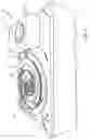
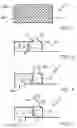
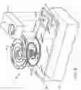
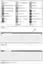
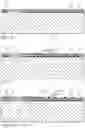
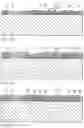
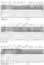
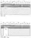
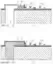
Sources:
- United States Patent and Trademark Office - verify current appl. status at the USPTO↗
Recent applications in this class:
- » 20250267236 2025-08-21
CONVERSION BETWEEN ASPECT RATIOS IN CAMERA - » 20250220127 2025-07-03
VIDEO PROCESSING METHOD, DEVICE, EQUIPMENT, AND STORAGE MEDIA - » 20250203036 2025-06-19
VIDEO IMAGE PROCESSING METHOD AND APPARATUS, AND DEVICE AND STORAGE MEDIUM - » 20250168293 2025-05-22
Bias Lighting Effect Generation for Videos - » 20250126220 2025-04-17
IMAGING APPARATUS CAPABLE OF SWITCHING DISPLAY METHODS - » 20250106349 2025-03-27
SYSTEMS AND METHODS FOR HORIZON LEVELING VIDEOS - » 20250106348 2025-03-27
EQUITABLE PRESENCE OF COMMUNICATION SESSION ATTENDEES - » 20250071232 2025-02-27
IMAGING APPARATUS AND IMAGING SYSTEM - » 20250039327 2025-01-30
DISPLAY METHOD - » 20250030812 2025-01-23
APPLICATION OF DOLLY ZOOM EFFECT TO VIDEOS
Recent applications for this Assignee:
- » 20120141040 2012-06-07
Method of compressing sequence of strokes - » 20120140280 2012-06-07
Electronically transmitted document delivery through interaction with printed document - » 20120118965 2012-05-17
Process for decoding coded data - » 20120111939 2012-05-10
Transaction recordal method - » 20120104089 2012-05-03
Electronic pen for interacting with substrate - » 20120083252 2012-04-05
Messaging via a coded business card and mobile telephone - » 20120062953 2012-03-15
Application for generating interactive document containing advertising material - » 20120057919 2012-03-08
Pen-shaped printing device - » 20120056003 2012-03-08
Substrate having coding pattern encoding Reed-Solomon symbols - » 20120044186 2012-02-23
Handheld display device having processor for rendering display output with real-time virtual transparency and form-filling option