Rotatable cutting tool for breaking hard material
US20050146199A1
2005-07-07
10/750,764
2004-01-05
Abstract:
A rotatable cutting tool for applications such as road resurfacing work includes a cutting bit insert and a tool body. The cutting bit insert includes an insert body and an inner tiered protrusion integrally formed from the insert body. The inner tiered protrusion has multiple tiers. The tool body has a tiered recess that corresponds to the inner tiered protrusion to hold the inner tiered protrusion. A combination of the inner tiered protrusion and the tiered recess provides a strong connection for the cutting bit insert and the tool body and keeps stress from concentrating at a single point.
Interested in similar patents?
Get notified when new applications in this technology area are published.
Classification:
B28D1/188 » CPC main
Working stone or stone-like materials, e.g. brick, concrete or glass , not provided for elsewhere; Machines, devices, tools therefor by milling, e.g. channelling by means of milling tools; Tools therefor, e.g. having exchangeable cutter bits with exchangeable cutter bits or cutter segments
E21C35/1831 » CPC further
Details of, or accessories for, machines for slitting or completely freeing the mineral from the seam not provided for in groups - , or; Mining picks; Holders therefor with inserts or layers of wear-resistant material Fixing methods or devices
Description
BACKGROUND OF THE INVENTION1. Field of the Invention
The present invention relates to a rotatable cutting tool, and more particularly to a cutting tool with a hard cutting bit insert mounted in a tool holder in a rotatable drum to break a hard surface into pieces.
2. Description of Related Art
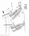
Road planers are used to remove pavement and prepare roads for resurfacing by grinding the pavement into pieces. With reference to FIGS. 4 to 6, a road planer (not shown) uses a rotatable drum (50) with multiple rotatable cutting tools (60) to break up and grind down a hard surface layer such as asphalt pavement. The rotatable drum (50) comprises multiple tool holders (61). Each of the tool holders (61) has a cylindrical hole (611) to hold a cutting tool (60). Each of the cutting tools (60) is held by the tool holder (61) and rotated by the rotatable drum (50) to break up and grind down the hard surface layer. The cylindrical hole (611) has an inside wall (not numbered).
The cutting tool (60) comprises an elongated tool body (62), a hard cutting bit insert (63) and a resilient retainer (64). The tool body (62) is normally cylindrical, is held in the cylindrical hole (611) by the resilient retainer (64) and has an inner end (not numbered), an outer end (not numbered) and an annular recess (not numbered). The resilient retainer (64) is mounted in the annular recess. The inner end of the tool body (62) is inserted into the cylindrical hole (611) with the resilient retainer (64) that expands against the inside wall of the cylindrical hole (611) so that the tool holder (61) retains or holds the cutting tool (60).
The outer end of the tool body (62) extends out of the hole (611). The cutting bit insert (63) is axially welded at the outer end of the tool body (62) and has a conical tip (not numbered) and a flat end (not numbered). The flat end is welded at the outer end of the tool body (62). The conical tip cuts a hard substance, such as asphalt, concrete or the like, on the road.
The tool body (62) is generally made of steel. The cutting bit insert (63) is generally made of a tungsten carbide alloy. To attach the cutting bit insert (63) to the tool body (62) by welding is not easy because they are made of different materials with different properties. Since the mechanical properties such as coefficients of expansion of the steel and the tungsten carbide alloy are different, heat generated by the operation of the cutting bit insert (63) breaking up the hard substances will effect the combination of the tool body (62) and the cutting bit insert (63). The tool body (62) and the cutting bit insert (63) expand at different rates as they heat up, which will stress the joint between the tool body (62) and the cutting bit insert (63) and cause the joint to fail.
The stress acting on the cutting bit insert (63) concentrates at the joint between the tool body (62) and the cutting bit insert (63). The heat and the stress will cause the cutting bit insert (63) to easily separate from the tool body (62) during the cutting operation.
With the cutting bit insert (63) broken off, the tool body (62) will directly impact the hard substances and be worn away by the hard surface. Since the tool body (62) is made of steel, the tool body (62) will be quickly worn away, and the tool holder (61) will be damaged or completely worn away. The damaged tool holder (61) cannot hold a new cutting tool (60) and must be replaced, which requires much more time than replacing a cutting tool (60). Therefore, keeping the cutting bit insert (63) from separating from the tool body (62) is necessary to prevent damage to the tool holder (61).
To overcome the shortcomings, the present invention provides an improved cutting tool with an enhanced joint between the tool body and the cutting bit insert to mitigate or obviate the aforementioned problems.
SUMMARY OF THE INVENTIONThe main objective of the invention is to provide a cutting tool with a tool body, a cutting bit insert and an enhanced joint between the tool body and the cutting bit insert to keep the cutting bit insert from separating easily from the tool body.
To achieve the main objective, a rotatable cutting tool for applications such as road resurfacing work includes a cutting bit insert and a tool body. The cutting bit insert includes an insert body and an inner tiered protrusion integrally formed from the insert body. The inner tiered protrusion has multiple tiers that are parallel to one another. The tool body has a tiered recess that corresponds to the inner tiered protrusion to hold entirely the inner tiered protrusion. A joint between the inner tiered protrusion and the tiered recess provides a strong connection and keeps stress from concentrating at a single point.
Other objectives, advantages and novel features of the invention will become more apparent from the following detailed description when taken in conjunction with the accompanying drawings.
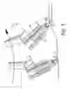
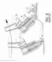
BRIEF DESCRIPTION OF THE DRAWINGSFIG. 1 is an operational side plan view in partial section of part of a rotatable drum with multiple tool holders and cutting tools in accordance with the present invention;
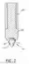
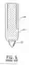
FIG. 2 is a side plan view in partial section of a cutting tool in FIG. 1;
FIG. 3 is an operational side plan view of the drum in FIG. 1;
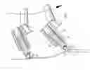
FIG. 4 is an operational side plan view of part of a rotatable drum with multiple tool holders and conventional cutting tools in accordance with the prior art;
FIG. 5 is a side plan view in partial section of a conventional cutting tool in FIG. 4; and
FIG. 6 is an operational side plan view of the rotatable drum in FIG. 4.
DETAILED DESCRIPTION OF PREFERRED EMBODIMENTWith reference to FIGS. 1 and 2, a cutting tool in accordance with the present invention is mounted in a conventional tool holder (61) on a rotatable drum (50) to break a hard surface into pieces. The cutting tool comprises a cutting bit insert (10), a tool body (20) and a resilient retainer (64). The cutting bit insert (10) can be made of tungsten carbide alloy and comprises an insert body (12) and an inner tiered protrusion (11). The insert body (12) has a conical tip (not numbered) and an inner flat end (not numbered). The inner tiered protrusion (11) is integrally formed on the inner flat end. The inner tiered protrusion (11) comprises a proximal tier (not numbered) and a distal tier (not numbered). The proximal tier protrudes perpendicular from the inner flat end of the insert body (12) and has a top (not numbered). The distal tier protrudes perpendicular from the top of the proximal tier.
The tool body (20) has an inner end (not numbered), an outer end (not numbered), a tiered recess (21) and an annular recess (not numbered). The inner end of the tool body (20) is held in the tool holder (61) by the resilient retainer (64) that is attached to the tool body (20) by being mounted in the annular recess to hold the tool body (20) in position. The tiered recess (21) is defined in the outer end of the tool body (20) and corresponds to the inner tiered protrusion (11) and the inner flat end of the insert body (12).
The inner tiered protrusion (11) and the inner flat end of the insert body (12) are welded in the tiered recess (21) of the tool body (20) and form a joint (not numbered). Therefore, the inner tiered protrusion (11) and the tiered recess (21) have a larger contact area than a conventional tool body and cutting bit insert. Therefore, stress applied to the insert body (12) will be directed into both vertical and horizontal directions to diminish the stress on any single edge. Therefore, the cutting bit insert (10) is much more difficult to separate from the tool body (20) during a cutting operation.
With reference to FIG. 3, the tiered design of the joint between the cutting bit inset (10) and the tool body (20) provides a robust and strong connection. An insert body (12) may fracture internally if it encounters a particularly hard substance, but the inner tiered end of the insert body (12) should still be retained on the tool body (20) to prevent the tool body (20) from wearing away.
Even though numerous characteristics and advantages of the present invention have been set forth in the foregoing description, together with details of the structure and function of the invention, the disclosure is illustrative only, and changes may be made in detail, especially in matters of shape, size, and arrangement of parts within the scope of the appended claims.
Claims
1. A rotatable cutting tool comprising:
a cutting bit insert comprising
an insert body having a conical tip and an inner flat end; and
an inner tiered protrusion integrally formed on the inner flat end;
a tool body having an outer end and a tiered recess defined in the outer end of the tool body to firmly hold the inner tiered protrusion and the inner flat end of the insert body; and
a resilient retainer attached to the tool body.
2. The rotatable cutting tool as claimed in claim 1, wherein the inner tiered protrusion comprises
a proximal tier with a top protruded perpendicularly from the inner flat end of the insert body; and
a distal tier protruded perpendicularly from the top of the proximal tier;
wherein the proximal tier, the distal tier and the inner flat end of the insert body are welded in the tiered recess of the tool body.
Images & Drawings included:
Sources:
- United States Patent and Trademark Office - verify current appl. status at the USPTO↗
Recent applications in this class:
- » 20240227239 2024-07-11
Retainer for a Rotating Bit - » 20240131747 2024-04-25
Retainer for a Rotating Bit - » 20230138956 2023-05-04
Milling tool - » 20220274290 2022-09-01
Milling systems and methods for a milling machine - » 20210283802 2021-09-16
Hammerless cutting bit retention system - » 20130328379 2013-12-12
Wear resistant cutting tool - » 20130300183 2013-11-14
Multi-Faced Cutting Tool - » 20130026811 2013-01-31
Tool insert - » 20130026810 2013-01-31
Cutting Tool Assembly with Protective Member - » 20120104833 2012-05-03
Wear insert and retainer