Sonic weld sunroof trim ring
US20050150930A1
2005-07-14
10/754,959
2004-01-08
✅ Patent granted
US 7,066,374 B2
2006-06-27
-
-
Jonathan Johnson
2024-04-03
Abstract:
A method of installing trim rings to headliner trims systems in motor vehicles comprising a trim ring, a headliner, and a sonic horn and stack. The sonic horn vibrates to bond/weld headliner to trim ring. Energy directors can be added to facilitate bonding/welding process. Fasteners can also be added for attachment to the vehicle body. This bonding/welding of the headliner to trim ring creates a smooth, molded look for the trim ring and does so without gapping to or sliding within the headliner.
Inventors:
- Michael C. Dykman 9 🇺🇸 Lake Orion, MI, United States
- John M. Tiesler 9 🇺🇸 Harrison Twp, MI, United States
- Jim Mestemaker 4 🇺🇸 Lambertville, MI, United States
- John M. Tiesler 24 🇺🇸 Harrison Township, MI, United States
- Scott D. Arnold 1 🇺🇸 Farrington Hill, MI, United States
- Scott D. Arnold 1 🇺🇸 Farmington Hills, MI, United States
Assignee:
- LEAR CORPORATION 2,208 🇺🇸 Southfield, MI, United States
Interested in similar patents?
Get notified when new applications in this technology area are published.
Classification:
B29C66/8322 » CPC main
General aspects of processes or apparatus for joining preformed parts; General aspects of machine operations or constructions and parts thereof characterised by the movement of the joining or pressing tools; Reciprocating joining or pressing tools Joining or pressing tools reciprocating along one axis
B29C65/08 » CPC further
Joining of preformed parts ; Apparatus therefor by heating, with or without pressure using ultrasonic vibrations
B29C66/112 » CPC further
General aspects of processes or apparatus for joining preformed parts; General aspects dealing with the joint area or with the area to be joined; Particular design of joint configurations particular design of the joint cross-sections; Joint cross-sections comprising a single joint-segment, i.e. one of the parts to be joined comprising a single joint-segment in the joint cross-section Single lapped joints
B29C66/1122 » CPC further
General aspects of processes or apparatus for joining preformed parts; General aspects dealing with the joint area or with the area to be joined; Particular design of joint configurations particular design of the joint cross-sections; Joint cross-sections comprising a single joint-segment, i.e. one of the parts to be joined comprising a single joint-segment in the joint cross-section; Single lapped joints Single lap to lap joints, i.e. overlap joints
B29C66/131 » CPC further
General aspects of processes or apparatus for joining preformed parts; General aspects dealing with the joint area or with the area to be joined; Particular design of joint configurations particular design of the joint cross-sections; Single flanged joints; Fin-type joints; Single hem joints; Edge joints; Interpenetrating fingered joints; Other specific particular designs of joint cross-sections not provided for in groups - Single flanged joints, i.e. one of the parts to be joined being rigid and flanged in the joint area
B29C66/3022 » CPC further
General aspects of processes or apparatus for joining preformed parts; General aspects dealing with the joint area or with the area to be joined; Particular design of joint configurations the area to be joined comprising melt initiators said melt initiators being integral with at least one of the parts to be joined
B29C66/474 » CPC further
General aspects of processes or apparatus for joining preformed parts; General aspects of joining substantially flat articles, e.g. plates, sheets or web-like materials; Making flat seams in tubular or hollow articles; Joining single elements to substantially flat surfaces; Joining single elements to sheets, plates or other substantially flat surfaces said single elements being substantially non-flat
B29C66/5344 » CPC further
General aspects of processes or apparatus for joining preformed parts; General aspects of joining tubular articles; General aspects of joining long products, i.e. bars or profiled elements; General aspects of joining single elements to tubular articles, hollow articles or bars; General aspects of joining several hollow-preforms to form hollow or tubular articles; Joining tubular articles, profiled elements or bars; Joining single elements to tubular articles, hollow articles or bars; Joining several hollow-preforms to form hollow or tubular articles; Joining single elements to tubular articles, hollow articles or bars; Joining single elements to open ends of tubular or hollow articles or to the ends of bars said single elements being substantially annular, i.e. of finite length, e.g. joining flanges to tube ends
B29C66/61 » CPC further
General aspects of processes or apparatus for joining preformed parts; General aspects of joining tubular articles; General aspects of joining long products, i.e. bars or profiled elements; General aspects of joining single elements to tubular articles, hollow articles or bars; General aspects of joining several hollow-preforms to form hollow or tubular articles Joining from or joining on the inside
B29C66/723 » CPC further
General aspects of processes or apparatus for joining preformed parts characterised by the composition, physical properties or the structure of the material of the parts to be joined; Joining with non-plastics material characterised by the structure of the material of the parts to be joined being multi-layered
B29C66/81427 » CPC further
General aspects of processes or apparatus for joining preformed parts; General aspects of machine operations or constructions and parts thereof; General aspects of the pressing elements, i.e. the elements applying pressure on the parts to be joined in the area to be joined, e.g. the welding jaws or clamps characterised by the design of the pressing elements, e.g. of the welding jaws or clamps characterised by the surface geometry of the part of the pressing elements, e.g. welding jaws or clamps, coming into contact with the parts to be joined comprising a single ridge, e.g. for making a weakening line; comprising a single tooth
B60R13/0231 » CPC further
Elements for body-finishing, identifying, or decorating; Arrangements or adaptations for advertising purposes; Trim mouldings Ledges; Wall liners for passenger compartments ; Roof liners; Roof or head liners specially adapted for roofs with openings
B29C66/21 » CPC further
General aspects of processes or apparatus for joining preformed parts; General aspects dealing with the joint area or with the area to be joined; Particular design of joint configurations particular design of the joint lines, e.g. of the weld lines said joint lines being formed by a single dot or dash or by several dots or dashes, i.e. spot joining or spot welding
B29L2007/002 » CPC further
Flat articles, e.g. films or sheets Panels; Plates; Sheets
B29L2031/3005 » CPC further
Other particular articles; Vehicles, e.g. ships or aircraft, or body parts thereof Body finishings
B29L2031/3011 » CPC further
Other particular articles; Vehicles, e.g. ships or aircraft, or body parts thereof; Body finishings Roof linings
B23K1/06 IPC
Soldering, e.g. brazing, or unsoldering making use of vibrations, e.g. supersonic vibrations
Description
FIELD OF INVENTIONThis invention relates to the field of sunroofs in motor vehicles. More specifically, it relates to an improved method of installing trim rings to headliner trim systems.
BACKGROUND OF INVENTIONSunroofs are very popular in motor vehicles. In their sunroofs, consumers want a smooth, molded look to make them more aesthetically pleasing. As a result, there has been a constant demand for better ways of utilizing a sunroof opening within a motor vehicle's headliner. Normally, there is some sort of secondary seal or molding that is used to make a sunroof opening more acceptable in appearance. See U.S. Pat. No. 4,231,609. In the '609 patent, the trim ring is complementary to the frame and is attached to the frame by fasteners so as to finish the bottom surface. Others use edging to create the desired appearance. One example is found in U.S. Pat. No. 6,161,895. In the '895 patent, the invention recognized the problem of having a headliner with an opening such as a sunroof and solved the problem of an unsatisfactory appearance by utilizing pleated edging around the sunroof opening. U.S. Pat. No. 5,108,147 utilizes grooves for fastening the headliner of a motor vehicle to the roof frame with a lifting or sliding roof structure. The '147 patent uses a lower groove to receive the edge of the flange and the upper groove receives the edge of the cut out portion. This method also produces the look that consumers want.
The problem with these typical ways of installing sunroofs is that there is not always a quality fit or alignment of the trim ring to the headliner. There can be gapping or sliding of the trim ring within the opening of the headliner. This invention relates to an improved method of installing sunroofs within a motor vehicle. It solves the problem of gapping and sliding and reduces the cost of tools. This invention also allows for assembly at the manufacturers plant and not on line at the original equipment manufacturer. This invention completely eliminates the need for edge wrapping to get a molded look for the sunroof opening by sonically welding the sunroof trim ring to the headliner.
SUMMARY OF INVENTIONThis invention relates to a method of installing trim rings to headliner trim systems comprising a trim ring, a headliner, and a sonic horn. This method allows for installation of trim rings, such as a sunroof trim ring, to achieve the smooth molded look consumers' desire, without any gapping or sliding.
This method of installing trim rings to headliner trim systems has the trim ring supported by a nest and the headliner is placed over the trim ring. The sonic horn vibrates to create the melt to bond/weld the trim ring to the headliner. The trim ring is bonded/welded at numerous points to the headliner.
The trim ring may further comprise energy directors to facilitate the bonding/welding process. These energy directors are small amounts of plastic that melt during the welding process to hold the trim ring and headliner together. Fasteners can also be added to the weld areas during to the bonding/welding process to provide for installation of the headliner to the vehicle body.
As a result of this invention, the trim ring is attached to the headliner trim system in a desired manner. There is no gapping or sliding within the opening of the headliner. Additionally, costs of tools are reduced and assembly can occur at the manufacturer's plant.
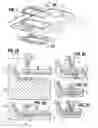
DETAILED DESCRIPTION OF THE DRAWINGSFIG. 1 depicts the trim ring within the headliner with nest.
FIG. 2A depicts a backside view of headliner with the trim ring, headliner, and sonic horn.
FIG. 2B depicts the headliner, trim ring, support nest and sonic horn beginning its bonding/welding cycle.
FIG. 2C depicts the sonic horn creating the melt.
FIG. 2D depicts the sonic horn bonding/welding the headliner to the trim ring.
FIG. 2E depicts the sonic horn finishing the bonding/welding process.
FIG. 3 is an overhead view of weld areas.
FIG. 4 is a typical section through the assembly.
DETAILED DESCRIPTION OF THE PREFERRED EMBODIMENTIn its preferred embodiment, this invention will relate to sunroof trim rings. Many motor vehicles have sunroofs and this invention solves the common problem of the trim ring 10 gapping or sliding from the headliner 12 and causing an improper fit. Improper fits can not only result in an undesirable appearance, but can also cause light/wind leakage through the sunroof. By bonding/welding the trim ring 10 to the headliner 12, the problems of gapping or sliding are eliminated.
In its preferred embodiment, this method of installing a trim ting 10 to a headliner 12 comprises a trim ring 10, a headliner 12, and a sonic horn 14. The sonic horn 14 comprises a tuned piece of material, such as aluminum or titanium. The sonic horn 14 works by utilizing a transducer connected to a power supply to produce a frequency. Preferably, this frequency will range between 15,000 Hz and 40,000 Hz. This frequency causes the sonic horn 14 to vibrate.
To create a bond/weld area 20, the trim ring 10 is supported by a nest 18. The headliner 12 is then placed over the trim ring 10. FIGS. 2A through 2E depicts the motion of the sonic weld 14 to bond/weld the headliner 12 to the trim ring 10. As the sonic horn vibrates, a melt is created that bonds/welds the headliner 12 to the trim ring 10. Energy directors 16 can be placed on the trim ring 10 to facilitate the welding process. These energy directors 16 comprise of plastic. As the sonic horn 14 vibrates, the energy directors 16 will melt and assist in bonding/welding the headliner 12 to the trim ring 10.
To assist in attachment of the headliner 12 to the vehicle body, fasteners 22, such as Velcro or Dual Lock can be welded during this welding process, as seen in FIG. 4. If a fastener 22 is used, it is located in a position above the weld area 20. The bonding/welding process takes place as described above and these fasteners 22 are used to attach the headliner 12 onto the sunroof bracket 24. If a fastener 22 is used, this size of such fastener 22 is preferably 50 mm×25 mm. This is so it best fits within the sunroof bracket 24 and trim ring 10 and will not overhang or causes any undesirable appearances. These fasteners 22 are simply meant to provide attachment of the headliner 12 to the sunroof bracket 24 and are not meant to be seen by consumers.
The bond/weld areas 20 are to be located at various locations around the trim ring 10 edge. The number of bond/weld areas 20 needed to properly bond/weld a trim ring 10 to a headliner 12 will vary depending on the size of the trim ring 10. The size of the actual bond/weld area 20 will vary as well, but these weld areas are preferably 50 mm×10 mm to ensure a strong weld and to create the smooth, molded look consumers' desire.
The above presents a description of the best mode contemplated for carrying out this invention. The claims should not be read as limited to the described order or elements unless stated to that effect. Therefore, all embodiments that come with the scope and spirit of the following claims and equivalents thereto are claimed as the invention.
Claims
1. A method of installing a trim ring to a headliner of a motor vehicle comprising the steps of:
stacking a sonic horn with the headliner and the trim ring; and
vibrating the sonic horn such that the trim ring and the headliner bond and weld together in at least one weld area.
2. The method of installing a trim ring to a headliner in claim 1, further comprising the step of providing a nest and wherein said step of stacking the sonic horn with headliner and the trim ring occurs on the nest such that the trim ring, the headliner and the sonic horn are supported by the nest.
3. The method of installing a trim ring to a headliner in claim 1, wherein said step of vibrating the sonic horn such that the trim ring and the headliner bond and weld together in at least one weld area creates numerous weld areas around perimeter of said trim ring.
4. The method of installing a trim ring to a headliner in claim 1, wherein said step of stacking the trim ring, the headliner, and a sonic horn further comprises including at least one energy director between the trim ring and the headliner.
5. The method of installing a trim i ring to a headliner as in claim 4, wherein said energy directors comprise of plastic.
6. The method of installing a trim ring to a headliner as in claim 1, further comprising the step of fastening the headliner to a sunroof bracket with fasteners.
7. The method of installing a trim ring to a headliner as set forth in claim 1 wherein said step of stacking a sonic horn with the headliner and the trim ring includes stacking a band-shaped sonic horn with the headliner and the trim ring.
8. The method of installing a trim ring to a headliner as set forth in claim 1 wherein said step of stacking the sonic horn with the headliner and the trim ring includes positioning the headliner between the sonic ring and the trim ring.
Images & Drawings included:


Sources:
- United States Patent and Trademark Office - verify current appl. status at the USPTO↗
Recent applications in this class:
- » 20250033297 2025-01-30
VIBRATION WELDING DEVICE AND VIBRATION WELDING METHOD - » 20230081335 2023-03-16
Vibration welding device and vibration welding method - » 20200156328 2020-05-21
Ultrasonic vibration welding apparatus - » 20180056600 2018-03-01
Assembling device - » 20100221995 2010-09-02
Ventilation member and method of manufacturing the same - » 20070228106 2007-10-04
PROCESS AND DEVICE FOR FORM LOCKED JOINING OF TWO COMPONENTS - » 20070204954 2007-09-06
Process and device for form locked joining of two components - » 20070133220 2007-06-14
Vehicle lighting device - » 20060137818 2006-06-29
Laminating apparatus and method - » 20050272142 2005-12-08
Fluid vessel
Recent applications for this Assignee:
- » 20250279621 2025-09-04
ELECTRICAL ASSEMBLY - » 20250276622 2025-09-04
SEAT ASSEMBLY - » 20250219384 2025-07-03
AUXILIARY ELECTRIC SPLICE - » 20250219333 2025-07-03
High Voltage Shielded Electrical Connector - » 20250219330 2025-07-03
HIGH VOLTAGE SHIELDED ELECTRICAL CONNECTOR - » 20250219321 2025-07-03
HIGH VOLTAGE ELECTRICAL CONNECTOR - » 20250202457 2025-06-19
APPARATUS FOR PROVIDING PARALLEL FILTERING - » 20250196740 2025-06-19
SEAT ASSEMBLY - » 20250194036 2025-06-12
ELECTRICAL ASSEMBLY - » 20250192500 2025-06-12
TRACK ASSEMBLY