Composite beam
US20050166530A1
2005-08-04
10/761,649
2004-01-14
Abstract:
A structural beam has a thin metal web with a plurality of holes located along its top and bottom edges. One or more rectangular flange pieces are located on each side of the web overlying its top margin and one or more rectangular flange pieces are located on each side of the web overlying its bottom margin. The flange pieces contain holes which are aligned with the holes in the web piece and fasteners extend through the aligned holes to fasten the flange pieces to the web.
Interested in similar patents?
Get notified when new applications in this technology area are published.
Classification:
E04C3/292 » CPC main
Structural elongated elements designed for load-supporting; Joists; Girders, trusses, or trusslike structures, e.g. prefabricated; Lintels; Transoms; Braces built-up from parts of different material, i.e. composite structures the materials being wood and metal
Description
BACKGROUND AND SUMMARY OF THE INVENTIONThis invention relates to a structural beam and, in particular, to a structural beam that is a composite of metal and wood elements.
Light commercial and industrial structures, such as warehouses, are often constructed as wood frame structures in order to reduce the cost. Several types of large wood beams (24 inches to 4 feet high) are used for this purpose. The least costly of these beams are gluelam beams. Gluelam beams are well known and widely used but are dimensionally unstable. The larger the beam, the more this dimensional instability becomes a problem. At the other end of the spectrum, parallel strand lumber beams are very dimensionally stable, but their cost approaches that of steel beams. While the overall cost of constructing a building using parallel strand lumber beams is less than using steel beams, other advantages of steel often outweigh this relatively minor cost differential and large parallel strand lumber beams have not been widely used in light commercial and industrial buildings.
The subject invention provides a composite wood/steel beam having a cost which is compatible with gluelam beams and yet has the dimensional stability of parallel strand beams, or even steel beams. This is accomplished by providing a planer steel web with wood top and bottom flange pieces, which are separate from the web and from one another. The top and bottom flange pieces are attached to the top and bottom edges of the web respectively, with one top and bottom flange piece being on each side of the web.
The foregoing and other objectives, features, and advantages of the invention will be more readily understood upon consideration of the following detailed description of the invention, taken in conjunction with the accompanying drawings.
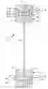
BRIEF DESCRIPTION OF THE SEVERAL VIEWS OF THE DRAWINGSFIG. 1 is a foreshortened perspective view showing a beam embodying the subject invention.
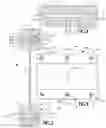
FIG. 2 is a cross-sectional view, at an enlarged scale, taken along the line 2-2 of FIG. 1.
FIG. 3 is a detail view, at an enlarged scale, of an alternative embodiment of the invention.
DETAILED DESCRIPTION OF THE PREFERRED EMBODIMENTReferring now to FIGS. 1 and 2 of the drawings, a beam 10 includes a planer web 12, the web 12 is preferably made from an elongate thin piece of a relatively high-strength metal, such as steel, however it can be any material that will withstand the load that will be transmitted to the resulting beam. The web has a length which is substantially equal to the desired length of the beam and a height which is substantially equal to the desired height of the beam. The thickness of the web depends on the size of the beam and the load it is intended to carry, but it is relatively thin.
Located respectively at the top and bottom edges of the web are flanges 14a and 15b. The flanges are separate from the web and separate flange pieces 16 are located on each side of the web. A plurality of holes 18 extend through the web at spaced apart intervals along its upper and lower margins. A plurality of similar holes 20 extend through the flange pieces 16, and the holes 20 are aligned with the holes 18 when the flange pieces overlie the top and bottom margins of the web. Counterbores 22 are aligned with the holes 20 at the outside of each flange piece. Fasteners 24 extend through the holes 18 and 20 to secure the flange pieces to the web. In the embodiment illustrated, the fasteners 24 are bolts 26 which have heads 28 that fit within the counterbores at one side of the beam, and nuts 30 which fit within the counterbores at the other side of the beam.
The flange pieces preferably are made from a material that nails can be driven into, in order that the resulting beam can easily be utilized in conjunction with other wood elements. The flange pieces ideally are parallel strand lumber in order to also provide a high level of dimensional stability. High dimensional stability is particularly important where the flange pieces are separate from the web and attached to the web with fasteners because shrinkage of the flange pieces would cause their connection to the web to become loose. Alternatively, the flange pieces could be other wood products that have a reasonable level of dimensional stability or even simply be dimension lumber. The size of the flange pieces depends upon the size of the beam and the intended load. A representative beam, which would be used for roof or floor joists in a building, would have a web thickness of ⅛ inch to ½ inch, a web height of 1-4 feet and the flange pieces would be 3½ inches wide. If it is necessary to have flanges which are larger than are available in one piece of lumber, multiple flange pieces 16 can be placed on each side of the web, FIG. 3.
The web 12 preferably will have central openings 32 located in it which will allow wire, cables, pipes and the like to be easily passed through the beam. The size, shape, location and number of openings will depend on the intended use of the beam, and a simple circular opening is shown in the drawing for illustration purposes. The openings 32 and the holes 18 can be formed in the web in a single operation by stamping.
Due to its use of common, readily available materials, the beam of the subject invention is quickly and easily fabricated without requiring costly tooling or equipment. The beam of the subject invention provides the nailability and dimensional stability of a parallel strand lumber beam at a far lower cost than a beam made entirely of this material, and, in addition, provides performance which is comparable to metal beams.
The terms and expressions which have been employed in the foregoing specification are used therein as terms of description and not of limitation, and there is no intention, in the use of such terms and expressions, of excluding equivalents of the features shown and described or portions thereof, it being recognized that the scope of the invention is defined and limited only by the claims which follow.
Claims
1. A beam for supporting a structural load comprising:
(a) A planer web having a top edge, a bottom edge, a length and a thickness;
(b) said web defining a plurality of holes proximate its top edge and a plurality of holes proximate its bottom edge;
(c) at least two rectangular top flange pieces which are separated from said web, one of said top flange pieces being located on each side of said web adjacent said top edge;
(d) said top flange pieces defining a plurality of holes which are aligned with the holes in said web proximate said top edge;
(e) a plurality of fasteners which extend through the holes in said top flange pieces and the holes in said web proximate said top edge and secure said top flange pieces to said web;
(f) at least two rectangular bottom flange pieces which are separated from said web, one of said top flange pieces being located on each side of said web adjacent said bottom edge;
(g) said bottom flange pieces defining a plurality of holes which are aligned with the holes in said web proximate said top edge; and
(h) a plurality of fasteners which extend through the holes in said bottom flange pieces and the holes in said web proximately said bottom edge and secure said bottom flange pieces to said web.
2. The beam of claim 1 wherein said web is a thin metal sheet.
3. The beam of claim 2 wherein said web has a thickness of between ⅛ inch and ½ inch.
4. The beam of claim 3 wherein said web has a height between 1 foot and 4 feet.
5. The beam of claim 1 wherein said top and bottom flange pieces are parallel strand lumber.
6. The beam of claim 1 wherein said top and bottom flange pieces are dimension lumber.
7. The beam of claim 1 wherein there is one of said top and bottom flange pieces on each side of said web.
8. The beam of claim 1 wherein there are more than one of said top and bottom flange pieces on each side of said web.
9. The beam of claim 1 wherein the holes in said top and bottom flange pieces contain counterbores.
10. The beam of claim 1 wherein said fasteners comprise bolts having heads which fit in the counterbores on the flange pieces on one side of said web and nuts which fit in the counterbores on the flange pieces on the other side of said web.
11. The beam of claim 1 where at least one hole is defined in said web between said top and bottom flange pieces.
Images & Drawings included:
Sources:
- United States Patent and Trademark Office - verify current appl. status at the USPTO↗
Similar patent applications:
- » 20060147704
Aircraft structure including composite beam and composite panel with metal foil therebetween - » 20210296079
Particle beam apparatus and composite beam apparatus - » 20190176889
Cross car beam assembly with composite beam structure and reinforcement - » 20050231808
Apparatus and method for combining multiple electromagnetic beams into a composite beam - » 20230037589
Steel plate built-up beam for steel-concrete composite beam - » 20110247297
Formed steel beam for steel-concrete composite beam and slab - » 20070242327
Scanned beam source and systems using a scanned beam source for producing a wavelength-compensated composite beam of light - » 20060197244
Mold fixture to densify composite beam key using resin transfer molding - » 20050248424
Composite beam microelectromechanical system switch - » 20070056246
Composite beam with corrugated web
Recent applications in this class:
- » 20240263450 2024-08-08
Composite Floor Beam - » 20230047686 2023-02-16
WOOD-STEEL COMPOSITE STRUCTURAL BEAM - » 20220154468 2022-05-19
Structural truss module with fastener web and manufacturing method therefor - » 20220145631 2022-05-12
Building stud, wall structure comprising such a building stud and a method for forming a wall structure - » 20180202162 2018-07-19
Composite I-truss - » 20170058526 2017-03-02
Structural truss module with fastener web and manufacturing method therefor - » 20150225956 2015-08-13
Truss and column structures incorporating natural round timbers and natural branched round timbers - » 20150135638 2015-05-21
Composite I-beam member - » 20130239512 2013-09-19
Steel and wood composite structure with metal jacket wood studs and rods - » 20130160398 2013-06-27
Composite I-beam member